Article

Power Stabilization based on Switching Control of Segmented Transmitting Coils for Multi Loads in Static-Dynamic Hybrid Wireless Charging System at Traffic Lights

1
Department of Electrical Engineering, Southeast University, Nanjing 210096, China
2
Key Laboratory of smart grid technology and equipment in Jiangsu province, Zhenjiang 212000, China
*
Author to whom correspondence should be addressed.
Energies 2019, 12(4), 607; https://doi.org/10.3390/en12040607
Submission received: 28 January 2019 / Revised: 10 February 2019 / Accepted: 12 February 2019 / Published: 14 February 2019

Abstract

:
In order to promote the driving range of the electric vehicles (EVs), decrease the demand for large capacity battery and create more charging opportunities for the EVs, the static-dynamic hybrid wireless charging system is presented to utilize waiting time of traffic lights at intersections to replenish electricity in this paper. Firstly, the topology and principle of the proposed static-dynamic hybrid wireless charging system with short-segmented coils at traffic lights are introduced. Secondly, the general circuit model of the static-dynamic hybrid wireless charging system with multi-coupling between the primary and secondary sides is developed. The design method of the compensation circuit in primary side based on the number and the positions of the energized primary coils is investigated. After analyzing the characteristics of the system varying with the position of the single load, the control conceptions of the energizing mode alternating in primary side and the combination of the primary compensation capacitors are put forward. Then the power stabilization control strategy of the static-dynamic hybrid wireless charging system with multi short-segmented coils and multi loads is proposed. Finally, the theoretical analyses are verified with the experiments.

1. Introduction

In recent years, the energy crisis and environmental problems have accelerated the development of electric vehicles (EVs). However, compared with fuel vehicles, EVs are still faced with problems such as large size and low energy density of energy storage equipment, frequent charging and insufficient driving range [1]. The static wireless charging technology for EVs is helpful to solve the issues of wired charging, such as frequent plug-in, contact wear and tear, electric shock risk and lack of user experience [2].
In the field of static wireless charging technology, the research points mainly includes the design of the high-frequent inverter [3,4], the design of the wireless energy transceivers [5], the design of the compensation circuits [6,7], the optimization of the receiving power and efficiency [8,9], the foreign object detection [10,11] and the issue of the electromagnetic field [12]. The multi-phase resonant inverter is proposed to realize the high output power for wireless charging system of EVs in Reference [3] and [4]. The Pareto optimization of inductive power transfer coil with respect to efficiency and area-related power density for EVs is introduced in Reference [5]. In Reference [6] and [7], the LCL (inductance-capacitance-inductance) and LCC (inductance-capacitance-capacitance) compensation topologies are proposed respectively for wireless charging systems. The tracking method of the maximum efficiency is studied for the wireless charging system in Reference [8]. The living object detection system based on comb pattern capacitive sensor is proposed for wireless EV chargers in Reference [10]. The resonant reactive shield for a wireless charging system of EVs is designed to decrease the electromagnetic radiation level in Reference [12].
To solve the issues of frequent charging and short driving range of EVs further, the dynamic wireless charging (online charging) technology is put forward. According to the different structures of the energy transmitting side, the dynamic wireless charging systems can be divided into two categories including the systems with long rail structure and the systems with short-segmented coil structure [13]. In the dynamic wireless charging system for EVs with short-segmented coils, the segmented transmitting coils need to be turned on or off by the switching control equipment according to the positions of EVs. Hence, compared with the systems with long rail structure, only several relevant segmented coils rather than the whole primary coils need to be energized in the systems with short-segmented coils. The loss in primary side is less and the issue of electromagnetic field is relatively easy to solve. However, the systems with short-segmented coils depend on the positioning technology [14] and the switching control technology to realize the coil excitation orderly. Hence, the research on the dynamic wireless charging systems with short-segmented coils focuses on the positioning method, the design of the magnetic coupling units [15,16] and the misalignment issue [17].
The static wireless charging technology for EVs is gradually transitioning from laboratory environment to practicality and commercialization [18,19]. But the dynamic wireless charging technology for EVs has not been widely used due to its cost and the road construction problems. After giving a comprehensive consideration to the development of static wireless charging technology and the compatibility with dynamic wireless charging in the future, the static-dynamic hybrid wireless charging system based on short-segmented coils is presented to utilize waiting time of traffic lights at intersections to replenish electricity in this paper. The system allows random dynamic access and random static parking of multiple EVs. On the one hand, with the random variation of the number and locations of EVs, the number and connection of the segmented coils in primary side is changed which will cause the detuning of the primary side and the receiving power drop further. On the other hand, during the moving process of the loads, the coupling strength varies rapidly when the segmented coils are energized one by one, which also causes the fluctuation of the receiving power. Connection topologies of the segmented coils and the compensation capacitors in primary side can be adaptively changed according to the number and locations of EVs to solve the power fluctuation problem in the dynamic process of loads. On the basis of the structure of the static-dynamic hybrid wireless charging system, this paper focuses on the control of the energizing mode alternating in primary side and the combination of the primary compensation capacitors according to the number and positions of the loads.
In this paper, a static-dynamic hybrid wireless charging system with segmented coils for multiple EVs at a crossing with traffic lights is proposed. Especially, to deal with the random variation of the number and the positions of the EVs, the power stabilization control strategy of the static-dynamic hybrid wireless charging system with multi short-segmented coils and multi loads is put forward based on the switching control of the segmented coils and the multiple compensation circuit in primary side. In Section 2, the topology and principle of the proposed static-dynamic hybrid wireless charging system with short-segmented coils for multiple EVs are introduced. In Section 3, the general circuit model of the system with multi-coupling between the primary and secondary sides is developed. The design method of the compensation circuit in primary side based on the number and the positions of the energized primary coils is investigated. In Section 4, the characteristics of the system varying with the position of the single load are analyzed. In Section 5, the control conceptions of the energizing mode alternating in primary side and the combination of the primary compensation capacitors are put forward. The power stabilization control strategy of the static-dynamic hybrid wireless charging system with multi short-segmented coils and multi loads is proposed. The experiments are carried out to verify the theoretical analysis in Section 6 and the conclusions are provided in Section 7.

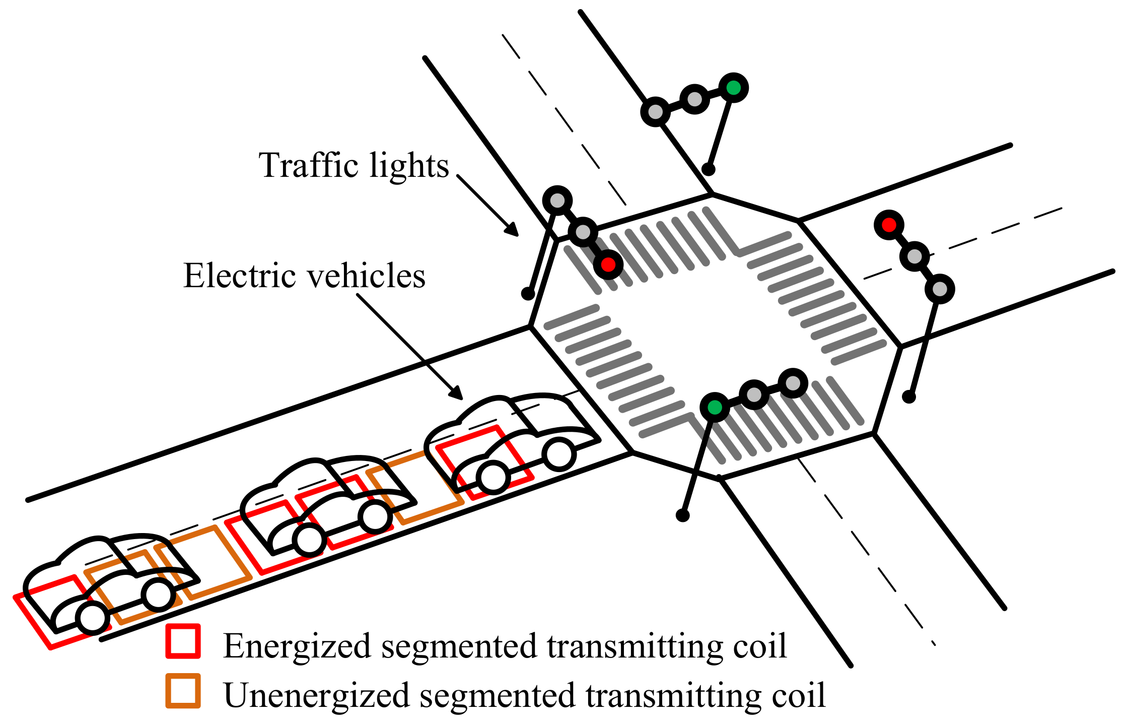
2. System Description
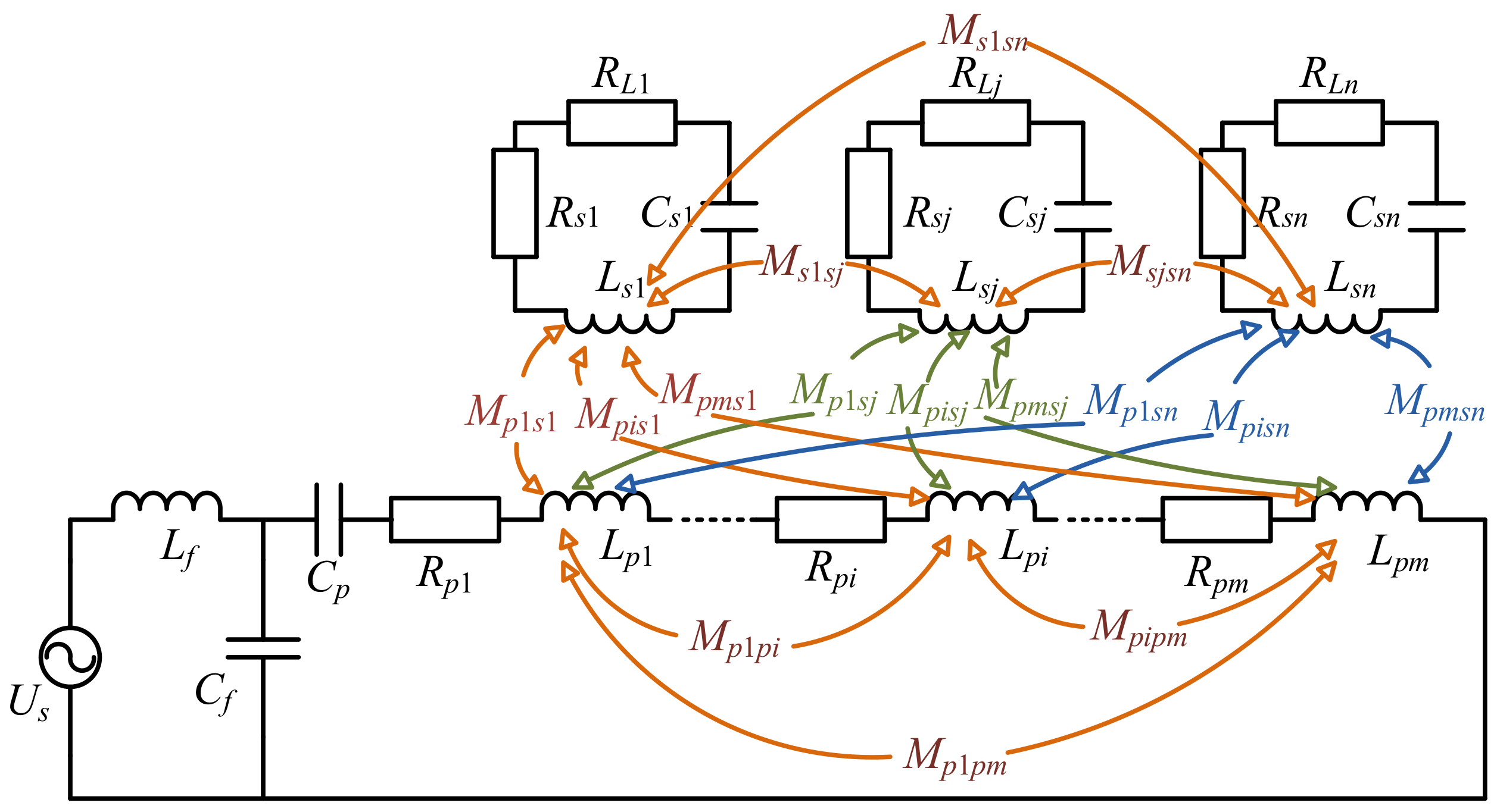
The schematic diagram of the proposed static-dynamic hybrid wireless charging system with segmented coils for multiple EVs at a crossing with traffic lights is shown in Figure 1. The proposed system is built at a crossing with traffic lights to charging wirelessly for the EVs which wait for the red lights. The short-segmented coils in primary side are installed under the road. The receiving coil is installed under the chassis of electric vehicle. Energy is transferred from the road to the EVs wirelessly through the magnetic coupling between the transmitting coils and the receiving coils. Additionally, when the traffic light is green, the proposed system is also one part of the dynamic wireless charging system for the running EVs on road. During the process that the system operates as the dynamic wireless charging system while the traffic light is green, most research of the dynamic wireless charging system contains only one load according to the system structure and the safe driving distance, such as [20] and [21]. While the traffic light is red, the EVs in the proposed system are parking or moving with a very low speed. Moreover, the proposed system also can contain multiple loads. Hence, this paper focuses on the switching control of the segmented coils in primary side and the power stabilization issue of multiple loads in the proposed static-dynamic hybrid wireless charging system.
The structure diagram of the proposed static-dynamic hybrid wireless charging system with segmented coils for multiple EVs is shown in Figure 2. The primary side includes the high-frequency inverter, the fix part of primary compensation circuit, the variable part of primary compensation circuit, the short-segmented primary coils and the switching control devices. The secondary side contains the receiving coil, the secondary compensation circuit, the rectifier and load. According to the static or dynamic positions of EVs, the segmented primary coils are turned on or off by the switching control devices. The variable part of primary compensation circuit consists of the multiple fixed capacitors and the switching control devices. The multiple compensation capacitors are selected by the switching control devices according to the number and the positions of the energized segmented primary coils. In actual situations, the length of secondary coil under the electric vehicle is no more than a half of the length of the EV. Hence, the secondary coils of the multiple EVs are far away from others. As shown in Figure 2, the segmented primary coils are controlled independently according to the positions of the secondary coils even multiple EVs in the system. After turning on the segmented primary coils related to the near secondary coils and selecting the corresponding primary compensation capacitor according to the control strategy, the energy is transferred wirelessly from the road side to the EVs through the magnetic coupling between the primary and secondary coils.

3. System Modeling

In the proposed static-dynamic hybrid wireless charging system for multiple EVs at a crossing, the accessed EVs are characterized by the random number and random positions. In order to investigate the system circuit topology, the compensation topology and the system characteristics influenced by the uncertain factors mentioned before, the general circuit model of the wireless power transfer system with multiple transmitters and multiple receivers is developed as shown in Figure 3. Us represents the output voltage of the high-frequency inverter. f is the operation frequency of the system. The angular frequency is denoted as ω = 2 π f . The primary compensation circuit consists of the inductance Lf, the capacitors Cf and Cp. Lf and Cf are the fixed part of the primary compensation circuit. Cp, including the multiple fixed compensation capacitors and the switching control devices, is the variable part of the primary compensation circuit. In primary side, the multiple segmented transmitting coils are connected in series. m is the total number of the transmitting coils. Rpi and Lpi represent the resistance and the inductance of the ith ( i = 1 , 2 , , m ) transmitting coil. The whole system also contains multiple receivers. n represents the total number of the receivers. Rsj and Lsj denote the resistance and inductance of the jth ( j = 1 , 2 , , n ) receiving coil. Csj is the secondary compensation capacitor of the jth receiving coil. RLj is the jth load. Mphpi is the mutual inductance between the hth energized transmitting coil and the ith energized transmitting coil, where i = 1 , 2 , , m and h = 1 , 2 , , i 1 . Msjsk is the mutual inductance between the jth receiving coil and the kth receiving coil, where j = 1 , 2 , , n and k = 1 , 2 , , j 1 . Mpisj is the mutual inductance between the ith energized transmitting coil and the jth receiving coil.
The output current of the high-frequency inverter is represented as If. the current through the transmitting coils are denoted as Ip. The current through the jth receiving circuit is Isj. According to the circuit theory of the mutual inductance, the circuit equations are established as Equation (1),
[ Z f Z C f 0 0 0 Z C f Z p Z M p s 1 Z M p s j Z M p s n 0 Z M p s 1 Z s 1 Z M s 1 s j Z M s 1 s n 0 Z M p s j Z M s 1 s j Z s j Z M s j s n 0 Z M p s n Z M s 1 s n Z M s j s n Z s n ] · [ I f I p I s 1 I s j I s n ] = [ U s 0 0 0 0 ]
where Z f = j ω L f + 1 j ω C f , Z C f = 1 j ω C f , the equivalent total inductance in primary side L p s u m = i = 1 m L p i + 2 i = 1 m 1 h = i + 1 m M p h p i ( m 2 ) , the equivalent total resistance in primary side R p s u m = i = 1 m R p i , Z p = 1 j ω C f + 1 j ω C p + j ω L p s u m + R p s u m . The equivalent mutual inductance between the jth receiving coil and the whole primary side is M p s j = i = 1 m M p i s j . Z M p s j = j ω M p s j , Z s j = j ω L s j + 1 j ω C s j + R s j + R L j , Z M s j s k = j ω M s j s k .
Considering the actual situation, the receiving coils under each electric vehicle are far away from others. Hence, the mutual inductance between the receiving coils M s j s k = 0 . In each receiving circuit, the compensation circuit should satisfy that
C s j = 1 ω 2 L s j
The components of the LCC compensation circuit in primary side should satisfy that
j ω L f + 1 j ω C f = 0
1 j ω C p + j ω ( i = 1 m L p i + 2 i = 1 m h = 1 i 1 M p h p i L f ) = 0
According to the analysis above, Equation (1) can be written as
[ 0 j ω L f 0 0 0 j ω L f R p s u m j ω M p s 1 j ω M p s j j ω M p s n 0 j ω M p s 1 R s 1 + R L 1 0 0 0 j ω M p s j 0 R s j + R L j 0 0 j ω M p s n 0 0 R s n + R L n ] · [ I f I p I s 1 I s j I s n ] = [ U s 0 0 0 0 ]
The current through the primary coils is derived as
I p = U s j ω L f
The current through the jth receiving coil is represented as
I s j = j ω M p s j I p ( R s j + R L j ) = U s M p s j L f ( R s j + R L j )
The receiving power of the jth load is denoted as
P s j = I s j 2 R L j = U s 2 ( i = 1 m M p i s j ) 2 R L j L f 2 ( R s j + R L j ) 2
The system efficiency is
η = j = 1 n | I s j | 2 R L j | I p | 2 i = 1 m R p i + j = 1 n | I s j | 2 ( R s j + R L j ) = j = 1 n ω 2 ( i = 1 m M p i s j ) 2 ( R s j + R L j ) 2 R L j i = 1 m R p i + j = 1 n ω 2 ( i = 1 m M p i s j ) 2 R s j + R L j
The general circuit model of the wireless power transfer system with complex coupling between the multiple transmitting coils and the receiving coils is developed. The relationship between the variable part of the primary compensation circuit Cp and the multiple transmitting coils is investigated. The analysis above lays the foundation for the design method of the primary compensation circuit based on the number and positions of the loads. According to the system circuit model, the expressions of the receiving power of each load about the mutual inductances are derived. The system efficiency varying with the number of loads and the mutual inductances is also deduced. The relationship between the system characteristics and the positions of multiple loads will be studied in detail in the following part.

4. System Characteristics Analysis

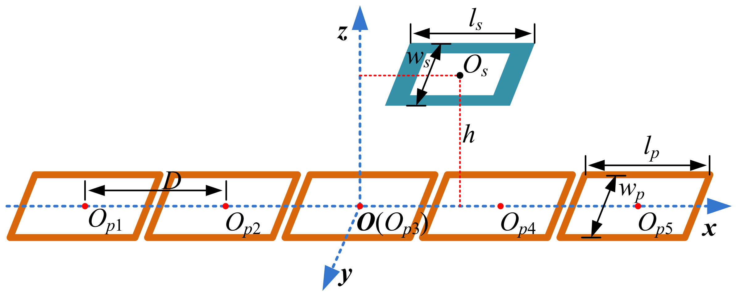
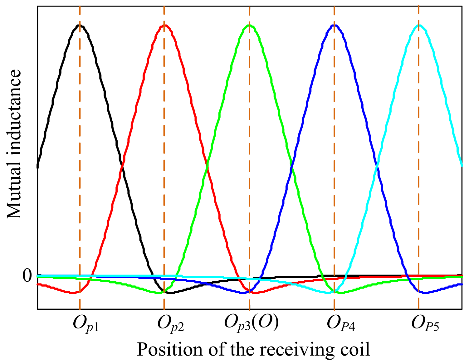
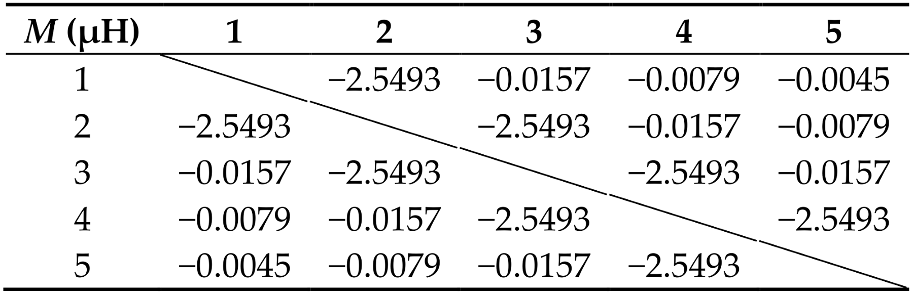
4.1. The Variation Characteristics of Mutual Inductance between the Primary and Secondary Sides

The schematic diagram of multiple transmitting coil and single receiving coil is shown in Figure 4. In this paper, the multiple transmitting coils are identical rectangular space spiral coils. The multiple receiving coils are identical rectangular planar spiral coil. The parameters of coils are listed in Table 1. lp and wp are the length and width of the transmitting coils respectively. ls and ws are the outer length and outer width of the receiving coils respectively. N1 and N2 are the turns of the transmitting coils and the receiving coils respectively. D is the distance between the centers of the adjacent transmitting coils. h is the vertical height between transmitting and receiving coils. This paper focuses on the characteristics caused by the movement through the road direction. The issue of lateral misalignment is ignored. In this proposed system, the primary side includes five segmented transmitting coils. Op1 to Op5 represent the centers of the transmitting coils respectively. The coordinates are expressed as Op1 (−2D, 0, 0), Op2 (−D, 0, 0), Op3 (0, 0, 0), Op4 (D, 0, 0) and Op5 (2D, 0, 0). Os is the center of the receiving coil. The coordinate is Os (xs, 0, h).
The mutual inductance between the transmitting coils and the receiving coil at different position is calculated according to the Neumann formula [22]. The mutual inductance between the loop l p i of the ith transmitting coil and the loop l s j of the jth receiving coil is derived as
M p i s j = μ 0 4 π l p i l s j d l p i · d l s j R i j
where μ 0 is the vacuum permeability. R i j is used to denote the distance between the transmitting current infinitesimal and the receiving current infinitesimal.
As shown in Figure 5, the characteristics of the mutual inductances between the receiving coil and the transmitting coils varying with the position of the single receiving coil are obtained respectively according to Equation (10).
The mutual inductance between the single transmitting coil and the single receiving coil fluctuates significantly varying with the position of the receiving coil. According to Figure 5, when the single energizing mode of transmitting coils is applied, the optimal position of the switching control is the middle position of the two adjacent transmitting coils. However, the mutual inductance still fluctuates in dynamic wireless charging system with single energizing mode while the receiving coil moves. Based on Equation (8), the fluctuation of the mutual inductance will influence the stabilization of the receiving power. In addition, when the receiving coil is aligned with a transmitting coil, the mutual inductance between the receiving coil and the aligned transmitting coil is far greater than the mutual inductance between the receiving coil and other transmitting coils. When the receiving coil is at the middle position between two adjacent transmitting coils, the mutual inductance between the receiving coil and those two adjacent transmitting coils is higher that the mutual inductance between the receiving coil and other transmitting coils but lower than the maximum value of the mutual inductance at the aligned position.

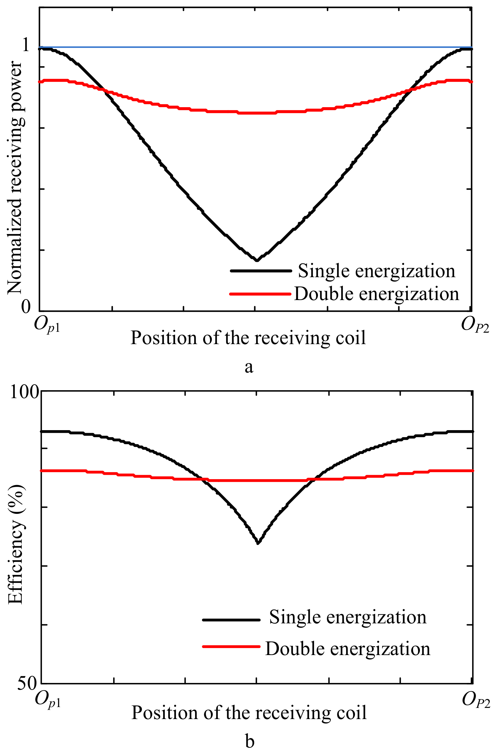
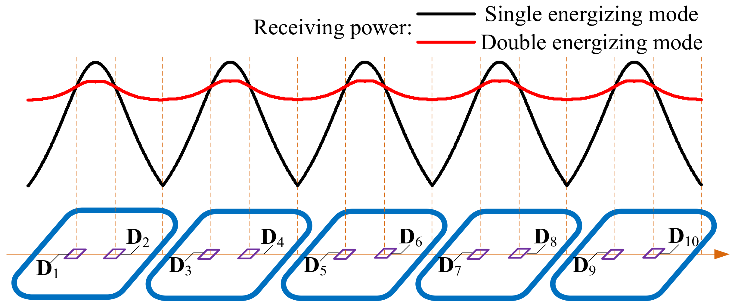
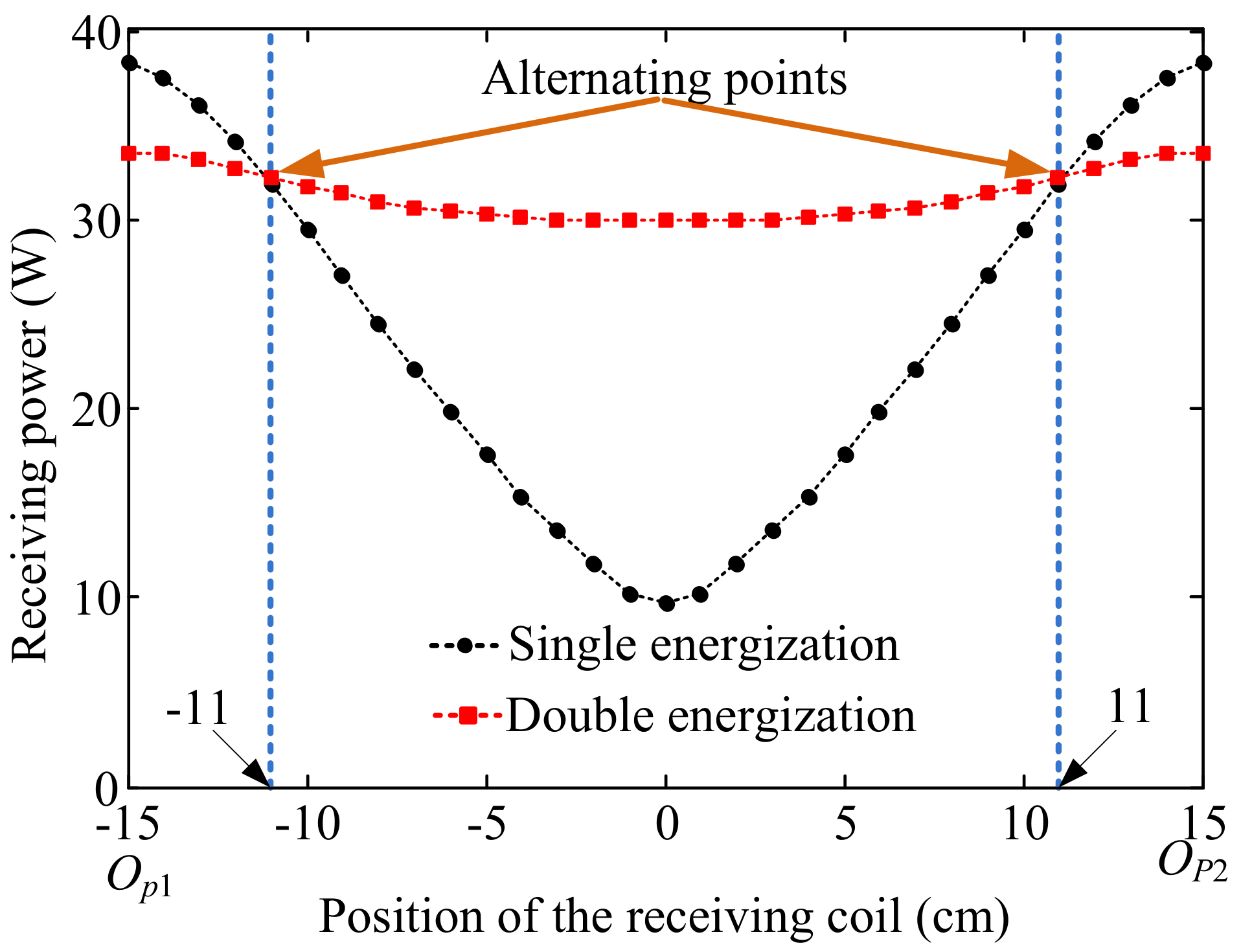
4.2. The Comparative Analysis of the Energizing Mode of the Transmitting Coils for a Single Load

According to the analysis of mutual inductance above, during the movement process of a single load, the receiving coil is only strongly coupled with one or two transmitting coils. The magnetic coupling between the receiving coil and the other transmitting coils are weak and in opposite direction. For a single load, the region between Op1 and Op2 is selected as an example to investigate the comparative characteristics of the single energizing mode and the double energizing mode of the transmitting coils.
In the system of the single energizing mode, the equivalent total mutual inductance between the primary and secondary sides is represented as
M s i n g l e = { M p 1 s a ,   x s [ O p 1 , O p 1 p 2 ) M p 2 s a ,   x s [ O p 1 p 2 , O p 2 )
In the system of the double energizing mode, the equivalent total mutual inductance between the primary and secondary sides is represented as
M d o u b l e = M p 1 s a + M p 2 s a ,   x s [ O p 1 , O p 2 )
According to Equation (10), the comparative characteristics of the equivalent total mutual inductance between the primary and secondary sides varying with the movement of the receiving coil in one switching control cycle ( x s [ O p 1 ,   O p 2 ) ) is obtained as shown in Figure 6. When the receiving coil is at the aligned position of one transmitting coil, the equivalent mutual inductance of the single energizing mode is higher slightly than that of the double energizing mode. The slightly lower mutual inductance is caused by the opposite coupling between the receiving coil and anther transmitting coil. Obviously, when the receiving coil is at the middle position of two transmitting coils, the equivalent mutual inductance of the double energizing mode is higher than that of the single energizing mode. Overall, the mutual inductance of the double energizing mode is more stable than that of the single energizing mode during the movement of the receiving coil.
According to the system circuit model, the variable parts of the primary compensation circuit in different energizing modes are diverse. Based on Equation (4), the variable parts of the primary compensation circuit Cp (Cp1) for the single energizing mode should satisfy that
C p 1 = 1 ω 2 ( L p L f )
where Lp is the inductance of the identical short-segmented transmitting coils.
For the double energizing mode, the variable parts of the primary compensation circuit Cp (Cp2) should satisfy that
C p 2 = 1 ω 2 ( 2 L p + 2 M 12 L f )
where M12 is the mutual inductance between the two adjacent short-segmented transmitting coils.
According to Equations (13) and (14), the compensation circuits of the systems with the single energizing mode and the double energizing mode is designed. Based on Equations (8) and (9), the comparative characteristics of the normalized receiving power and the efficiency of different energizing modes varying with the position of the receiving coil is achieved as shown in Figure 7. Comparing with the single energizing mode, the receiving power and efficiency of the double energizing mode are slightly higher when the receiving coil is aligned with one transmitting coil. When the receiving coil is at the middle position of two adjacent transmitting coils, the receiving power and efficiency are higher and more stable in the system of the double energizing mode.

5. Switching Control and Power Stabilization Strategy

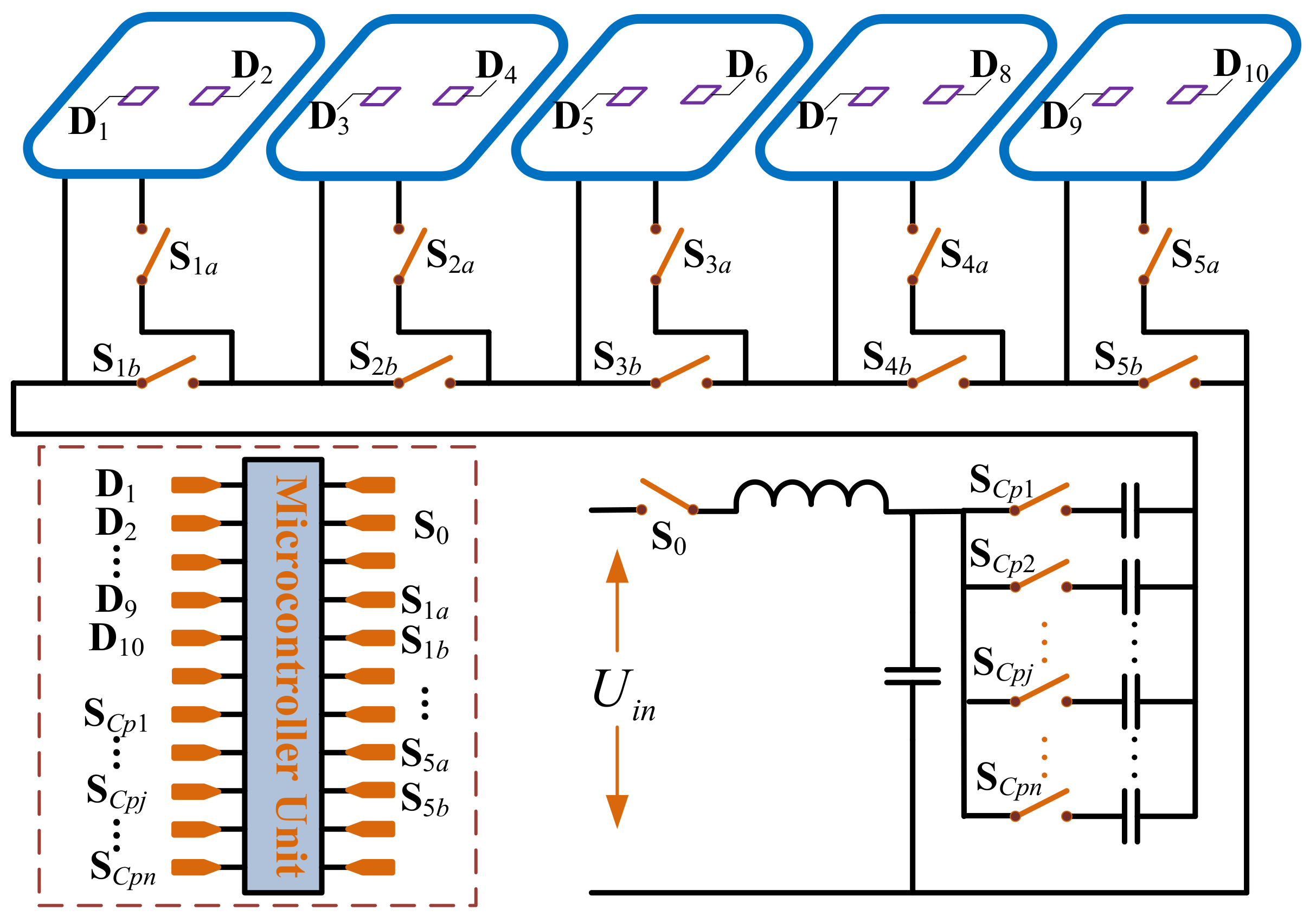
5.1. Topology Design of the Detection and Switching Control in Primary Side

To suppress the fluctuation of the receiving power during the process of the movement, the power stabilization strategy based on the alternating of the energizing mode in different regions is proposed in the following part according to the comparative characteristics of the receiving power varying with the position change of the receiving coil. In the proposed system, the switching control of the transmitting coils depends on the system comparative characteristics of different energizing mode, rather than the physical spacing of the transmitting coils. The regions of different energizing modes are divided according to the system comparative characteristics. The detection sensors are installed at the switching control positions to generate the signal for alternating the energizing modes. When the sensors detect the passing of the EVs, the system will send the instruction to energize the corresponding segmented transmitting coils according to the control strategy. To realize this control conception, the topology of the position detection and switching control in primary side is designed as shown in Figure 8. Except for the high-frequency inverter, the compensation circuit and the transmitting coils, the primary side also contains the position detection devices, the switching control devices and the microcontroller unit. In Figure 8, S0 is the control switch of the inverter. SCp1 to SCpn are the control switches of the multiple capacitors in primary compensation circuit. S1a, S1b to S5a, S5b are the control switches of the multiple segmented transmitting coils. D1 to D10 are the detection sensors for EVs’ positions. Considering the safe distance and the dimensional relationship between the receiving coil and chassis of EVs, the system can contain up to three loads at the same time.

5.2. Control Conception of the Multiple Compensation Capacitors

According to the comparative characteristics of the receiving power varying with the load position for the single load as shown in Figure 7, the intersections of two characteristic curves are selected as the switching control points (the installation positions of the detection sensors) of different energizing modes. When the receiving coil is in the interval [D2k − 1, D2k] (k = 1,...,5), the single energizing mode is applied in the primary side to maintain the higher receiving power. When the receiving coil is in the interval [D2k, D2k + 1] (k = 1,...,4), the double energizing mode is used in the primary side to improve the power drop. During the movement process of the multiple receiving coils, the energizing modes of the multiple transmitting coils are alternated according to the positions of the loads to realize the stabilization of receiving power. The corresponding segmented transmitting coils are energized based on the number and positions of the receiving coils. Hence, the equivalent total inductance in primary side is also changed randomly according the number and relative positions of the energized transmitting coils. According to the circuit modeling before, the equivalent total inductance in primary side is represented as
L p s u m = i = 1 m L p i + 2 i = 1 m h = 1 i 1 M p h p i
Based on the system parameters in Table 1, the mutual inductances between different transmitting coils are calculated and analyzed according to the Neumann formula. As shown in Table 2, except for the adjacent transmitting coils, the mutual inductances between the transmitting coils more than two coils apart are relatively tiny. Hence, only the mutual inductances between the adjacent transmitting coils need to be considered.
Lp represents the inductance of the identical segmented transmitting coils. M12 denotes the mutual inductances between the adjacent transmitting coils. x is the number of the energized transmitting coils. y is the number of the cases of the adjacent coils in all the energized transmitting coils. Equation (15) can be simplified as
L p s u m = x L p + 2 y M 12
Considering actual situations, the length of the receiving coil is shorter than a half even one third of the vehicle’s overall length. After analyzing all the cases of the energized transmitting coils, there are 7 different cases about x and y. The lookup table of Cp-x-y is shown in Table 3. Cp1 to Cp7 represent the value of Cp in primary side for the 7 different existing cases. × represents the nonexistent cases.
According to Equation (4), the expression of Cp is written as
C p i = 1 ω 2 ( x L p + 2 y M 12 L f )
Cpi is related to x and y as shown in Equation (17). x and y are determined by the number and positions of the loads. In order to cooperate with the switching control of the segmented transmitting coils, the compensation capacitor Cpi is also switched based on the values of x and y. Cp1 to Cp7 are designed according to Equation (17). The multiple compensation capacitors are controlled according to the lookup table of Cp-x-y in Table 3.

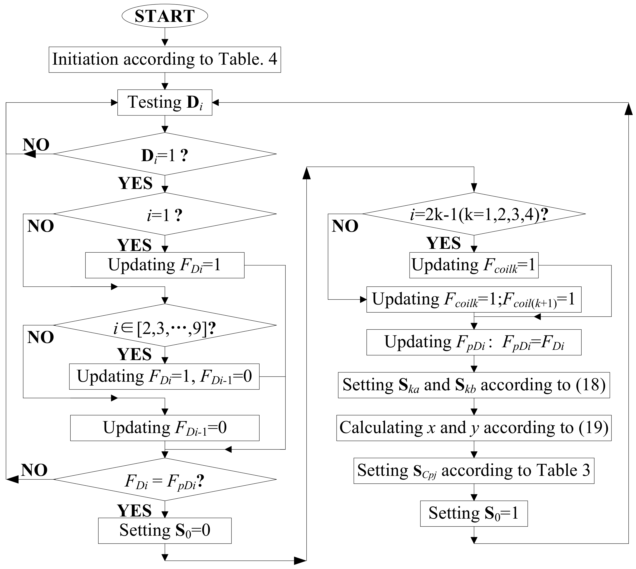
5.3. The Power Stabilization Control Strategy of the Static-Dynamic Hybrid Wireless Charging System

According to the characteristics analysis of the dynamic wireless power transfer system for a single load, the switching points for alternating of the energizing modes in primary side is selected at the intersections of two characteristic curves about the receiving power varying with the receiving position. Hence, the multiple detection positions of switching control are determined for the static-dynamic hybrid wireless charging system with multiple transmitting coils and multiple loads as shown in Figure 9. When the central of the receiving coil reaches the position of the detection sensor, the state parameter Di of the detection sensor jumps from 1 to 0. After the receiving coil passing, Di jumps from 1 to 0. According to monitoring the change of the state of the detection sensors, the number and positions of the loads in the area of the multiple transmitting coils can be deduced.
Firstly, the flags of the real-time state for the detection sensors (FDi, i = 0,...,10), the flags for the previous states for the detection sensors (FpDi), the energizing flags of the receiving coil (Fcoilk, k = 1,...,5), the number of loads (n), the master switch (S0), the switches of transmitting coils (Ska, Skb), the switch states of compensation capacitors (Scpj), x and y are initiated according to Table 4.
Secondly, the outputs (Di) of the detection sensors are monitored in real time. If Di = 0 (i = 1), one load passed the first detection sensor and entered the area [D1, D2). FD1 is changed from 0 to 1. If Di = 0 (i = 2,3,..., 9), one load moved from the area [Di − 1, Di) to the area [Di, Di + 1). FDi is changed from 0 to 1 and FDi-1 is changed from 1 to 0. If Di = 0 (i = 10), one load left the effective wireless charging area. FD9 is changed from 1 to 0.
In order to avoid the duplicate switching actions and contain one-way random movement of the multiple loads, the method is proposed to determine the position change of the loads. The flags of the real-time state for the detection sensors (FDi) and the flags for the previous states for the detection sensors (FpDi) are compared. If FDi is not equal to FpDi, the position of the load is changed. Then S0 is changed from 0 to 1. FDi = 1 means one load is in the area [Di, Di + 1). According to the analysis of the load positions and the concept of the switching control, when a load is in the area [D(2k − 1), D2k) (k = 1,...,5), the energizing flag of the kth transmitting coil Fcoilk is set to 1. When a load is in the area [D2k, D(2k + 1)) (k = 1,...,4), the energizing flags of the kth and the (k + 1)th transmitting coils (Fcoilk and Fcoilk + 1) are set to 1. FpDi is updated by FDi.
Based on the energizing flags (Fcoilk) of the transmitting coils, the switches of transmitting coils are set as
{ S k a = F c o i l k S k b = F c o i l k
After collecting the energizing flags (Fcoilk), the number of the energized transmitting coils (x) and the number of the cases of the adjacent coils in all the energized transmitting coils (y) can be deduce according to
{ x = k = 1 5 F c o i l k y = k = 1 4 ( F c o i l k · F c o i l ( k + 1 ) )
The compensation capacitor Cpj is adjusted by the control switch SCpj according to Table 3. After setting the control switches for the short-segmented transmitting coils and the compensation capacitors, the master switch (S0) is set to 0 and turned on. The switching control and power stabilization strategy for the static-dynamic hybrid wireless charging system with multiple transmitting coils and multiple loads is proposed based on the cycling position detection, the switching control of the transmitting coils and the adjustment control of the compensation circuit in primary side as presented above. The flow of the proposed control strategy for switching control and power stabilization is shown in Figure 10.

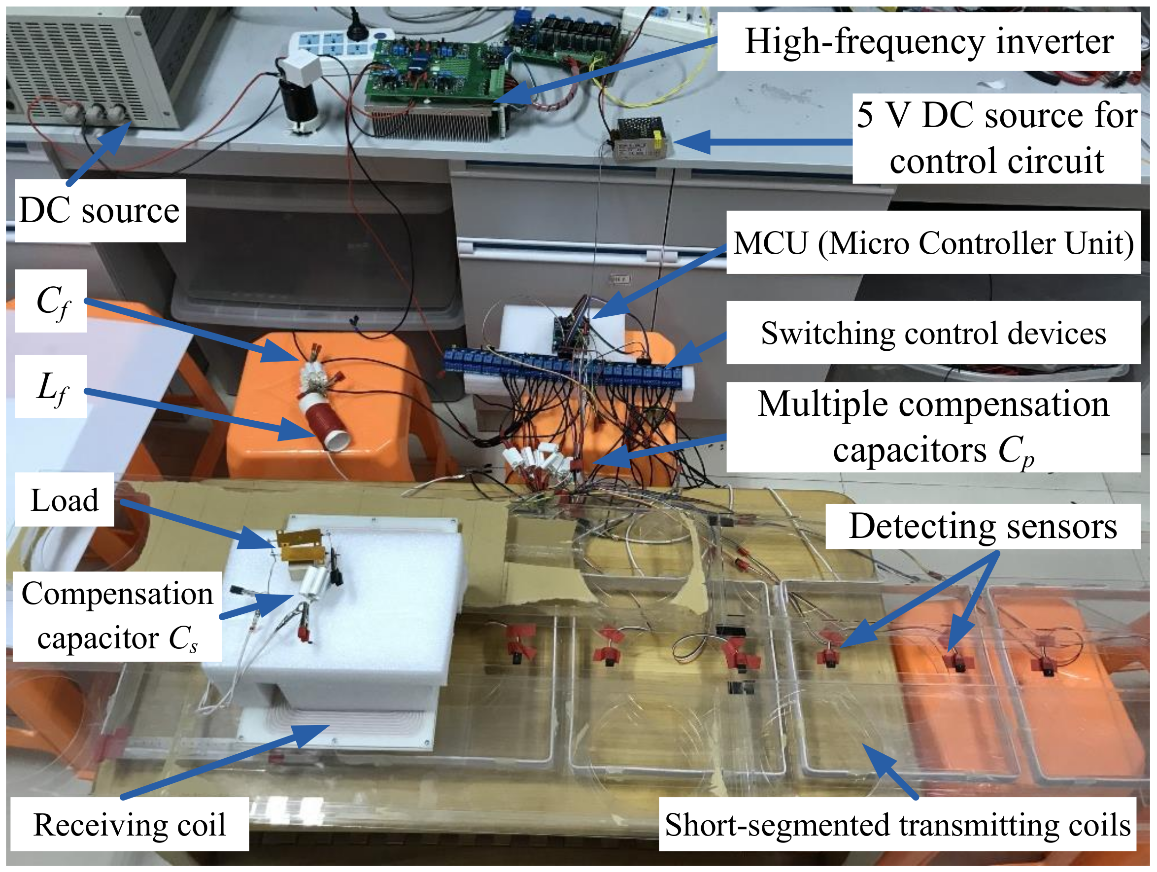
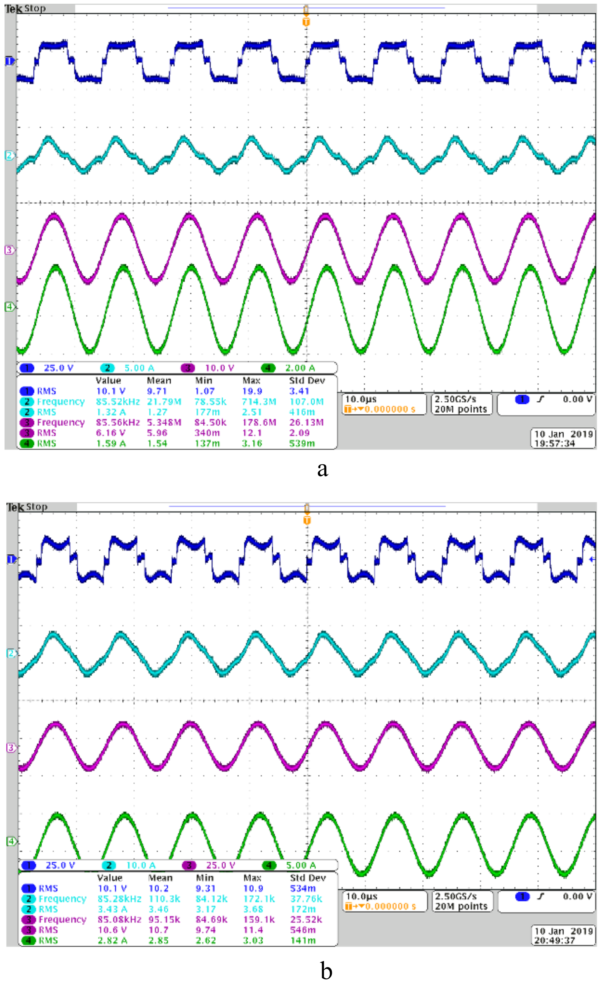
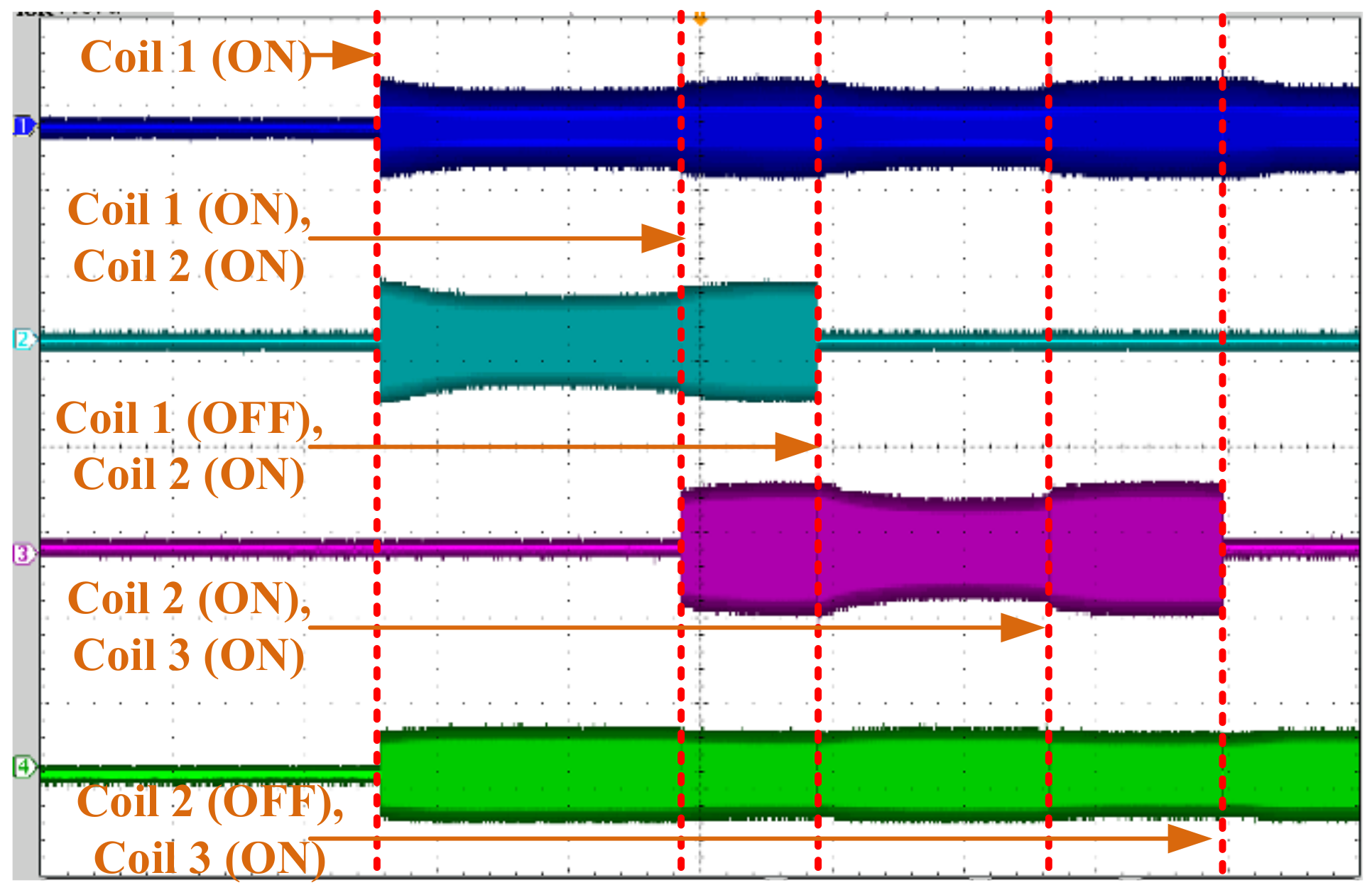
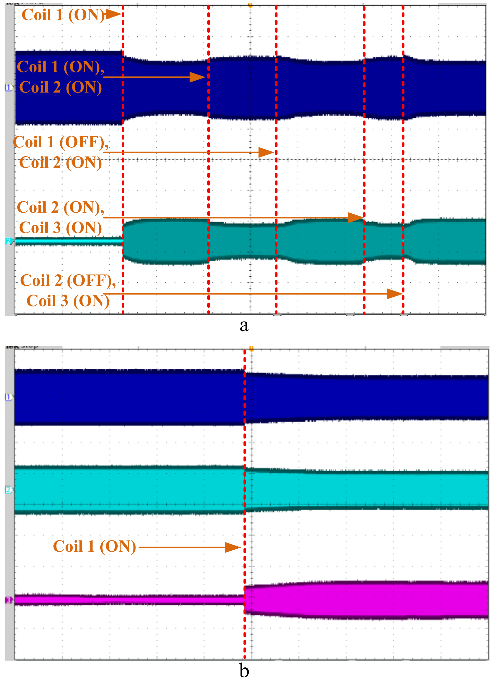
6. Experimental Verification

In order to verify the theoretical analysis, the prototype of the static-dynamic hybrid wireless charging system with multiple transmitting coils and multiple loads is set up as shown in Figure 11. The primary side includes the DC source, the high-frequency inverter, fixed part of primary compensation circuit, multiple switchable compensation capacitors, five segmented transmitting coils, the switching control devices and the MCU (Micro Controller Unit). Up to three loads with receiving coils can be contained in this system. Each receiving circuit consists of the receiving coil, series compensation capacitor and the loads. The output voltage of this paper is 10 V. The operation frequency is 85 kHz. The multiple segmented transmitting coils are space spiral coil identically. The receiving coils are flat spiral coil identically. The dimension parameters of the coils are listed in Table 1. The inductance of the transmitting coil is measured as 33.2 μH at 85 kHz by the LCR meter (HIOKI3522-50). The resistance of the transmitting coil is 31.5 mΩ. The inductance and resistance of the receiving coil are 40.1 μH and 49.8 mΩ respectively. The distance between the centers of two adjacent transmitting coils is 300 mm. The mutual inductance between two adjacent transmitting coils is measured as 2.85μH. Lf in the fixed part of primary compensation circuit is 5.0 μH. According to Equation (3), Cf is designed as 701.2 nF. The measured value of Cf is 701.5 nF. For the single energizing mode, Cp (Cp1) is designed as 124.3 nF. The measured value of Cp1 is 124.8 nF. For the single energizing mode, Cp (Cp2) is designed as 37.1 nF. The measured value of Cp2 is 37.1 nF. Cs (Cs1, Cs2, Cs3) in each receiving circuits is designed as 87.4 nF. The measured values of Cs1, Cs2 and Cs3 are 87.7 nf, 87.1 nf and 88.0 nF respectively. The load resistance is 3.8 Ω.
For the proposed switching control and power stabilization strategy for the static-dynamic hybrid wireless charging system with multiple transmitting coils and multiple loads, the installation positions of the detection sensors should be identified in advance. Cp (Cp1) is applied in the wireless power transfer system with single energizing mode. Cp (Cp2) is applied in the wireless power transfer system with double energizing mode. The experimental comparative characteristics of the receiving power varying with the position of the receiving coil for a single load in different energizing modes is obtained as shown in Figure 12. When the receiving coil is aligned with one transmitting coil, the receiving power of the system with single energizing mode is higher than the one of the system with double energizing mode. When the receiving coil is at the middle position of two adjacent transmitting coils, the receiving power of the system with single energizing mode is significantly lower than the one of the system with double energizing mode. If the single energizing mode is applied, the power fluctuation is nearly 30 W during the movement of the receiving coil as shown in Figure 12. According to the comparative characteristics of the receiving power varying with the position of the receiving coil, the positions of the alternating points of two energizing modes are selected at the intersections (+11 cm and −11 cm) of two characteristic curves. The experimental waveforms of different energizing modes when the receiving coil is at the middle position between two adjacent transmitting coils are shown in Figure 13.
Based on the theoretical analysis before, in order to maintain the stability of the receiving power during the variation of the number and positions of the load, the segmented transmitting coils and the compensation capacitors should be energized in groups. The multiple capacitors in the variable part of the primary compensation circuit are designed according to the cases listed in Table 3, the expression of the compensation capacitors Equation (17) and experimental parameters. The calculation values and the measured values of the multiple capacitors are listed as shown in Table 5.
After selecting the positions of the detection sensors and designing the multiple compensation capacitors, the experimental prototype is installed as shown in Figure 11. According to the proposed control strategy for switching control and power stabilization, all the variables in the proposed strategy are initiated firstly. Ten detection sensors are used to monitoring the position variations of the loads. The MCU with the control strategy collects the information from the detection sensors and adjusts the switching control devices of the segmented transmitting coils and the multiple compensation capacitors. The processed of load accessing are imitated by changing the position of loads. The variations of the currents through the first and the second transmitting coils and the voltage variation of the load during the process of the first load accessing are shown in Figure 14.
After the first load stops at the fifth transmitting coil, during the process of the movement of the second load from the access position to the position aligned with the third transmitting coil, the characteristic curves of the voltages of two loads varying with the position of the second receiving coil is measured and shown in Figure 15a. After the first load stops at the fifth transmitting coil and the second load stops at the third transmitting coil, during the process of the movement of the third load from the access position to the position aligned with the first transmitting coil, the characteristic curve of the voltages of three loads varying with the position of the second receiving coil is measured and shown in Figure 15b.
On the basis of the selection of the positions for the detection sensors, design for the multiple compensation capacitors and the installation of the static-dynamic hybrid wireless charging system, the theoretical analyses especially the proposed control strategy for switching control and power stabilization are verified by the experiments above. The segmented transmitting coils and the multiple compensation capacitors are controlled by the switching devices according to the load positions. Comparing with the single energizing mode, the stability of the receiving power during the movement process of loads is promoted by the proposed strategy of the alternating control between the single energizing mode and the double energizing mode. Especially when then receiving coil is at the middle position of two adjacent transmitting coils, the receiving power is promoted from 9.79 W to 29.9 W. The efficiency is measured based on the voltage of the load, the current through the load, the output voltage and the current of the inverter. When the receiving coil of the single load is at the middle position of two adjacent transmitting coils, comparing with the system of the single energizing mode, the efficiency of the system with the proposed control strategy is promoted from 73.5% to 86.2%. According to the experimental results shown in Figure 14 and Figure 15, during the movement process of each load, the receiving power fluctuations of the dynamic moving load or the static stop load are no more than 10 W.

7. Conclusions

In this paper the static-dynamic hybrid wireless charging system with short-segmented transmitting coils at intersections is introduced. The EVs waiting for the traffic lights at intersections can be charged through the dynamic or static wireless power transfer technology to promote the driving range and decrease the carried batteries. The topology and principle of the proposed static-dynamic hybrid wireless charging system with short-segmented coils at traffic lights are presented. After developing the general circuit model of the static-dynamic hybrid wireless charging system with multi-coupling between the primary and secondary sides, the expressions of the compensation capacitors, the receiving power and the efficiency are deduced. The system characteristics including the mutual inductance and the comparative receiving power varying with the position of the single load are analyzed. The alternating control method for energizing modes in primary side and the adjustment control method for the multiple primary compensation capacitors are put forward. Then the control strategy for the static-dynamic hybrid wireless charging system with multi short-segmented coils and multi loads is proposed to promote the stability of the receiving power. Comparing with the single energizing mode, the receiving power of the system based on the proposed alternating control is more stable during the process of the load movement. Especially comparing with the single energizing mode when the receiving coil is at the middle position of two adjacent transmitting coils, the receiving power is promoted form 9.79 W to 29.9 W. In addition, during the access process of each load, the power fluctuation is lower than 10 W.

Author Contributions

Conceptualization, H.L.; Formal analysis, H.L., L.T., Z.Z. and J.L.; Funding acquisition, L.T.; Methodology, H.L. and M.Z.; Project administration, L.T. and X.H.; Supervision, L.T. and X.H.; Validation, H.L., M.Z., Z.Z. and J.L.; Writing—original draft, H.L.; Writing—review & editing, L.T. and X.H.

Funding

This work was supported in part by State Grid Corporation Science and Technology Project Funding (Selection of Wireless Charging Frequency for Electric Vehicles and Its Impact on Environment), in part by National key R & D project (NO.2018YFB0106300), in part by the National Natural Science Foundation of China (51777028), in part by the Scientific Research Foundation of Graduate School of Southeast University (YBJJ1728) and in part by the Postgraduate Research & Practice Innovation Program of Jiangsu Province (KYCX17-0088).

Acknowledgments

This work was also supported by the China Scholarship Council.

Conflicts of Interest

The authors declare no conflict of interest.

References

  1. Li, S.; Mi, C.C. Wireless Power Transfer for Electric Vehicle Applications. IEEE J. Emerg. Sel. Top. Power Electron. 2015, 3, 4–17. [Google Scholar]
  2. Patil, D.; McDonough, M.K.; Miller, J.M.; Fahimi, B.; Balsara, P.T. Wireless Power Transfer for Vehicular Applications: Overview and Challenges. IEEE Trans. Transp. Electrif. 2018, 4, 3–37. [Google Scholar] [CrossRef]
  3. Bojarski, M.; Asa, E.; Colak, K.; Czarkowski, D. Analysis and control of multiphase inductively coupled resonant converter for wireless electric vehicle charger applications. IEEE Trans. Transp. Electrif. 2017, 3, 312–320. [Google Scholar] [CrossRef]
  4. Bojarski, M.; Asa, E.; Colak, K.; Czarkowski, D. A 25 kW industrial prototype wireless electric vehicle charger. In Proceedings of the 2016 IEEE Applied Power Electronics Conference and Exposition (APEC), Long Beach, CA, USA, 20–24 March 2016; pp. 1756–1761. [Google Scholar]
  5. Bosshard, R.; Kolar, J.W.; Mühlethaler, J.; Stevanović, I.; Wunsch, B.; Canales, F. Modeling and eta-alpha-Pareto Optimization of Inductive Power Transfer Coils for Electric Vehicles. IEEE J. Emerg. Sel. Top. Power Electron. 2015, 3, 50–64. [Google Scholar] [CrossRef]
  6. Keeling, N.A.; Covic, G.A.; Boys, J.T. A unity-power-factor IPT pickup for high-power applications. IEEE Trans. Ind. Electron. 2010, 57, 744–751. [Google Scholar] [CrossRef]
  7. Li, W.; Zhao, H.; Li, S.; Deng, J.; Kan, T.; Mi, C.C. Integrated LCC compensation topology for wireless charger in electric and plug-in electric vehicles. IEEE Trans. Ind. Electron. 2015, 62, 4215–4225. [Google Scholar] [CrossRef]
  8. Zhong, W.X.; Hui, S.Y.R. Maximum energy efficiency tracking for wireless power transfer systems. IEEE Trans. Power Electron. 2015, 30, 4025–4034. [Google Scholar] [CrossRef]
  9. Jiang, Y.; Wang, L.; Wang, Y.; Liu, J.; Wu, M.; Ning, G. Analysis, Design and Implementation of WPT System for EV’s Battery Charging based on Optimal Operation Frequency Range. IEEE Trans. Power Electron. 2018. [Google Scholar] [CrossRef]
  10. Jeong, S.Y.; Kwak, H.G.; Jang, G.C.; Rim, C.T. Living object detection system based on comb pattern capacitive sensor for wireless EV chargers. In Proceedings of the IEEE 2016 IEEE 2nd Annual Southern Power Electronics Conference (SPEC), Auckland, New Zealand, 5–8 December 2016; pp. 1–6. [Google Scholar]
  11. Jeong, S.Y.; Thai, V.X.; Park, J.H.; Rim, C.T. Self-Inductance-Based Metal Object Detection with Mistuned Resonant Circuits and Nullifying Induced Voltage for Wireless EV Chargers. IEEE Trans. Power Electron. 2019, 34, 748–758. [Google Scholar] [CrossRef]
  12. Kim, S.; Park, H.-H.; Kim, J.; Kim, J.; Ahn, S. Design and analysis of a resonant reactive shield for a wireless power electric vehicle. IEEE Trans. Microw. Theory Tech. 2014, 62, 1057–1066. [Google Scholar] [CrossRef]
  13. Choi, S.Y.; Gu, B.W.; Jeong, S.Y.; Rim, C.T. Advances in Wireless Power Transfer Systems for Roadway-Powered Electric Vehicles. IEEE J. Emerg. Sel. Top. Power Electron. 2015, 3, 18–36. [Google Scholar] [CrossRef]
  14. Nagendra, G.R.; Chen, L.; Covic, G.A.; Boys, J.T. Detection of EVs on IPT highways. IEEE J. Emerg. Sel. Top. Power Electron. 2014, 2, 584–597. [Google Scholar] [CrossRef]
  15. Liu, W.; Chau, K.T.; Lee, C.H.T.; Jiang, C.; Han, W. A Switched-Capacitorless Energy-Encrypted Transmitter for Roadway-Charging Electric Vehicles. IEEE Trans. Magn. 2018, 54, 1–6. [Google Scholar]
  16. Zhang, Z.; Ai, W.; Liang, Z.; Wang, J. Topology-Reconfigurable Capacitor Matrix for Encrypted Dynamic Wireless Charging of Electric Vehicles. IEEE Trans. Veh. Technol. 2018, 67, 9284–9293. [Google Scholar] [CrossRef]
  17. Zhao, L.; Thrimawithana, D.J.; Madawala, U.K.; Hu, A.P.; Mi, C.C. A Misalignment-Tolerant Series-Hybrid Wireless EV Charging System with Integrated Magnetics. IEEE Trans. Power Electron. 2019, 34, 1276–1285. [Google Scholar] [CrossRef]
  18. Jeong, S.; Jang, Y.J.; Kum, D. Economic Analysis of the Dynamic Charging Electric Vehicle. IEEE Trans. Power Electron. 2015, 30, 6368–6377. [Google Scholar] [CrossRef]
  19. Limb, B.J.; Asher, Z.D.; Bradley, T.H.; Sproul, E.; Trinko, D.A.; Crabb, B.; Zane, R.; Quinn, J.C. Economic Viability and Environmental Impact of In-Motion Wireless Power Transfer. IEEE Trans. Transp. Electrif. 2018. [Google Scholar] [CrossRef]
  20. Zhang, Z.; Pang, H.; Georgiadis, A.; Cecati, C. Wireless Power Transfer—An Overview. IEEE Trans. Ind. Electron. 2019, 66, 1044–1058. [Google Scholar] [CrossRef]
  21. Zhou, S.; Zhu, C.; Cui, S.; Wang, Z.; Zhou, S.; Chan, C.C. Dynamic Wireless Power Transfer System for Electric Vehicles Employing Multiplexing LCC Modules with Individual Transmitters. IEEE Access 2018, 6, 62514–62527. [Google Scholar] [CrossRef]
  22. Sallan, J.; Villa, J.L.; Llombart, A.; Sanz, J.F. Optimal Design of ICPT Systems Applied to Electric Vehicle Battery Charge. IEEE Trans. Ind. Electron. 2009, 56, 2140–2149. [Google Scholar] [CrossRef]
Figure 1. The schematic diagram of the proposed static-dynamic hybrid wireless charging system.
Energies 12 00607 g001
Figure 2. The structure diagram of the proposed static-dynamic hybrid wireless charging system with segmented coils for multiple EVs.
Energies 12 00607 g002
Figure 3. The general circuit model of the wireless power transfer system with multiple transmitters and multiple receivers.
Energies 12 00607 g003
Figure 4. The schematic diagram of multiple transmitting coil and single receiving coil.
Energies 12 00607 g004
Figure 5. Characteristics of the mutual inductances varying with the position of the single receiving coil.
Energies 12 00607 g005
Figure 6. The comparative characteristics of the equivalent total mutual inductance.
Energies 12 00607 g006
Figure 7. The comparative characteristics of different energizing modes varying with the position of the receiving coil. (a) The normalized receiving power. (b) The efficiency.
Energies 12 00607 g007
Figure 8. The topology design of the position detection and switching control in primary side.
Energies 12 00607 g008
Figure 9. The multiple detection positions of switching control.
Energies 12 00607 g009
Figure 10. The flow of the proposed control strategy for switching control and power stabilization.
Energies 12 00607 g010
Figure 11. The prototype of the static-dynamic hybrid wireless charging system with multiple transmitting coils.
Energies 12 00607 g011
Figure 12. The experimental comparative characteristics of the receiving power varying with the position of the receiving coil.
Energies 12 00607 g012
Figure 13. The experimental waveforms of different energizing modes when the receiving coil is at the middle position between two adjacent transmitting coils. (a) Single energizing mode. CH1 (25 V/div): output voltage of the inverter; CH2 (5 A/div): output current of the inverter; CH3 (10 V/div): voltage of the load; CH4 (2 A/div): current of the load. (b) Double energizing mode. CH1 (25 V/div): output voltage of the inverter; CH2 (10 A/div): output current of the inverter; CH3 (25 V/div): voltage of the load; CH4 (5 A/div): current of the load.
Energies 12 00607 g013
Figure 14. The experimental waveform variations during the process of the first load accessing. (CH1 (25 V/div): The output voltage of the inverter; CH2 (5 A/div): The currents through the first transmitting coil; CH3 (5 A/div): The currents through the second transmitting coil; CH4 (25 V/div): The voltage of the load.).
Energies 12 00607 g014
Figure 15. The characteristic curves of the receiving power of multiple loads varying with the position of the new accessing load. (a) The accessing process of the second load (CH1 (25 V/div): voltage of the first load. CH2 (25 V/div): voltage of the second load.); (b) The accessing process of the third load. (CH1 (25 V/div): voltage of the first load. CH2 (25 V/div): voltage of the second load. CH3 (25 V/div): voltage of the third load.).
Energies 12 00607 g015
Table 1. The parameters of coils.
SymbolslpwplswsN1N2Dh
Values270 mm270 mm300 mm200 mm710300 mm80 mm
Table 2. The mutual inductances between different transmitting coils.
Energies 12 00607 i001
Table 3. The lookup table of Cp-x-y.
x12345
y
0Cp1Cp2Cp3××
1×Cp4Cp5××
2×××Cp6×
3×××Cp7×
4×××××
Table 4. Initiation of the variables.
VariablesFDiFpDiFcoilknS0SkaSkbScpjxy
Value0000111100
Table 5. The calculation values and the measured values of the multiple capacitors.
CpiCp1Cp2Cp3Cp4Cp5Cp6Cp7
Calculation values (nF)124.357.137.162.939.430.131.7
Measured values (nF)124.857.337.162.639.630.232.0

