Abstract
Two-stroke cycle engines have always been prominent due to their distinctive advantage incorporating high power-to-weight ratio, however the drawbacks are poor combustion efficiency, fuel short-circuiting and excessive emission of uHC and CO. These problems are apparent at low-load and speed regions and are the major obstacle to their global acceptance. The deficiencies can be addressed by increasing the in-cylinder average charge temperature employing Exhaust Gas Recirculation (EGR). An experimental study is conducted to investigate the influence of utilizing EGR techniques, including Internal and External EGR, on combustion misfiring occurrence, combustion stability and exhaust emissions using a single cylinder two-stroke SI engine at idling, low and mid-load conditions. From the results, it is observed since the average in-cylinder charge temperature is increased, due to utilizing EGRs, engine’s low and mid-load irregular combustions (misfire) and exhaust emissions are remarkably supressed and almost all of misfire cycles eliminated depending on the percentage of EGRs. In terms of combustion stability, it is agreed in general the application of EGRs improves the cyclic variation of IMEP, Pmax and CA10 compared to conventional operation. However, applying Ex-EGR compared to In-EGR will deteriorate cyclic variability of IMEP and CA10.
1. Introduction
Since the fossil fuel resources are finite and the effect of greenhouse issue, Internal Combustion Engines (ICEs) having high thermal efficiency and lower exhaust gas emission have been always at the point of interest for IEC’s research and development scientists [1,2,3]. There are some irrefutable advantages for two-stroke cycle engines, comprising light weight, simple construction, less components, cheap to manufacturing and the potential to pack almost twice the power-density than that of a four-stroke engine having similar capacity. This makes them unique among any other ICE types [4,5,6,7,8]. Numerous substantial research works were conducted to tackle two-stroke engines main drawback, which is high level of unburned hydrocarbons (uHC) emissions, caused by unstable running operation combined with incomplete combustion known as misfire cycle, especially at light load [9,10,11,12,13,14]. Cycle-to-cycle variation at low and mid-load has long been known as one of the drawbacks in two-stroke cycle engines. This cyclic variation is attributed to lower average charge temperature of the cylinder, as at low-speed and low-load, the amount of energy released per each combustion cycle is too low to maintain the next combustion cycle temperature to be continued without misfiring [15,16,17,18,19,20,21]. Figure 1 represents the typical relationship between the average charge temperature at the start of compression stroke (exhaust port closure temperature, Tepc) and quantity of fresh charge and residual gas. It explains the effect of engine speed in conjunction with average charge temperature for the reference conventional two-stroke cycle engine [22,23,24,25].
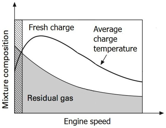
Figure 1.
Variation of average charge temperature at the start of compression (Tepc), quantity of fresh charge and residual gas against engine speed in a typical two-stroke cycle engine [25].
As can be seen from Figure 1 that the Tepc is low when the engine is run at low-speed (hatched region) and high-speed. A high magnitude of Tepc can be reached when the engine speed is beyond the mid-speed but not at engine top-end speed. The reasons for having lower Tepc at engine high speed are attributed to lower amount of available residual gases and shorter available time for mixing of fresh charge and residual gases. It has been found that depending on the engine speed, load and level of Exhaust Gas Recirculation (EGR), it is possible to increase the Tepc in a two-stroke engine due to the mixing of unburned gas introduced into the cylinder and hot residual gas (burned gas) [26,27,28,29,30].
2. Influence of EGR Application
Exhaust port closure temperature (Tepc) should be sufficiently high to achieve a complete combustion at the end of the compression stroke via spark plus ignition. The usage of EGR will result in a higher gas temperature regime throughout the compression process, which in turn speeds up the chemical reactions which will lead to the start of combustion of homogeneously mixed fuel and air mixtures [31,32,33,34,35]. These requirements can be realized by recycling or trapping the burned gases within the cylinder, which the former is called External EGR (Ex-EGR) and the latter is called Internal EGR (In-EGR), respectively. The effect of using EGR on the engine combustion and engine performance has been well studied by many of researchers over a wide range of all ICE types. In general, four major effects of utilizing EGR on combustion characteristics can be explained as follows [7,36,37,38,39,40]:
(1). Charge Heating Effect- The temperature of intake charge will be increased by hot-burned gases.
(2). Heat Capacity Effect-Species in the hot burned gases including carbon dioxide (CO2) and water vapor (H2O) have higher value of heat capacity.
(3). Dilution Effect-lower air/oxygen concentration due to substitution of inert gases existed in the hot burned gases.
(4). Chemical Effect-Hot burned gases consist of some activated radical species, which expedite the chemical reaction of combustion.
This objective of the experimental work is to investigate the influence of internal as well as external EGR on the combustion improvement of a typical spark ignition two-stroke cycle engine. The parameters of interest are: (i) combustion cyclic variability, (ii) misfire occurrence and (iii) exhaust emissions.
3. Engine Specifications
A single cylinder two-stroke, naturally aspirated, liquid-cooled engine is modified to prepare it as a test engine for this work. The specifications are in Table 1.

Table 1.
Experimental engine specifications.
It is equipped with an electronically fuel injection system to provide appropriate air-to-fuel ratio (AFR). A closed loop lambda control system is included to ensure the AFR will be precisely set in compliance with the engine’s ECU settings. Intake air box and Pitot tube are employed to measure the engine’s air consumption. The exhaust piping architecture is developed to be able to utilize some portion of the combustion products to be recycled to part of the intake mixture for the next charge. Combustion burned gases inside of the combustion chamber can be kept in the combustion chamber by contraction of exhaust port area. The high temperature burned gases will be mixed by the new incoming charge, which results in higher temperature and pressure at the end of scavenging process. This strategy of the burned gas utilization is called as Internal EGR (In-EGR). Here one ball type valve (diameter 38 mm) is mounted in the exhaust pipe where it is 50 mm away from engine’s exhausting port downstream side. The valve is designed to restrict the exhaust port area from 0–90%. The setup is in Figure 2.
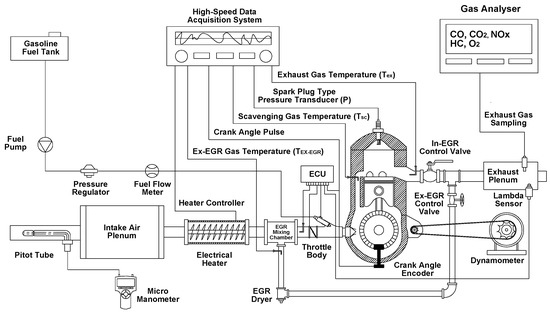
Figure 2.
Schematic view of experimental test rig setup.
A T-joint connection of 25 mm diameter is fitted immediately after the In-EGR to induce a faction of the exhaust gases from the exhaust pipe into the intake runner. This method of burned gas utilization is known as External EGR (Ex-EGR). The technique will not only result in higher intake charge temperature but will also produce different intake charge composition. The burned gases due to Ex-EGR will be mixed with the intake air via one mixing chamber called Ex-EGR mixing chamber. A gate type valve is fitted onto the induction line connecting to the mixing chamber. The induction line is completely insulated to minimize both the convection and the conduction heat transfer losses.
4. Instrumentation and Test Procedure
With reference to Figure 2, several K-type thermocouples (±1 °C accuracy) are fitted at strategic locations to measure for Tex, Tin and Tsc, (engine exhaust gas temperature, intake gas temperature and transfer port gas temperature). One piezoelectric pressure transducer (KISTLER 6117B) is used, in replacement of the engine spark plug, to record for combustion pressure history. The engine crankshaft is coupled to one crank angle encoder (KISTLER 2613B) to measure for engine crank angle rotation (CAD) with 0.2 Degree of resolution. A high-speed data acquisition system (DEWE5000), equipped with software (DEWESoft and DEWECa), is used for data logging. The engine is connected to an eddy-current brake dynamometer (30 kW MAGTROL) via chain and sprockets. Engine fuel consumption is measured using an on-line type fuel flow sensor (ONO SOKKI FP-2240HA). As for engine emission, one portable exhaust gas analyser (EMS 5002) is employed to induce a minute concentration of the HC, CO2 NOx, O2 and CO2. Gasoline 95 (octane rating 95) is used throughout the entire of experimental program.
5. In-Cylinder Gas Thermodynamic and Scavenging Model
It is assumed that the scavenging process in the engine combustion chamber will follow an idealized Isothermal Perfect-Mixing model. According to this model, as the fresh charge enters the cylinder will be mixed immediately with the cylinder charge to create a homogeneous mixture at a constant volume, pressure and temperature. The cylinder walls are adiabatic, the entering charge has the thermodynamic properties of the ambient as well as the two gases involved follow the ideal gas law and have the same molecular weights with identical and constant specific heats [15,35,39,41]. The scavenging efficiency () is exponentially correlated with the corrected delivery ratio (L) in terms of a nonlinear second order semi-empirical equation as explained in Equation (1).
where k0, k1, k2 are scavenging coefficients which represent several types of transfer port geometry. The value of each of these coefficients for loop scavenging having five transfer ports is represented in Table 1 [10,42]. L is the corrected delivery ratio and can be found from Equation (2).
where m•Air is engine intake mass flow rate and R is specific gas constant. Pepc, Vepc and Tepc are pressure, volume and temperature of the engine cylinder gas at the moment when the exhaust port is closed (start of the effective compression). NS is engine speed in rpm and AFR is engine air-to-fuel ratio. When the exhaust port is fully closed by piston (start of effective compression) enthalpy balance equation (Equation (3)) is governed [35,41,43,44] in order to estimate the Tepc.
By assuming equal specific heats for all constituents of the in-cylinder charge [6,15,18,23] (i.e., exhaust port closure mixture, scavenging gas and residual gas; ), the Tepc is now derive as Equation (5):
The residual gas temperature (Tr) is estimated by averaging of the exhaust gas temperature (Tex) and the in-cylinder gas temperature at the exhaust port opening (Tepo) (blow-down gas temperature) as [39]:
Having assumed for adiabatic process during piston descending (expansion) [15,39,41], Tepo can be estimated by Equation (7).
where Tmax and Pmax are data acquired from experimental work and k is polytropic exponent. The exponent k = 1.32 is assumed for the average specific heat capacity ratio of the mixture since quasi-adiabatic process mostly governs the compression and expansion stroke in ICEs engine [15,35,39]. Therefore, Equation (5) can be rewritten as Equation (8):
Finally Tepc is calculated by substitutive Equation (8) into Equations (1) and (2) respectively. Once Tepc is specified, the can be estimated using Equation (1). Consequently, the Tepc and are estimated by a semi-empirical correlation, which is combined with the equation derived from experiment and the enthalpy balance equation at the state of the exhaust port closure.
6. Estimation of In-EGR and Ex-EGR Rate
After completion of the scavenging process (i.e., closure of the exhaust port), some fractions of the burned gas will remain in the combustion chamber. It is known as residual gas, wherein the residual gas ratio (γ) is quantified by Equation (9).
Typically, in all ICEs, especially in two-stroke cycle engines employing conventional scavenging technique, some small amounts of the residual gas are trapped in the combustion chamber permanently. The residual gas can either be increased or decreased depending on the efficiency of the scavenging process but it can never be removed completely [1,41]. This fraction of the residual gas, which is not removable, it called inherent residual gas ratio (γinh). The γinh can be measured when the engine without EGR (i.e., neither In-EGR nor Ex-EGR are applied). Applied residual gas ratio (γap) can be achieved when the engine is operated by means of either In-EGR or Ex-EGR. Hence Equation (9) can now be interpreted as follow [45,46,47,48]:
Normal operating condition (without In/Ex-EGR):
Operating condition with In/Ex-EGR:
When the residual gas ratio (γ) in both applied and inherent conditions is determined, the In-EGR and Ex-EGR rates can be estimated as follows [49,50,51,52,53]:
7. Results and Discussions
7.1. Idling, Low-Load and Mid-Load Misfiring Improvement
In order to investigate for the engine’s combustion stability, misfire index is taken into consideration. This parameter is quantified between one and zero, representing misfire and ideal combustion respectively. In the combustion chamber, it is assumed that a misfire cycle will occur when the indicated mean effective pressure (IMEP) of the combustion cycle is zero.
The engine is run at three speeds and loads with respect to several amounts of both internal and external EGR, as specified in Table 2. As such, three speeds and loads are considered to evaluate the engine’s misfire improvement, that is, 1000 rpm (IMEP = 1 bar; Idling), 2000 rpm (IMEP = 1.5 bar; low-load) and 3000 rpm (IMEP = 2.1 bar; mid-load). All data are recorded for 120 consecutive cycles of the engine operation.
Table 2.
Operating conditions of the engine for misfiring test.
Figure 3 shows the number of misfire occurrence when the engine is operated at 1000 rpm (idling), at various settings of the EGRs. When the engine is run at a normal condition (without In-EGR or Ex-EGR), 31 cycles out of 120 consecutive cycles are observed as misfired, meaning that the misfire occurrence is almost 26 % (refer marking (a)). On the other hand, marking (b) shows by applying just 10% of In-EGR, the misfire occurrence has reduced to 11% i.e., 13 misfired cycles. All of the misfired cycles can be completely eliminated when both In-EGR and Ex-EGR are set at 20% and 12%, respectively as shown by marking (c). The results imply that the EGR utilization will improve the engine combustion stability leading to the reduction in the incomplete combustion (misfiring) at idling condition.
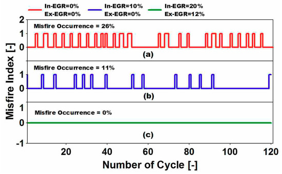
Figure 3.
Influence of In-exhaust gas recirculation (EGR) and Ex-EGR on misfire occurrence at Idling condition (rpm = 1000, IMEP = 1 bar, Tepc = 420 K, AFR = 15).
Figure 4 illustrates the influence of In/Ex-EGR utilization on the misfiring occurrence when the engine is at a higher magnitude of 2000 rpm (low-load). In general, the misfire occurrence is reduced remarkably by increasing either In-EGR or Ex-EGR. Based on Figure 4 marking (a) shows the engine running without EGR generating 26 misfiring over 120 consecutive cycles which is 22% while, this amount has reduced to 9 cycles (misfire occurrence = 8%) when 10% of In-EGR is applied (refer Figure 4, marking (b)). It is observed that by using a combination of both In-EGR and Ex-EGR at 14% and 7%, it will eliminate all the misfired cycles as shown in Figure 4, marking (c). It is worth to mention that the improvement in misfire occurrence is attributed to the increment in the magnitude of Tepc, which is risen from 420 K to 431 K (refer Table 2).
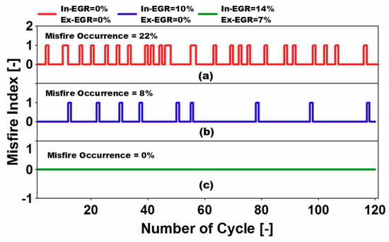
Figure 4.
Influence of In-EGR and Ex-EGR on misfire occurrence at low-load condition (rpm = 2000, IMEP = 1.5 bar, Tepc = 431 K, AFR = 14.5).
In Figure 5 the effect of In/Ex-EGR on misfiring occurrence is again demonstrated when the engine speed is increased to 3000 rpm (mid-load). It is can be observed that when the engine is operated at a higher speed/load, having no applied In/Ex-EGR, the amount of misfire occurrence is been lowered decreasing from 26% to 16%.
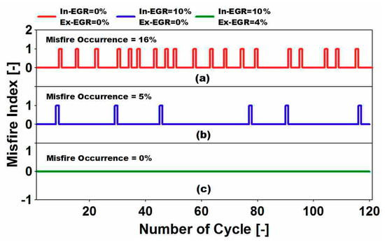
Figure 5.
Influence of In-EGR and Ex-EGR on misfire occurrence at mid-load condition (rpm = 3000, IMEP = 2.1 bar, Tepc = 451 K, AFR = 13.5).
Similarly, the misfire phenomenon can be reduced with the combinational EGRs settings at this engine speed. Almost 16% of the misfire occurrence (19 misfired cycles) is observed when there is no In-EGR and Ex-EGR, as can be seen in Figure 5 marking (a). Similarly the misfire occurrence is reduced significantly by 5% (6 misfire cycles) when 10% of In-EGR is applied. Finally with reference to Figure 5 marking (c), when both In-EGR and Ex-EGR are applied (at 10% and 4% respectively), the misfire occurrence is totally eliminated. In the meantime, it can be seen that the Tepc is now 451 K, which is high enough to assist in the elimination of misfire occurrence.
It is worth to mention that the effect of both In-EGR and Ex-EGR on misfire occurrence is significant at lower speed operation. At lower engine rpm (especially idling), the average temperature of in-cylinder charge is lower than when the engine is at higher engine speed (low/mid-load). Thus, less energy is available for the mixture prior to the compression stroke. Therefore, when the compression stroke ends, the compressed mixture temperature is still not high enough to be ignited by the engine spark plug. In such a scenario misfire will happen. Thus, it can be generalized that utilization of In/Ex-EGR will be more appropriate in the low engine speed and load region
7.2. Combustion Stability and Cyclic Variability Improvement
In order to evaluate statistically the cyclic variation of the engine combustion, parameters such as Coefficient of variation (COV) and Standard Deviation (STD) are used. Here, in-cylinder combustion IMEP and maximum in-cylinder pressure (Pmax) which are pressure-related parameters, together with CA10 (crank angle at 10% of mass fraction burned) which is a combustion-related parameter; are taken into consideration in an effort to examine the combustion stability when the EGRs are applied. All data recorded for 200 consecutive cycles, which is sufficient to provide a steady state condition for the engine during trial.
Figure 6 represents the cyclic variability of CA10, IMEP and Pmax in a conventional operation mode wherein the engine is subjected to 3000 rpm (refer Table 2) but without EGRs. There is huge cyclic variability for CA10, IMEP and Pmax, which is due to poor engine combustion performance. This shows that in such an engine operation condition the cyclic variability of the combustion is significant. Figure 7 presents the cyclic variability of CA10, IMEP and Pmax when the engine is operated at 3000 rpm by applying EGRs (In-EGR = 10 %, Ex-EGR = 4 %) as described in Table 2. Here COVIMEP, COVPmax and STDCA10 are decreased significantly. The improvement in the cyclic variability of IMEP is more considerable compared to the other parameters by reduction in COVIMEP from 22.14 to 2.5.
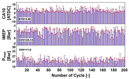
Figure 6.
Cyclic variation of CA10, IMEP and Pmax in conventional operation (rpm = 3000, IMEP = 2.1 bar, Tepc = 385 K, In-EGR = 0, Ex-EGR = 0).
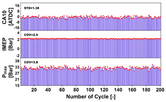
Figure 7.
Cyclic variation of CA10, IMEP and Pmax with EGR utilization (rpm = 3000, IMEP = 2.1 bar, Tepc = 451 K, In-EGR = 10 %, Ex-EGR = 4 %).
For this part of experiment, the cyclic variation of Pmax, CA10 and IMEP are examined in relation to In-EGR and Ex-EGR changes at 3000 rpm (mid-load), based on the operating conditions as explained in Table 3. As can be seen in Figure 8 and Figure 9 the utilization of In-EGR and Ex-EGR improves the cyclic variation of Pmax (COVPmax) meaning that when the percentage of In-EGR and Ex-EGR increases the COVPmax will decrease accordingly. Therefore, it can be deduced that cyclic variation of Pmax is inversely proportional to the concentration of both In-EGR and Ex-EGR. Furthermore, it should be noted that Pmax is more influenced by In-EGR changes since in the case of In-EGR the slope ratio for curve of fit in both Figure 8 and Figure 9 are more than that of Ex-EGR. The reason for this trend can be explained as: In the case of In-EGR the most dominant effect is the charge heating effect wherein both pressure and temperature at the exhaust port closure (Pepc, Tepc) will increase since the percentage of In-EGR is raised therefore it establishes a complete cycle of combustion. Furthermore, owing to the impact of the charge heating effect and the contraction of the exhaust port area by the In-EGR valve, Pepc will increase tremendously. Consequently, Tepc and heat release rate will be increased. In Ex-EGR, the most dominant effects are those of thermal and dilution effects. Utilizing Ex-EGR increases the specific heat capacity of the in-cylinder charge. However, the Tepc is increased slightly, the mixture takes more time to heat up. Additionally, the overall reaction rate of combustion will be suppressed due to substitute of CO2 and H2O instead of O2 (dilution effect) [3,6].
Table 3.
Engine operating conditions for cyclic variability investigation.
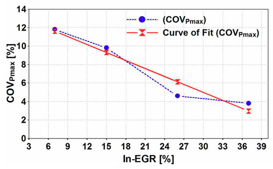
Figure 8.
Cyclic variability of Pmax due to variation of In-EGR setting (rpm = 3000, IMEP = 2.1 bar, Tepc = 425–530 K).
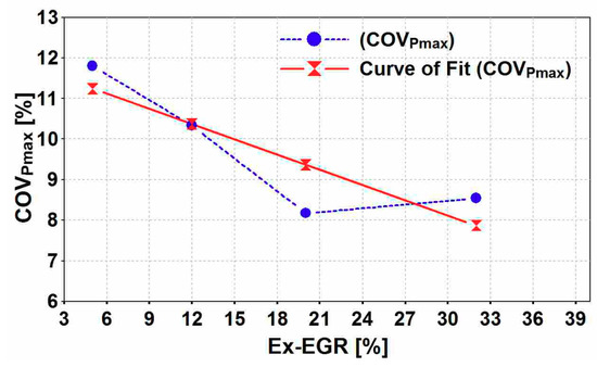
Figure 9.
Cyclic variability of Pmax due to variation of Ex-EGR setting (rpm = 3000, IMEP = 2.1 bar, Tepc = 425–530 K).
Figure 10 and Figure 11 represent the cyclic variability of CA10 (STDCA10) with respect to In-EGR and Ex-EGR variations. As illustrated in Figure 10, STDCA10 decreases when In-EGR rate increases. In contrast, STDCA10 is increased when Ex-EGR increases. Even though In-EGR improves the cyclic variability of CA10, Ex-EGR seems to deteriorate it. Correspondingly, it is thought that STDCA10 is directly proportional with percentage of Ex-EGR while it is inversely proportional with the percentage of In-EGR. Furthermore, the STDCA10 is more sensitive to Ex-EGR changes rather than In-EGR, as it can be clearly interpreted from the slope ratio of the curves of fit in Figure 10 and Figure 11.
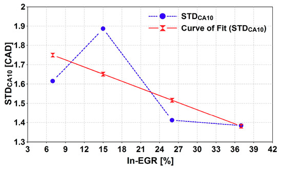
Figure 10.
Cyclic variability of CA10 with In-EGR setting [rpm = 3000, IMEP = 2.1 bar, Tepc = 425–530 K].
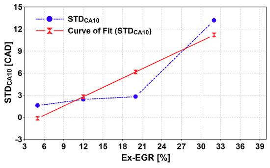
Figure 11.
Cyclic variability of CA10 due to variation of Ex-EGR setting (rpm = 3000, IMEP = 2.1 bar, Tepc = 525–530 K).
The main reason for observing a contrary behaviour of STDCA10 in conjunction with In/Ex-EGR can be attributed to the different dominant effect of each EGR strategies as explained earlier. The dominant effects in In-EGR is charge-heating effect while in Ex-EGR thermal and dilution effects are dominant. Even though the CA10 (crank angle at 10% of mass fraction burned) is basically a combustion-related parameter, in the case of In-EGR application it tends to behaves as a pressure-related parameter. As in Figure 10 it can be clearly understood the STDCA10 is mostly affected by increasing the in-cylinder pressure rise which caused by In-EGR application. Other words, when the percentage of In-EGR goes up it helps to improve the STDCA10 since the charge heating effect and more importantly the forced backpressure caused by exhaust port blockage (In-EGR valve closure) are accounted for increasing in-cylinder peak pressure and temperature. Accordingly, it makes the variation of CA10 smoothen. On the other hand, when the Ex-EGR is applied the CA10 behave as a combustion-related parameter and the dominant effects are those which are influencing the in-cylinder charge composition especially dilution effect which mainly supress the overall reaction rate (heat release) in the combustion chamber. Therefore, when the Ex-EGR increases the variation of CA10 tends to be deteriorated. It means if the Ex-EGR is applied separately it will result in a more cyclic variability for the engine combustion which makes the instability of combustion even worse in the higher percentage of Ex-EGR.
The influence of In/Ex-EGR on the cyclic variability of IMEP (COVIMEP) is illustrated in both of Figure 12 and Figure 13. In Figure 12 COVIMEP is decreased when the In-EGR percentage is raised. But it will become higher as Ex-EGR is increased, as shown in Figure 13. Here it seems COVIMEP is directly proportional with change in Ex-EGR and is inversely proportional with the variation of In-EGR. The trend indicates that COVIMEP is more sensitive to the variation of Ex-EGR rather than In-EGR, as it is can be clearly seen by examining the slope ratio of curves of fit.
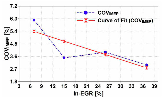
Figure 12.
Cyclic variability of IMEP due to variation of In-EGR setting (rpm = 3000, IMEP = 2.1 bar, Tepc = 525–530 K).
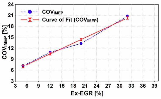
Figure 13.
Cyclic variability of IMEP due to variation of Ex-EGR setting (rpm = 3000, IMEP = 2.1 bar, Tepc = 525–530 K)
Consequently, the major difference between In-EGR and Ex- EGR strategies is that in the In-EGR the charge-heating effect is more considerable because it pressurizes the combustion chamber considerably leading to higher Pepc and Tepc. Though in-cylinder charge composition will change (due to thermal and dilution effects) with In-EGR, it is not significant as compared to changes in Tepc, which is more considerable. In the other hand, Ex-EGR will just mix burned gases to the intake charge leading to changes in in-cylinder charge composition and temperature. In this case the increase in the mixture temperature Tepc will not be considerable while the effect of changes in specific heats (thermal effect) and lack of oxygen (dilution effect) will be important significantly [3,6].
7.3. Idling, Low-Load and Mid-Load Emissions Improvement
In order to examine for the engine exhaust emissions characteristics, it is run at three speeds including 1000 rpm (idling), 2000 rpm (low-load) and 3000 rpm (mid-load) corresponding as identically same as aforementioned section test point conditions (refer Table 2). The exhaust gas concentrations are measured in two states of the engine operation condition. Firstly the state as such a conventional engine operation (without EGR) and secondly the state with application of EGR (combined effect of In/Ex-EGR, refer Table 2). For each of these states the engine is operated in three different speeds (1000, 2000 and 3000 rpm)
Figure 14 represents the variation of uHC and CO emissions against engine speed before and after EGR application. The concentration of both uHC and CO is lowered when EGR applied. From the trend shown it can be interpreted that rate of variations in uHC and CO concentration decrease with the increased in speed. However, engine speed does not impair significantly on the emission concentration of CO when the EGRs are applied. As discussed earlier, since the incomplete combustion cycles (i.e., misfire cycle) are eliminated, due to the using of In/Ex-EGR, the exhaust constituents such as uHC and CO are subjected to change. Having an improved combustion (completed combustion) will result in lower concentration of uHC and CO.
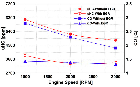
Figure 14.
Influence of In/Ex-EGR on uHC and CO concentrations at idling and low/mid-load settings (rpm = 1000-3000, IMEP = 1-2.1 bar, Tepc = 385-530 K, AFR = 14–16).
Figure 15 presents the variation of NOX, CO2 and O2 emissions against the speed before and after EGR is applied. From the results the concentrations of NOX, CO2 and O2 decrease for all three speeds, however the improvements do not follow the trend as observed earlier for uHC and CO. From the of exhaust emission the EGR application for this type of engine at idling, low-load and mid-load regions mainly affect the reduction in the concentration of uHC and CO, more than that of NOX, CO2 and O2.
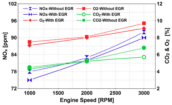
Figure 15.
Influence of In/Ex-EGR on NOx, CO2 and O2 concentrations at idling and low/mid-load settings (rpm = 1000–3000, IMEP = 1–2.1 bar, Tepc = 385–530 K, AFR = 14–16).
8. Conclusion
An experimental study was conducted to investigate the influence of In-EGR and Ex-EGR on the combustion parameters of a spark ignition two-stroke cycle engine for which combustion cyclic variability, misfire occurrence and exhaust emissions were examined. The outcomes of the investigation are summarized as follows:
- The overall effect of EGR is to increase the cylinder charge temperature, which has proven to produce higher exhaust port closure temperature (Tepc) resulting in lower misfiring cycles.
- Reduction in the misfire occurrence due to EGR is apparent at the engine’s lower engine speed region.
- As for average charge temperature (Tepc), In-EGR is more effective than Ex-EGR. It not only increases the Tepc but also increase the pressure of cylinder at the start of combustion (Pepc).
- Both In-EGR and Ex-EGR improve the cyclic variability of the combustion parameters, specifically the IMEP.
- The cyclic variability of CA10, IMEP and Pmax will be further improved by applying In-EGR. Ex-EGR will impair cyclic variability of CA10, IMEP but will improve Pmax.
- The application of EGR offers a significant means to improve and eliminate low and mid load misfire combustion of spark ignition two-stroke cycle engine leading to emission reduction.
Author Contributions
A.M.A., has written the paper context and performed the experimental work alongside results presentation. A.P., V.E. and M.F.M.S. have carried out the design of experiment in the simulation.
Acknowledgments
The authors would like to acknowledge the Universiti Teknologi Malaysia (UTM) for financial support under the research university grant Q.J130000.3509.06G97.
Conflicts of Interest
The authors declare no conflict of interest.
Glossary
| a/bTDC | after/before top dead center |
| AFR | engine air-to-fuel ratio center |
| CO2 | carbon dioxide |
| COV | coefficient of variation |
| CA10 | crank angle at 10% of mass fraction burned |
| Ex-EGR | external exhaust gas recirculation |
| HCCI | homogeneous charge compression ignition |
| IMEP | indicated mean effective pressure |
| In-EGR | internal exhaust gas recirculation |
| K0, K1, K2 | scavenging coefficients |
| k | heat capacity ratio |
| Lap | applied corrected delivery ratio |
| Linh | inherent corrected delivery ratio |
| m•fuel | fuel mass flow rate |
| Mdel | mass of fresh charge delivered |
| Mtr | mass of total gas trapped |
| NOX | nitric oxides |
| Ns | engine speed in RPM |
| NTC | negative temperature coefficient |
| Pepc | in-cylinder pressure at exhaust port closure |
| Pmax | maximum in-cylinder pressure |
| STD | standard deviation |
| R | specific gas constant |
| Tex | exhaust gas temperature |
| Tepc | in-cylinder gas temperature at exhaust port closure |
| Tepo | in-cylinder gas temperature at exhaust port opening |
| Tsc | scavenging gas temperature |
| Tr | residual gas temperature |
| uHC | unburned hydrocarbon |
| Vepc | sweep volume at exhaust port closure |
| γinh | inherent residual gas ratio |
| γap | applied residual gas ratio |
| inherent scavenging efficiency | |
| applied scavenging efficiency |
References
- Benajes, J.; Novella, R.; De Lima, D.; Tribotté, P.; Quechon, N.; Obernesser, P.; Dugue, V. Analysis of the combustion process, pollutant emissions and efficiency of an innovative 2-stroke HSDI engine designed for automotive applications. Appl. Therm. Eng. 2013, 58, 181–193. [Google Scholar] [CrossRef]
- Duret, P. A New Generation of Engine Combustion Processes for the Future?: Proceedings of the International Congress, Held in Rueil-Malmaison, France, November, 26–27, 2001; Editions Technip: Rueil-Malmaison, France, 2002. [Google Scholar]
- Mahmoudzadeh Andwari, A.; Abdul Aziz, A.; Muhamad Said, M.F.; Abdul Latiff, Z. An experimental study on the influence of EGR rate and fuel octane number on the combustion characteristics of a CAI two-stroke cycle engine. Appl. Therm. Eng. 2014, 71, 248–258. [Google Scholar] [CrossRef]
- Ishibashi, Y. Basic Understanding of Activated Radical Combustion and Its Two-Stroke Engine Application and Benefits; SAE Paper 2000-01-1836; SAE International: Warrendale, PA, USA, 2000. [Google Scholar]
- Mahmoudzadeh Andwari, A.; Aziz, A.A.; Said, M.F.M.; Esfahanian, V.; Latiff, Z.A.; Said, S.N.M. Effect of internal and external EGR on cyclic variability and emissions of a spark ignition two-stroke cycle gasoline engine. J. Mech. Eng. Sci. 2017, 11, 3004–3014. [Google Scholar] [CrossRef]
- Mahmoudzadeh Andwari, A.; Aziz, A.A.; Said, M.F.M.; Latiff, Z.A. Experimental investigation of the influence of internal and external EGR on the combustion characteristics of a controlled auto-ignition two-stroke cycle engine. Appl. Energy 2014, 134, 1–10. [Google Scholar] [CrossRef]
- Zhao, H. HCCI and CAI Engines for the Automotive Industry; Woodhead Pub: Cambridge, UK, 2007. [Google Scholar]
- Zhao, H.; Ladommatos, N. Engine Combustion Instrumentation and Diagnostics; Society of Automotive Engineers: Warrendale, PA, USA, 2001; Volume 842. [Google Scholar]
- Asai, M.; Kurosaki, T.; Okada, K. Analysis on Fuel Economy Improvement and Exhaust Emission Reduction in a Two-Stroke Engine by Using an Exhaust Valve; SAE Paper 951764; SAE International: Warrendale, PA, USA, 1995. [Google Scholar]
- Blair, G.P.; Kenny, R.G. Further Developments in Scavenging Analysis for Two-Cycle Engines; SAE International: Warrendale, PA, USA, 1980. [Google Scholar]
- Fang, Q.; Fang, J.; Zhuang, J.; Huang, Z. Influences of pilot injection and exhaust gas recirculation (EGR) on combustion and emissions in a HCCI-DI combustion engine. Appl. Therm. Eng. 2012, 48, 97–104. [Google Scholar] [CrossRef]
- Mahmoudzadeh Andwari, A.; Azhar, A.A. Homogenous Charge Compression Ignition (HCCI) Technique: A Review for Application in Two-Stroke Gasoline Engines. Appl. Mech. Mater. 2012, 165, 53–57. [Google Scholar]
- Mahmoudzadeh Andwari, A.; Aziz, A.A.; Muhamad Said, M.F.; Abdul Latiff, Z. Controlled Auto-Ignition Combustion in a Two-Stroke Cycle Engine Using Hot Burned Gases. Appl. Mech. Mater. 2013, 388, 201–205. [Google Scholar] [CrossRef]
- Mahmoudzadeh Andwari, A.; Pesiridis, A.; Esfahanian, V.; Salavati-Zadeh, A.; Karvountzis-Kontakiotis, A.; Muralidharan, V. A Comparative Study of the Effect of Turbocompounding and ORC Waste Heat Recovery Systems on the Performance of a Turbocharged Heavy-Duty Diesel Engine. Energies 2017, 10, 1087. [Google Scholar] [CrossRef]
- Blair, G.P. The Basic Design of Two-Stroke Engines; Society of Automotive Engineers: SAE International: Warrendale, PA, USA, 1990. [Google Scholar]
- Duret, P. A New Generation of Two-Stroke Engines for the Future?: Proceedings of the International Seminar Held in Rueil-Malmaison, France, November 29-30, 1993; Éditions Technip: Rueil-Malmaison, France, 1993. [Google Scholar]
- Duret, P.; Moreau, J.-F. Reduction of Pollutant Emissions of the IAPAC Two-Stroke Engine with Compressed Air Assisted Fuel Injection; SAE Paper 900801; SAE International: Warrendale, PA, USA, 1990. [Google Scholar]
- Ishibashi, Y.; Asai, M. Improving the Exhaust Emissions of Two-Stroke Engines by Applying the Activated Radical Combustion; SAE Paper 960742; SAE International: Warrendale, PA, USA, 1996. [Google Scholar]
- Mahmoudzadeh Andwari, A.; Aziz, A.A.; Said, M.F.M.; Latiff, Z.A. A Converted Two-Stroke Cycle Engine for Compression Ignition Combustion. Appl. Mech. Mater. 2014, 663, 331–335. [Google Scholar] [CrossRef]
- Mahmoudzadeh Andwari, A.; Aziz, A.A.; Said, M.F.M.; Latiff, Z.A.; Ghanaati, A. Influence Of Hot Burned Gas Utilization On The Exhaust Emission Characteristics Of A Controlled Auto-Ignition Two-Stroke Cycle Engine. Int. J. Automot. Mech. Eng. 2015, 11, 2229–8649. [Google Scholar]
- Mahmoudzadeh Andwari, A.; Pesiridis, A.; Karvountzis-Kontakiotis, A.; Esfahanian, V. Hybrid electric vehicle performance with organic rankine cycle waste heat recovery system. Appl. Sci. 2017, 7, 437. [Google Scholar] [CrossRef]
- Nishi, M.; Kanehara, M.; Iida, N. Assessment for innovative combustion on HCCI engine by controlling EGR ratio and engine speed. Appl. Therm. Eng. 2016, 99, 42–60. [Google Scholar] [CrossRef]
- Nishida, K.; Sakuyama, H.; Kimijima, T. Improvement of Fuel Economy Using a New Concept of Two-Stroke Gasoline Engine Applying Stratified-Charge Auto-Ignition; The Automotive Research Association of India: India, 2009. [Google Scholar]
- Noguchi, M.; Tanaka, Y.; Tanaka, T.; Takeuchi, Y. A Study on Gasoline Engine Combustion by Observation of Intermediate Reactive Products during Combustion; SAE Paper 790840; SAE International: Warrendale, PA, USA, 1979. [Google Scholar]
- Onishi, S.; Jo, S.H.; Shoda, K.; Jo, P.D.; Kato, S. Active Thermo-Atmosphere Combustion (ATAC)—A New Combustion Process for Internal Combustion Engines; SAE Paper 790501; SAE International: Warrendale, PA, USA, 1979. [Google Scholar]
- Ozdor, N.; Dulger, M.; Sher, E. Cyclic Variability in Spark Ignition Engines A Literature Survey; SAE International: Warrendale, PA, USA, 1994. [Google Scholar]
- Salvi, B.L.; Subramanian, K.A. Experimental investigation on effects of exhaust gas recirculation on flame kernel growth rate in a hydrogen fuelled spark ignition engine. Appl. Therm. Eng. 2016, 107, 48–54. [Google Scholar] [CrossRef]
- Takei, T.; Iida, N. Study on Auto-Ignition and Combustion Completion of n-Butane in a Two-stroke Homogeneous Charge Compression Ignition (HCCI) Engine; SAE Paper 2002-32-1786; SAE International: Warrendale, PA, USA, 2002. [Google Scholar]
- Yao, M.; Zheng, Z.; Liu, H. Progress and recent trends in homogeneous charge compression ignition (HCCI) engines. Prog. Energy Combust. Sci. 2009, 35, 398–437. [Google Scholar] [CrossRef]
- Zhang, Y.; Zhao, H.; Ojapah, M.; Cairns, A. CAI combustion of gasoline and its mixture with ethanol in a 2-stroke poppet valve DI gasoline engine. Fuel 2013, 109, 661–668. [Google Scholar] [CrossRef]
- Yu, X.; Wu, H.; Du, Y.; Tang, Y.; Liu, L.; Niu, R. Research on cycle-by-cycle variations of an SI engine with hydrogen direct injection under lean burn conditions. Appl. Therm. Eng. 2016, 109, 569–581. [Google Scholar] [CrossRef]
- Mahmoudzadeh Andwari, A.; Said, M.F.M.; Aziz, A.A.; Esfahanian, V.; Salavati-Zadeh, A.; Idris, M.A.; Perang, M.R.M.; Jamil, H.M. Design, Modeling and Simulation of a High-Pressure Gasoline Direct Injection (GDI) Pump for Small Engine Applications. J. Mech. Eng. 2018, 1, 107–120. [Google Scholar]
- Mahmoudzadeh Andwari, A.; Said, M.F.M.; Aziz, A.A.; Esfahanian, V.; Baker, M.R.A.; Perang, M.R.M.; Jamil, H.M. A Study on Gasoline Direct Injection (GDI) Pump System Performance using Model-Based Simulation. J. Soc. Automot. Eng. Malays. 2018, 2, 14–22. [Google Scholar]
- Iida, N.; Yamasaki, Y.; Sato, S.; Kumano, K.; Kojima, Y. Study on Auto-Ignition and Combustion Mechanism of HCCI Engine; SAE Paper 2004-32-0095; SAE International: Warrendale, PA, USA, 2004. [Google Scholar]
- Heywood, J.B.; Sher, E.; Engineers, S.O.A. The Two-Stroke Cycle Engine: Its Development, Operation, and Design; Taylor & Francis: New York, NY, USA, 1999. [Google Scholar]
- Zhang, Y.; Zhao, H.; Ojapah, M.; Cairns, A. Experiment and Analysis of a Direct Injection Gasoline Engine Operating with 2-Stroke and 4-Stroke Cycles of Spark Ignition and Controlled Auto-Ignition Combustion; SAE International: Warrendale, PA, USA, 2011. [Google Scholar]
- Karvountzis-Kontakiotis, A.; Mahmoudzadeh Andwari, A.; Pesyridis, A.; Russo, S.; Tuccillo, R.; Esfahanian, V. Application of Micro Gas Turbine in Range-Extended Electric Vehicles. Energy 2018, 147, 351–361. [Google Scholar] [CrossRef]
- Iida, N. Combustion Analysis of Methanol-Fueled Active Thermo-Atmosphere Combustion (ATAC) Engine Using a Spectroscopic Observation; SAE Paper 940684; SAE International: Warrendale, PA, USA, 1994. [Google Scholar]
- Heywood, J.B. Internal Combustion Engine Fundamentals; McGraw-Hill: New York, NY, USA, 1988. [Google Scholar]
- Ghanaati, A.; Mat Darus, I.Z.; Farid, M.; Said, M.; Mahmoudzadeh Andwari, A. A Mean Value Model For Estimation Of Laminar And Turbulent Flame Speed In Spark-Ignition Engine. Int. J. Automot. Mech. Eng. 2015, 11, 2229–8649. [Google Scholar] [CrossRef]
- Blair, G.P.; Committee, S.P.A.S.P. Advances in Two-Stroke Cycle Engine Technology; Society of Automotive Engineers: SAE International: Warrendale, PA, USA, 1989. [Google Scholar]
- Nuti, M.; Martorano, L. Short-Circuit Ratio Evaluation in the Scavenging of Two-Stroke S.I. Engines; SAE International: Warrendale, PA, USA, 1985. [Google Scholar]
- Tsuchiya, K.; Hirano, S.; Okamura, M.; Gotoh, T. Emission Control of Two-Stroke Motorcycle Engines by the Butterfly Exhaust Valve; SAE Paper 800973; SAE International: Warrendale, PA, USA, 1980. [Google Scholar]
- Iijima, A.; Yoshida, K.; Shoji, H. A Comparative Study of HCCI and ATAC Combustion Characteristics Based on Experimentation and Simulations Influence of the Fuel Octane Number and Internal EGR on Combustion; SAE International: Warrendale, PA, USA, 2005. [Google Scholar]
- Liu, H.; Zhang, P.; Li, Z.; Luo, J.; Zheng, Z.; Yao, M. Effects of temperature inhomogeneities on the HCCI combustion in an optical engine. Appl. Therm. Eng. 2011, 31, 2549–2555. [Google Scholar] [CrossRef]
- Goto, K.; Iijima, A.; Yoshida, K.; Shoji, H. Analysis of the Characteristics of HCCI Combustion and ATAC Combustion Using the Same Test Engine; SAE International: Warrendale, PA, USA, 2004. [Google Scholar]
- García, M.T.; Aguilar, F.J.J.-E.; Lencero, T.S.; Villanueva, J.A.B. A new heat release rate (HRR) law for homogeneous charge compression ignition (HCCI) combustion mode. Appl. Therm. Eng. 2009, 29, 3654–3662. [Google Scholar] [CrossRef]
- Duret, P.; Ecomard, A.; Audinet, M. A New Two-Stroke Engine with Compressed-Air Assisted Fuel Injection for High Efficiency low Emissions Applications; SAE Paper 880176; SAE International: Warrendale, PA, USA, 1988. [Google Scholar]
- Zhang, Y.; Zhao, H.; Ojapah, M.; Cairns, A. Effects of Injection Timing on CAI Operation in a 2/4-Stroke Switchable GDI Engine. SAE Int. J. Engines 2011, 5, 67–75. [Google Scholar] [CrossRef]
- Liu, Y.; Zhang, F.; Zhao, Z.; Dong, Y.; Ma, F.; Zhang, S. Study on the synthetic scavenging model validation method of opposed-piston two-stroke diesel engine. Appl. Therm. Eng. 2016, 104, 184–192. [Google Scholar] [CrossRef]
- Ishibashi, Y.; Asai, M. A Low Pressure Pneumatic Direct Injection Two-Stroke Engine by Activated Radical Combustion Concept; SAE Paper 980757; SAE International: Warrendale, PA, USA, 1998. [Google Scholar]
- Duret, P.; Venturi, S.P. Automotive Calibration of the IAPAC Fluid Dynamically Controlled Two-Stroke Combustion Process; SAE Paper 960363; SAE International: Warrendale, PA, USA, 1996. [Google Scholar]
- Duret, P.; Dabadie, J.-C.; Lavy, J.; Allen, J.; Blundell, D.; Oscarsson, J.; Emanuelsson, G.; Perotti, M.; Kenny, R.; Cunningham, G. The Air Assisted Direct Injection ELEVATE Automotive Engine Combustion System; SAE Paper 2000-01-1899; SAE International: Warrendale, PA, USA, 2000. [Google Scholar]


© 2019 by the authors. Licensee MDPI, Basel, Switzerland. This article is an open access article distributed under the terms and conditions of the Creative Commons Attribution (CC BY) license (http://creativecommons.org/licenses/by/4.0/).