Optimization Study on Fluids for the Gravity-Driven Organic Power Cycle


Abstract
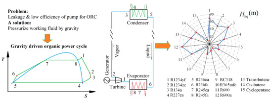
1. Introduction
2. Theoretical Method
2.1. Introduction of Gravity-Driven Organic Power Cycle (GDOPC)
2.2. Considered Fluids
2.3. Analysis Method of GDOPC
3. Results and Discussion
3.1. Comparison between GDOPC and Organic Rankine Cycle (ORC)
3.2. Analysis on Pressure Drop and Heat Transfer of GDOPC
3.3. The Performance of Several Organic Fluids for GDOPC
4. Conclusions
- Kinetic energy loss in high vertical pipes and pump efficiency determine whether GDOPC gives better performance than ORC or not. When R245fa is selected as working fluid, specific energy in GDOPC (flow efficiency in high vertical pipes is specified as 80%) is increased by 2.5% compared with that in ORC (pump efficiency is specified as 60%) at each optimal condition.
- The improvement degree of specific energy, as well as liquid column height, increases with rising evaporating temperature. High liquid column height means high construction difficulty and high system cost.
- For GDOPC, R1234yf and R227ea give a good performance with specific energy of 4.84 kJ/kg and 4.82 kJ/kg, respectively, while they need a high liquid column of as much as 76.55 m and 45.65 m, respectively. Though R365mfc and cyclopentane don’t have excellent cycle performance, they need low liquid column height of 9.04 m and 10.88 m.
- Fluid with low saturated pressure at specified temperature (or a difference between evaporating pressure and condensing pressure) and high saturated liquid density needs low liquid column height for GDOPC and has the potential to be used in practical application if the other performance indicators are not too bad.
Author Contributions
Acknowledgments
Conflicts of Interest
Nomenclature
| p | pressure (Pa or MPa) |
| t | temperature (°C) |
| T | temperature (K) |
| S | entropy (kJ/(kg·K)) |
| h | enthalpy (kJ/kg) |
| ρ | density (kg/m3) |
| g | acceleration of gravity (m/s2) |
| mass flow rate (kg/s) | |
| u | velocity (m/s) |
| E | energy (kJ) |
| Re | Reynolds number |
| Pr | Prandtl number |
| Nu | Nusselt number |
| d | diameter of the pipe (m) |
| l | length of the pipe (m) |
| λ | on-way resistance coefficient |
| ζ, ξ | coefficient |
| Cp | specific heat at constant pressure (kJ/(kg· °C)) |
| M | molar mass (g/mol) |
| power (kW) | |
| Q | heat capacity (kW) |
| G | mss flow rate (kg/s) |
| H | column height (m) |
| CHP | Combined heat and power |
| ODP | ozone depression potential |
| GWP | global warming potential |
| GDOPC | gravity driven organic power cycle |
| ORC | organic Rankine cycle |
| 1, 2, 3, 4, 5, 6, 7, 8 | state points of ORC |
| Greek letters | |
| η | efficiency |
| Subscripts | |
| c | critical |
| b | boiling |
| I | entrance of the fluid column unit |
| II | exit of the fluid column unit |
| pp | pinch point |
| liq | liquid |
| vap | vapor |
| isen | isentropic |
| tur | turbine |
| ther | thermal |
| evap | evaporating |
| cond | condensing |
| 0 | standard |
| superscripts | |
| ′ | inlet |
| ″ | outlet |
References
- Tamamoto, T.; Furuhata, T.; Arai, N.; Mori, K. Design and testing of the organic Rankine cycle. Energy 2001, 26, 239–251. [Google Scholar] [CrossRef]
- Desideri, U.; Bidini, G. Study of possible optimisation criteria for geothermal power plants. Energy Convers. Manag. 1997, 38, 1681–1691. [Google Scholar] [CrossRef]
- Shen, A.; Liu, Q.; Duan, Y.; Yang, Z. Crossover equation of state for selected hydrocarbons (C4–C7). Chin. J. Chem. Eng. 2014, 22, 1291–1297. [Google Scholar] [CrossRef]
- Desai, N.B.; Bandyopadhyay, S. Process integration of organic Rankine cycle. Energy 2009, 34, 1674–1686. [Google Scholar] [CrossRef]
- Liu, B.T.; Chien, K.H.; Wang, C.C. Effect of working fluids on organic Rankine cycle for waste heat recovery. Energy 2004, 29, 1207–1217. [Google Scholar] [CrossRef]
- Tchanche, B.F.; Papadakis, G.; Lambrinos, G.; Frangoudakis, A. Fluid selection for a low-temperature solar organic Rankine cycle. Appl. Therm. Eng. 2009, 29, 2468–2476. [Google Scholar] [CrossRef]
- Madhawa Hettiarachchi, H.D.; Golubovic, M.; Worek, W.M.; Ikegami, Y. Optimum design criteria for an Organic Rankine cycle using low-temperature geothermal heat sources. Energy 2007, 32, 1698–1706. [Google Scholar] [CrossRef]
- Pan, L.; Wang, H. Improved analysis of Organic Rankine Cycle based on radial flow turbine. Appl. Therm. Eng. 2013, 61, 606–615. [Google Scholar] [CrossRef]
- Pantano, F.; Capata, R. Expander selection for an on board ORC energy recovery system. Energy 2017, 141, 1084–1096. [Google Scholar] [CrossRef]
- Quoilin, S.; Lemort, V.; Lebrun, J. Experimental study and modeling of an Organic Rankine Cycle using scroll expander. Appl. Energy 2010, 87, 1260–1268. [Google Scholar] [CrossRef]
- Lemort, V.; Quoilin, S.; Cuevas, C.; Lebrun, J. Testing and modeling a scroll expander integrated into an Organic Rankine Cycle. Appl. Therm. Eng. 2009, 29, 3094–3102. [Google Scholar] [CrossRef]
- Qiu, K.; Thomas, M.; Douglas, M. Investigation of a scrool expander driven by compressed air and its potential applications to ORC. Appl. Therm. Eng. 2018, 135, 109–115. [Google Scholar] [CrossRef]
- Mascuch, J.; Novotny, V.; Vodicka, V.; Spale, J.; Zeleny, Z. Experimental development of a kilowatt-scale biomass fired micro-CHP unit based on ORC with rotary vane expander. Renew. Energy 2018. [Google Scholar] [CrossRef]
- Zhao, Y.K.; Lei, B.; Wu, Y.T.; Zhi, R.P.; Wang, W.; Guo, H.; Ma, C.F. Experimental study on the net efficiency of an Organic Rankine Cycle with single screw expander in different seasons. Energy 2018, 165, 769–775. [Google Scholar] [CrossRef]
- Wang, X.D.; Zhao, L.; Wang, J.L.; Zhang, W.Z.; Zhao, X.Z.; Wu, W. Performance evaluation of a low-temperature solar Rankine cycle system utilizing R245fa. Sol. Energy 2010, 84, 353–364. [Google Scholar] [CrossRef]
- Pan, L.; Wei, X.; Li, B.; Li, T. Experimental investigation on the CO2 transcritical power cycle. Energy 2016, 95, 247–254. [Google Scholar] [CrossRef]
- Kang, S.H. Design and preliminary tests of ORC (organic Rankine cycle) with two-stage radial turbine. Energy 2016, 96, 142–154. [Google Scholar] [CrossRef]
- Sauret, E.; Rowlands, A.S. Candidate radial-inflow turbines and high-density working fluids for geothermal power systems. Energy 2011, 36, 4460–4467. [Google Scholar] [CrossRef]
- Pei, G.; Li, J.; Li, Y.Z.; Wang, D.Y.; Ji, J. Construction and dynamic test of a small-scall organic rankine cycle. Energy 2011, 36, 3215–3223. [Google Scholar] [CrossRef]
- Zanellato, L.; Astolfi, M.; Serafino, A.; Rizzi, D.; Macchi, E. Field performance evaluation of geothermal ORC power plants with a focus on radial outflow turbines. Renew. Energy 2018. [Google Scholar] [CrossRef]
- Feng, Y.Q.; Hung, T.C.; He, Y.L.; Wang, Q.; Chen, S.C. Experimental investigation of lubricant oil on a 3 kW organic Rankine cycle (ORC) using R123. Energy Convers. Manag. 2019, 182, 340–350. [Google Scholar] [CrossRef]
- Pan, L.; Wang, H.; Shi, W. Regulation law of turbine and generator in organic Rankine cycle power generation experimental system. Trans. Tianjin Univ. 2014, 20, 237–242. [Google Scholar] [CrossRef]
- Miller, E.W.; Hendricks, T.J.; Peterson, R.B. Modeling energy recovery using thermoelectric conversion integrated with an organic Rankine bottoming cycle. J. Electron. Mater. 2009, 38, 1206–1213. [Google Scholar] [CrossRef]
- Srinivasan, K.K.; Mago, P.J.; Zdaniuk, G.J.; Chamra, L.M.; Midkiff, K.C. Improving the efficiency of the advanced injection low pilot ignited natural gas engine using organic rankine cycles. J. Energy Resour. Technol. 2008, 130, 022201–022207. [Google Scholar] [CrossRef]
- Schenmaker, J.; Rey, J.F.Q.; Pirota, K.R. Buoyancy organic Rankine cycle. Renew. Energy 2011, 36, 999–1002. [Google Scholar] [CrossRef]
- Boy-Marcotte, J.L.; Faillot, J.L.; Verneau, A. Apparatus Providing Electricity to Submarine Wellhead Equipments. French Patent FR9510946, 19 September 1995. [Google Scholar]
- Li, J.; Pei, G.; Ji, J. A novel organic thermodynamic cycle on the use of gravity for pressurization. J. Eng. Thermophys. 2012, 33, 729–734. [Google Scholar]
- Li, J.; Pei, G.; Li, Y.; Ji, J. Analysis of a novel gravity driven organic Rankine cycle for small-scale cogeneration applications. Appl. Energy 2013, 108, 34–44. [Google Scholar] [CrossRef]
- Calm, J.M.; Hourahan, G.C. Refrigerant data summary update. HPAC Eng. 2007, 79, 50–64. [Google Scholar]
- Györke, G.; Deiters, U.K.; Groniewsky, A.; Lassu, I.; Imre, A.R. Novel classification of pure working fluids for Organic Rankine Cycle. Energy 2018, 145, 288–300. [Google Scholar] [CrossRef]
- Lemmon, E.W.; Huber, M.L.; McLinden, M.O. NIST Standard Reference Database 23. Reference Fluid Thermodynamic and Transport Properties (REFPROP), version 9.0; National Institute of Standards and Technology: Gaithersburg, MD, USA, 2010.


| Substance | M | tb | tc | pc | Atmospheric Life | GWP | Category |
|---|---|---|---|---|---|---|---|
| g/mol | °C | °C | MPa | year | 100 year | ||
| R1234yf | 114.04 | −29.45 | 94.7 | 3.382 | 0.03 | 4 | ACZM |
| R1234ze | 114.04 | −18.95 | 109.37 | 3.636 | - | - | ACZM |
| R134a | 102.03 | −26.07 | 101.06 | 4.059 | 14 | 1430 | ACZ |
| R227ea | 170.03 | −16.34 | 101.75 | 2.925 | 42 | 3220 | ACZM |
| R236ea | 152.04 | 6.19 | 139.29 | 3.502 | 8 | 710 | ACZM |
| R236fa | 152.04 | −1.44 | 124.92 | 3.2 | 240 | 9810 | ACZM |
| R245ca | 134.05 | 25.13 | 174.42 | 3.925 | 6.2 | 693 | AZCM |
| R245fa | 134.05 | 15.14 | 154.01 | 3.651 | 7.6 | 1030 | ACZM |
| RC318 | 200.03 | −6.0 | 115.20 | 2.78 | 3200 | 10250 | AZCM |
| R365mfc | 148.07 | 40.15 | 186.85 | 3.266 | - | - | AZCM |
| R600 | 58.12 | −0.49 | 151.98 | 3.796 | 0.02 | ~20 | ACZM |
| R600a | 58.12 | −11.75 | 134.66 | 3.629 | 0.02 | ~20 | ACZM |
| trans-butene | 56.11 | 0.88 | 155.46 | 4.027 | ~0 | ~20 | ACNZM |
| cis-butene | 56.11 | 3.72 | 162.6 | 4.226 | ~0 | ~20 | ACNZM |
| cyclopentane | 70.13 | 49.25 | 238.54 | 4.515 | 0.01 | ~20 | ANZCM |
| Items | Unit | Values |
|---|---|---|
| Hot water inlet temperature | °C | 90 |
| Cooling water inlet temperature | °C | 30 |
| Turbine efficiency | % | 65 |
| Pump efficiency for organic Rankine cycle (ORC) | % | 60–80 |
| Liquid flow efficiency | % | 80 |
| Vapor flow efficiency | % | 80 |
| Evaporating temperature | °C | 50–84 |
| Condensing temperature | °C | 40 |
| Superheat degree | °C | 0 |
| Pinch point temperature difference | °C | 5 |
| Acceleration of gravity | m/s2 | 9.8 |
© 2019 by the authors. Licensee MDPI, Basel, Switzerland. This article is an open access article distributed under the terms and conditions of the Creative Commons Attribution (CC BY) license (http://creativecommons.org/licenses/by/4.0/).
Share and Cite
Shi, W.; Pan, L. Optimization Study on Fluids for the Gravity-Driven Organic Power Cycle. Energies 2019, 12, 732. https://doi.org/10.3390/en12040732
Shi W, Pan L. Optimization Study on Fluids for the Gravity-Driven Organic Power Cycle. Energies. 2019; 12(4):732. https://doi.org/10.3390/en12040732
Chicago/Turabian StyleShi, Weixiu, and Lisheng Pan. 2019. "Optimization Study on Fluids for the Gravity-Driven Organic Power Cycle" Energies 12, no. 4: 732. https://doi.org/10.3390/en12040732
APA StyleShi, W., & Pan, L. (2019). Optimization Study on Fluids for the Gravity-Driven Organic Power Cycle. Energies, 12(4), 732. https://doi.org/10.3390/en12040732