Article

Impact Transient Characteristics and Selection Method of Voltage Transformer Fuse

1
Electric Power Research Institute of Yunnan Electric Power Corporation, Yunnan 650217, China
2
State Key Laboratory of Power Transmission Equipment & System Security and New Technology, Chongqing University, Chongqing 400044, China
3
Lincang Power Supply Company of Yunnan Electric Power Corporation, Yunnan 677000, China
*
Author to whom correspondence should be addressed.
Energies 2019, 12(4), 737; https://doi.org/10.3390/en12040737
Submission received: 17 January 2019 / Revised: 15 February 2019 / Accepted: 19 February 2019 / Published: 22 February 2019

Abstract

:
In a neutral ungrounded system, the high voltage fuses used to protect voltage transformers (VTs) often abnormally blow out, causing unbalanced VT operation. Fuses also fail to blow out in time, resulting in further damage to the VT. This paper reported the results of steady-state current testing, breaking characteristics, X-ray measurements, fuse corona testing, and electromagnetic transient impact testing for VT fuses. This paper comprehensively examines and analyzes the quality and electrical performance of VT fuses and provides new guidance for the use of high voltage fuses in voltage transformers. This paper recommends that 35 and 10 kV systems use fuses rated for a current of 1 A based on a single fuse, which is not easily oxidized and has a wound skeleton composed of an Ag or Ni melt.

1. Introduction

In medium and low voltage distribution network systems, a voltage transformer (VT) is installed on a busbar for monitoring, measuring, and protecting functions. Therefore, the safe and reliable operation of the voltage transformer directly affects the safety and stability of the distribution network. A high voltage fuse is generally connected in series in the voltage transformer circuit to protect the voltage transformer and prevent faults in the voltage transformer from affecting the system. The fuse is widely used in power systems because of its simple structure, safe and reliable operation, low price and current limiting capability [1]. After the fuse is fused, in order for the VT to continue to operate normally, the operator must immediately replace the high voltage fuse. If the fuse is frequently fused, the reliability of the power supply of the substation is greatly reduced. In actual operation, the high voltage fuses of VTs frequently break in an abnormal way, and in some case the voltage transformer also burns out irregularly [2]. Figure 1 shows a VT burnout at 35 kV substation owing to a fuse failing to blow in time, the winding scale is 700:1.
In recent years, people have made some progress in the research of fuses. In the past, it was believed that ferromagnetic resonance was the main cause of the blowing of the fuse of the voltage transformer, while it was not considered so after more research. Reasons for a fuse failing to blow are mainly related to the following points: (1) A saturation current is induced by a ferromagnetic resonance [3,4,5,6,7,8,9,10,11,12]. The long term VT current may cause the VT fuse to overheat and blow out to protect the distribution network system if the ferromagnetic resonance is not suppressed. (2) Electromagnetic transient processes [13]. The capacitor discharge impulse current after fault recovery is the main cause of fuses blowing [14,15,16]. After the ground fault is eliminated, the voltage on the line is restored from the line voltage to the normal phase voltage. Because the charge on the line-to-ground capacitance is cut off to the ground, the charge can only pass through the fuse and enter the earth through a neutral point at the primary side of the voltage transformer [13]. When the line is long, there is more free charge, which generates a large impulse current and causes iron-core saturation of the voltage transformer. This saturation current may exceed the fuse’s fusing current and cause the fuse to blow out. When single-phase instantaneous earthing occurs repeatedly in the system, the above process repeats, causing a larger impulse current, and the fuse is more likely to blow out. (3) Corona discharge: because the active part of the fuse is only 0.2–0.5 mm, a fuse with a voltage rating of 10 kV or greater may blow out through thermal effects related to corona discharge after oxidation. (4) Copper wire oxidation. After a copper wire oxidizes, its resistances increase and it becomes more susceptible to blowing out. (5) Fuse quality. At present, the structure of the fuses varies widely, so manufacturing quality is often irregular.
At present, after the fuse of the voltage transformer fuses, the common method is to replace the fuse, but this does not prevent the fuse from being fused. Sometimes, increasing the rated current of the fuse is done to prevent fusing [13]. This method can reduce the fuse probability and reduce the protection function of the fuse to the voltage transformer, causing the transformer to burn. To further study the abnormal blow out phenomena of fuses and address these problems in VTs, this paper tested VT fuses of different melt materials and structures, which contained steady current characteristics, electromagnetic transient impact characteristics [17], breaking characteristics, X-ray characteristics, and fuse corona characteristics. On the basis of the findings, the paper provides suggestions for selecting VT fuses for distribution network systems.

2. Testing and Analysis of Fuse Current Characteristics

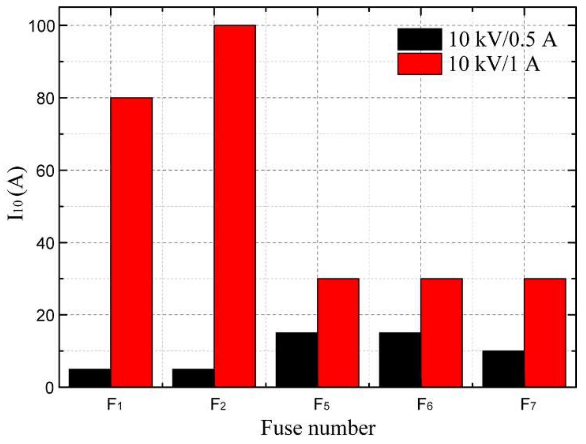
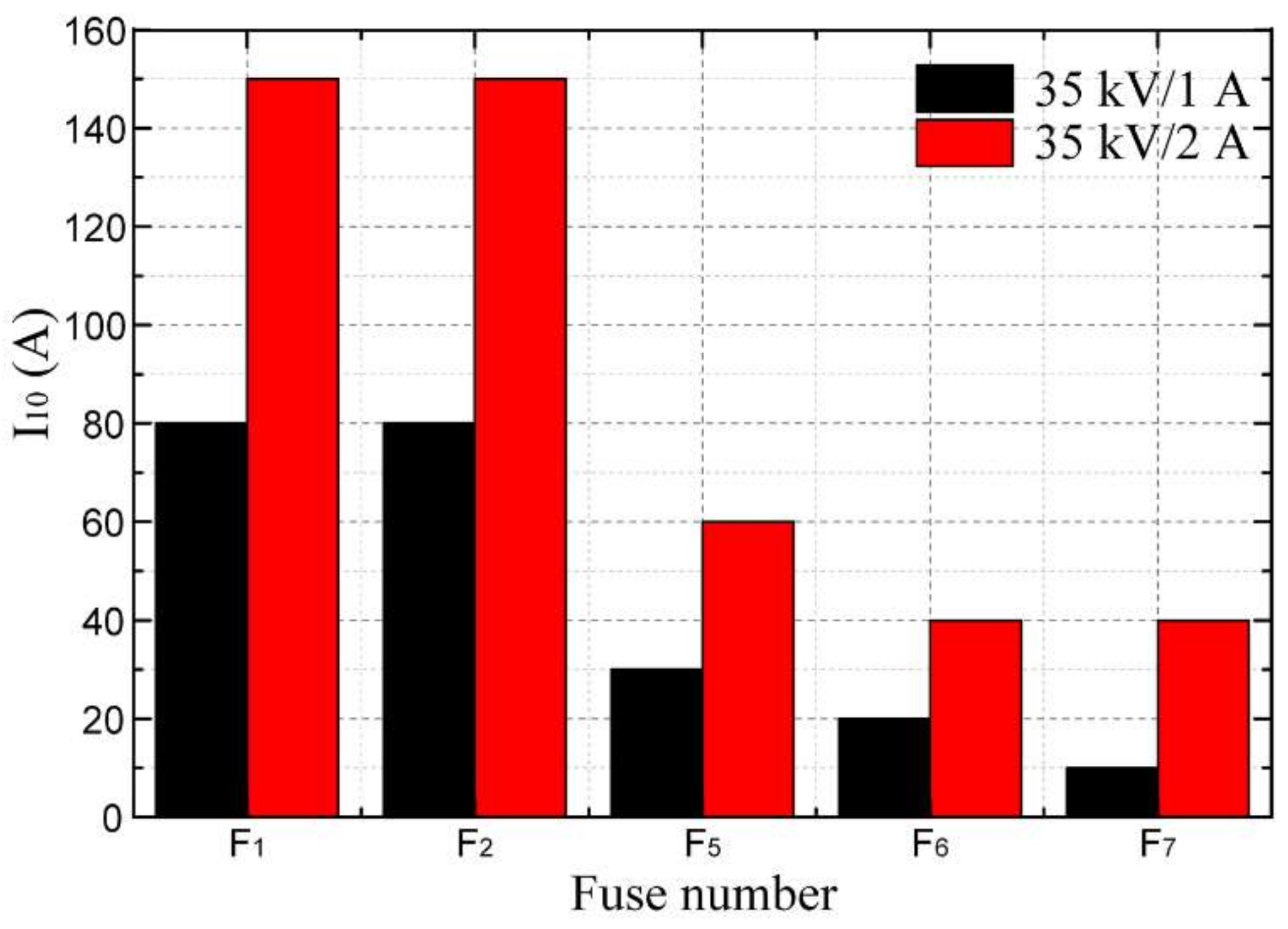
2.1. Steady Current Characteristics

In isolated neutral systems, a high voltage current limiting fuse [18,19,20] is used to protect a VT. Under normal operation, the fuse blows in time to cut off the VT when the VT current is excessively large. There are many reasons for an excessive VT current, such as ferromagnetic resonance overvoltage, short circuit faults, a capacitor discharge impulse current after fault recovery, or low fuse quality.
In actual operation, the VT fuse can blow when the breaker is open or closed. However, the fuse might also fail to blow in time, owing to ferromagnetic resonance or a short circuit fault. Therefore, the appropriate type of VT fuse must be selected based on the actual line system parameters. At present, the rated currents of VT fuses for 10 kV systems are generally 0.5 or 1 A and 1 or 2 A for 35 kV systems.
Of the fuses used in present substations, the paper considered seven VT fuse samples (F1, F2, F3, F4, F5, F6, F7) of four systems, namely 10 kV/0.5 A, 10 kV/1 A, 35 kV/1 A, and 35 kV/2 A, for steady-state current testing. This paper aimed to provide a reference for selecting VT fuses with appropriate parameters. The fuse length and cross-sectional area of the same models of the seven VT fuse samples were almost the same. The selected fuse numbers are shown in Table 1. The fuses of the four systems (10 kV/0.5 A, 10 kV/1 A, 35 kV/1 A, and 35 kV/2 A) of the same number in Table 1 were composed of the same material.
Figure 2 is a testing flow chart. The testing involved applying an alternating current, which was the current RMS (Root Mean Square) value, for 2 minutes to detect the current level at which the fuse was blown. A constant current greater than the rated current of the fuse was applied. If the current applied continuously over 2 minutes of operation did not cause a blow out, the fuse was cooled to normal temperature, disconnected, and then a current with a 0.5 A increment was applied to the fuse. This testing was continued until the fuse blew. The 2-min steady-state current values for the different systems of fuses are shown in Figure 3.
For the 10 kV/0.5 A VT fuses, the 2-min steady-state current values were in the range of 1.5–2 A which is 3–4 times the rated current; for 10 kV/1 A VT fuses, the 2-min steady-state current value showed a greater dispersion, with a minimum of 2.5 A and a maximum of 5 A. For the 35 kV VT fuses, which had a rated current of 1 A, the current values were in the range of 2.5–5 A. Fuses with a rated current of 2 A had the greatest dispersion of blow out current values, F4, F5, F6, and F7, which were maintained at approximately 5 A, and F1, F2, and F3, which were as high as 8.5, 9.5, and 11 A.
From Figure 3 and above, the 2-min steady-state current values of the different types of fuses were related only to the VT rated current, regardless of the voltage level. For fuses of the same type, the 2-min steady-state current values, based on Cu components, were higher than those based on Ag and Ni. The difference in the 2-min steady-state current values of the fuses with higher rated currents indicated that the manufacturing quality of this type of fuse varies considerably.
To match the selection of VT fuses, the paper used PSCAD (Power Systems Computer Aided Design) to construct the VT current simulation circuit, as shown in Figure 4, according to actual data from a 35 kV substation to study the magnitude of the VT current when ferromagnetic resonance occurs. The total capacitance current of the 35 kV I section bus and line was about 11 A, and the three-section branch were 17.394 km, 27.607 km and 5 km, respectively. The capacitance current of the 35 kV overhead line was 0.13 A per kilometer, and the total linear current of the three sections was about 5.55 A. This paper simulated the ferromagnetic resonance generated after cutting off the no-load line. Therefore, only the capacitance of the busbar equipment and the substation cable participate in the resonance. Therefore, the 35 kV I section busbar equipment and cable capacitance current was about 5.45 A, and the capacitance of each phase line-to-ground was calculated to be 0.286 µF. A value of 0.1 Ω was obtained by the system impedance. The secondary side bus voltage of the transformer was 35 kV. In order to accurately simulate the VT current, no lightning arrester is installed. The ferromagnetic resonance is triggered by the C phase grounding.
Figure 5 shows the simulated waveform of the ferromagnetic resonance. At 0.1 s, the C phase was grounded for 0.1 s. At 0.2 s, the grounding disappeared and a stable crossover resonance was excited. During the simulated ground fault, the peak value of each phase overvoltage was 70.0 kV, and the peak value after stabilization was 54.2 kV. The zero-sequence voltage waveform indicates that it was a 1/2-divided resonance and at this time, the current peak of the VT primary winding was approximately 4 A.
Figure 5 shows the pulse current amplitude of the ferromagnetic resonance of the transformer caused by grounding recovery. The pulse current was several times the rated current of the fuse. The fuse could not effectively isolate the fault and caused damage to the transformer. According to simulation results of the VT current during ferromagnetic resonance, the VT current was approximately 3–5 A when ferromagnetic resonance occurred in the 35 kV system. After changing the parameters, the VT current was approximately 2–4.5 A for the 10 kV system. Therefore, the VT fuse with a high rated current might not blow in time when a ferromagnetic resonance occurs.
When installing a VT fuse in a distribution network system, the VT model should be carefully selected, and the rated current should be 1 A or below.

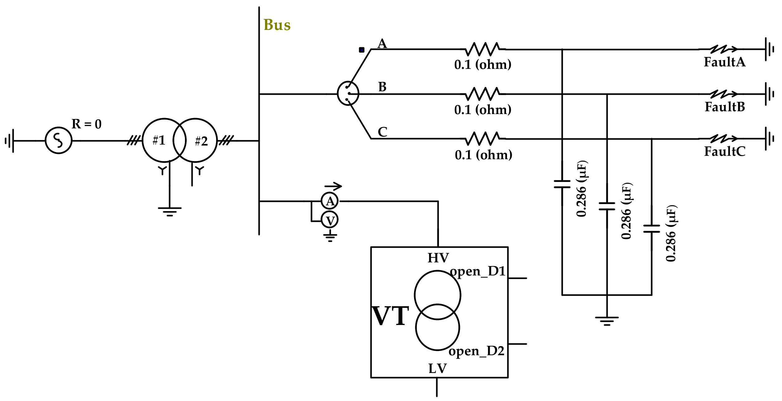
2.2. Electromagnetic Transient Impact Characteristics

When the system undergoes repeated single-phase instantaneous grounding, a larger current is induced, and the fuse might blow. This paper tested the electromagnetic transient impact resistance characteristics of the fuse, which was proposed by the author, as shown in Figure 6.
The test setup is shown in Figure 7. According to related testing of the fuse, the amplitude of the transient impulse current of the fuse that was received many times was less than 30 A, and most impacts were concentrated in the range of 5–30 A. The half-wave time of the waveform was approximately 10 ms. During the testing, the rising edge and peak value of the current were adjusted according to U, L, R, and C. According to the waveform requirements, the selected capacitor (C) was 3000 µF and the inductor (L) was 20 mH; the current amplitude was adjusted by the charging voltage and the sample resistance. This testing started from a peak current of 10 A and the impact tests were performed on five fuse samples (denoted F1, F2, F5, F6, and F7) of four systems, increasing in 5 A increments until the fuses blew. At the peak current I when the fuse was blown, the peak current was incrementally decreased from 5 A, and the fuse was repeatedly subjected to the impact test ten times to identify the impulse current I10, which the fuse could withstand ten times without blowing.
The test results of the 10 kV fuse are shown in Figure 8. Among the 10 kV/0.5 A fuses, F5, F6, and F7 withstood at least a 10 A current. The 10 kV/1 A fuses, F5, F6, and F7 withstood at least a 30 A current. The impulse current threshold values for the F1 and F2 1 A fuses were as high as 80 and 100 A, respectively. Thus, if the F1 and F2 1 A fuses were used in a distribution network, the capacitor discharge impulse current after fault recovery might not cause the fuse to blow. Power systems often have an impulse current of approximately 10 A. If the F1 and F2 0.5 A fuses were used, these fuses could not withstand a certain amplitude of transient pulse current and the fuses might blow. Therefore, for 10 kV systems a fuse should be selected with a rated current of 1 A.
The test results for the 35 kV fuse are shown in Figure 9 above. The limitation of the rated voltage of the capacitor and the high DC resistance of the individual 35 kV fuse mean that the magnitude of the impulse current that the 35 kV fuse can bear was not the limiting value. Thus, if the F1 and F2 2 A fuses were used in the 35 kV system, the fuses were not blown out easily. This might affect the operation of the power system and cause further expansion of the VT damage event.
According to analysis of the 2-min steady-state current characteristics and electromagnetic transient impact characteristics of the 10 and 35 kV fuses, a fuse might blow out abnormally if the rated current is too high or too low. Thus, this paper recommended the use of a 10 kV/1 A fuse in the 10 kV system and a 35 kV/1 A fuse in the 35 kV system.

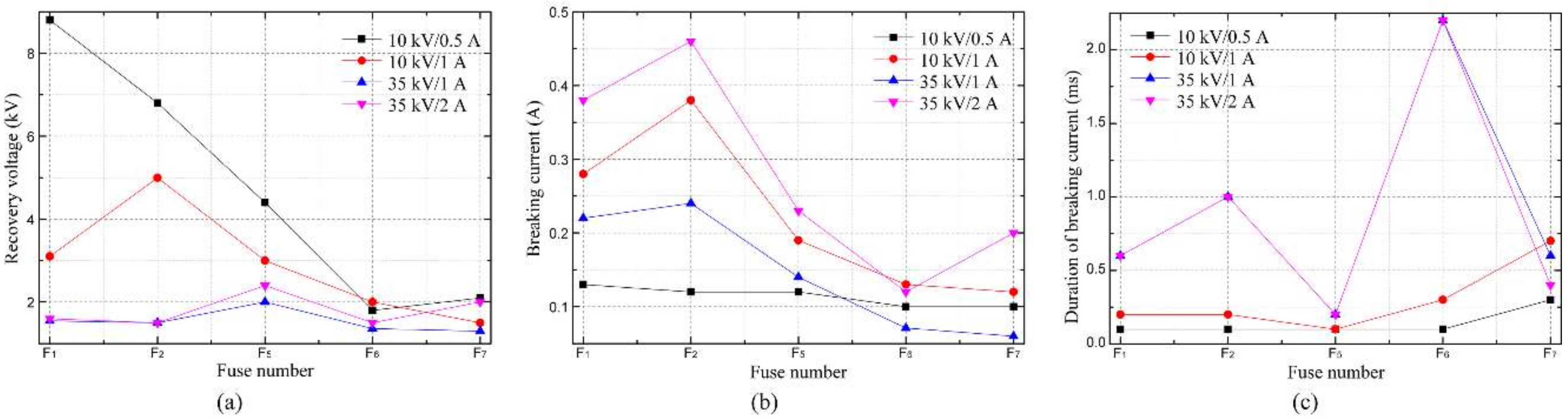
3. Breaking Characteristics

In this paper, the breaking test was used to test the arc characteristics of the VT fuse when it was broken. The test principle is illustrated in Figure 10. The charging capacitor (C) had a size of 55.7 mF and the inductance of the reactor was 186.7 mH. When a current source was applied with zero-load resistance or the resistance was small, as for the underdamped condition, the expected discharge current was 10 A for every 1 kV charging voltage applied and the frequency was 50 Hz.
The typical breaking recovery voltage and breaking current of a 35 kV/1 A fuse are shown in Figure 11. From the waveform, the recovery voltage and the breaking current had a transient pulse when the switch was closed. This was related to the internal circuit of the current source. This paper only considered the characteristics of the recovery voltage and the breaking current waveform after the pulse.
Test results of each of the five fuses from the four models, the recovered voltage and the breaking current amplitude, and the breaking current duration are shown in Figure 12. After the recovery voltage of the 35 kV fuse reached the maximum value, it dropped to the charging voltage value, and the recovery voltage was approximately 2 kV. After the recovery voltage, the 10 kV fuse reached its maximum value and suddenly changed from negative to positive, before returning to the normal charging voltage. The recovery current of the 10 kV fuse was 2–9 kV, and the breaking current was approximately 100 A. As shown in Figure 10, the fuse recovery voltage and breaking current were smaller and the performance was relatively stable for the fuses, which included Ag and Ni as the main components.
In addition, the voltage waveform of the individual type fuses fluctuated abnormally before the breaking current reached zero, owing to reignition after the fuse was blown.
A partially blown fuse is shown in Figure 13. For the 35 kV fuse, the F5 fuse wire disappeared, and the other fuses featured multiple fuses in the middle of the fuse wire. For 10 kV fuses, the fusing characteristics of each fuse were different. In Figure 13, the fuse tube had not exploded, and it was found that the melt breaking performance was inconsistent under the same breaking current, which affected the performance of the fuse isolation fault.

4. X-Ray Examination

Owing to the closed structure of the fuse, this paper used X-ray inspection technology to check the internal structure of fuse. The X-ray detector is shown in Figure 14. The fuse X-ray test charts of 35 kV/2 A fuses are shown in Figure 15.
These results showed that individual fuses were unqualified. F1, F2, F3, and F4 fuses had no bracket for the fuse to be wound, as shown in Figure 15a–d. Some fuses were not evenly wound and lay close to the internal tube wall of the fuse, which might have caused the fuse to heat unevenly, leading to local heating or blackening under large currents. These features might have also affected the current limiting characteristics of the fuse. The F4 fuse showed oxidation phenomenon, which caused the resistance of the fuse to increase and heating to intensify, such that the fuse was more likely to blow out under normal conditions. In addition, F1 and F3 used two 1 A fuses in parallel, which made it less easy for the fuse to melt when the current was overloaded. This resulted in the maximum 2-min steady-state current value being much higher than the value for other fuses of the same type.
The F5, F6, and F7 fuses had winding brackets, as shown in Figure 15e–g, which promoted relatively stable performance of the fuses and gave better reliability in the 2-min steady-state current and electromagnetic transient impact tests. If the fuse had no bracket, fuse oxidation, fusing in parallel and other quality problems made it easy for the fuse to blow out abnormally. Therefore, it is advisable to select a fuse, which has a single fuse and a winding bracket, which is not easily oxidized.

5. Corona Characteristics

The experimental setup is shown in Figure 16. The corona test scheme was used to break the fuse tube wall, so that the internal fuse was exposed to air and the corona characteristics of the fuse were observed by an ultraviolet imager under different voltages [21,22,23]. The epoxy support plate had a size of 100 mm × 400 mm × 4000 mm. The bottom of the epoxy board included a grounding plate. The 100 mm tube wall in the middle of the fuse was broken and the fuse was not broken in air. The ultraviolet imager was placed 2 m away from the fuse and ensured that the exposed fuses were equal in length in the same view of field of the ultraviolet imager. The ultraviolet imager gain was set to be 100 for all experiments (ultraviolet filtering filters out 100% of the sun’s light), the photon counting mode performed photon counting in a specified area.
During the test, voltages of 10, 20, and 30 kV were applied to the ends of the fuses. This paper observed luminescence of the fuse coils and the number of photons from corona luminescence was measured. Figure 17 shows a corona ultraviolet image of the fuse.
Figure 18 shows a graph of the photons from corona luminescence of a fuse when voltages of 10, 20, and 30 kV were applied to the ends of the fuse, respectively. These results showed that the corona luminescence of the 1 A fuse was weaker than that of 2 A fuse, and the corona luminescence results of each fuse at the same voltage were different. This was because the main components of the fuse were different and the individual fuses had different oxidation conditions. Fuses based on a main component of Ag or Ni were less prone to show corona and fuses based on Cu were more susceptible to corona effects. In addition, because the F1 and F2 fuses did not have a winding bracket, the fuse exposed to the air might have vibrated when a voltage was applied. Therefore, a fuse with a melt body composed of Cu should be avoided, and fuses based on Ag or Ni should be preferred.

6. Conclusions

This paper provides guidance for selecting VT fuses based on various test analyses of VT fuse performance. The 2-min steady-state current characteristic of the fuse for an electromagnetic voltage transformer indicated that the steady-state current was too large, and the transformer could not be effectively isolated. The electromagnetic transient characteristics indicated that the steady-state current was too small, and the fuse was prone to blow frequently caused by electromagnetic transient processes. Melt corona discharge also affected fuse life. The selected fuse should be tested for 2-min steady-state current characteristic, melt corona discharge level, and electromagnetic transient impact characteristics. The fuse selection methods are as follows: The 35 and 10 kV systems should use fuses with a rated current of 1 A when the VT fuse of the distribution network system is selected. It is advisable to select a fuse that has a single fuse, a winding bracket and one that is not easily oxidized. Fuses composed of a Cu melt body should be avoided, and those based on Ag or Ni should be preferred.

Author Contributions

Conceptualization, H.L., K.W. and Q.Y.; Methodology, H.L., K.W. and Q.Y.; Validation, H.L. and L.Y.; Formal Analysis, H.L., K.W. and Q.Y.; Investigation, H.L., L.Y. and J.H.; Data Curation, H.L.; Writing—Original Draft Preparation, L.Y.; Writing—Review & Editing, Q.Y.; Funding Acquisition, K.W.

Funding

This research was funded by Yunnan electric power corporation of China (YNKJXM20170214; YNKJ00000045).

Conflicts of Interest

The authors declare no conflict of interest. The funders had no role in the design of the study; in the collection, analyses, or interpretation of data; in the writing of the manuscript, or in the decision to publish the results.

References

  1. Xie, Y.-X.; Wang, J.-M. Review of high voltage full range fuses. High Volt. Appar. 1987, 4, 50–55. [Google Scholar]
  2. Tanggawelu, B.; Mukerjee, R.N.; Ariffin, A.E. Ferroresonance studies in malaysian utility’s distribution network. In Proceedings of the 2003 IEEE Power Engineering Society General Meeting (IEEE Cat. No.03CH37491), Toronto, ON, Canada, 13–17 July 2003; pp. 125–128. [Google Scholar]
  3. Clarke, E.; Peterson, H.A.; Light, P.H. Abnormal Voltage Conditions in Three-Phase Systems Produced by Single-Phase Switching. Electr. Eng. 1941, 60, 329–339. [Google Scholar] [CrossRef]
  4. Iravani, M.R.; Chaudhary, A.K.S. Modeling and analysis guidelines for slow transients-part: The study of ferroresonance. IEEE Trans. Power Deliv. 2000, 15, 255–265. [Google Scholar] [CrossRef]
  5. Mork, B.A.; Stuehm, D.L. Application of nonlinear dynamics and chaos to ferroresonance in distribution systems. IEEE Trans. Power Deliv. 1994, 9, 1009–1017. [Google Scholar] [CrossRef]
  6. Li, Y.; Shi, W.; Qin, R. A systematical method for suppressing ferroresonance at neutral-grounded substations. IEEE Trans. Power Deliv. 2003, 18, 1009–1014. [Google Scholar] [CrossRef]
  7. Emin, Z.; Al Zahawi, B.A.T.; Auckland, D.W. Ferroresonance in electromagnetic voltage transformers: A study based on nonlinear dynamics. IEE Proc. Gener. Transm. Distrib. 1997, 144, 383–387. [Google Scholar] [CrossRef]
  8. Chakravarthy, S.K.; Nayar, C.V. Series ferroresonance in power systems. Int. J. Electr. Power Energy Syst. 1995, 17, 267–274. [Google Scholar] [CrossRef]
  9. Walling, R.A. Ferroresonance in low-loss distribution transformers. In Proceedings of the Power Engineering Society General Meeting, IEEE, 2003, Toronto, ON, Canada, 13–17 July 2003. [Google Scholar]
  10. Radmanesh, H.; Gharehpetian, G.B. Ferroresonance suppression in power transformers using chaos theory. Int. J. Electr. Power Energy Syst. 2013, 45, 1–9. [Google Scholar] [CrossRef]
  11. Nattapan, T.; Boonyang, P.; Hideaki, O. Analysis of Ferroresonance Phenomenon in 22 kV Distribution System with a Photovoltaic Source by PSCAD/EMTDC. Energies 2018, 11, 1742. [Google Scholar]
  12. Lin, C.; Qing, Y.; Jing, W.; Wenxia, S.M. Classification of Fundamental Ferroresonance, Single Phase-to-Ground and Wire Breakage Over-Voltages in Isolated Neutral Networks. Energies 2011, 4, 1301–1320. [Google Scholar] [Green Version]
  13. Wang, M.-Q.; Chen, W.-J.; Li, Y.-J. A countermeasure to deal with abnormal fusing of high voltage fuse for potential transformer in 35 kV oilfield power distribution system. Power Syst. Technol. 2012, 36, 283–288. [Google Scholar]
  14. Liang, Z.-R.; Zhao, M.-Y.; Niu, S.-S.; Liu, H.-S.; Liang, S.; Guo, Y.-C. Study on Defects and New Measures of Control Measures for Fuse Fuse of Voltage Transformer in Distribution Network. Electr. Power Autom. Equip. 2016, 36, 17–24. [Google Scholar]
  15. Zhou, X.-M.; Yang, Y.-H.; Tan, W.-P. Analysis of Causes of Fuse of PT High Voltage Fuse in Distribution System. Mod. Electr. Power. 2007, 24, 34–37. [Google Scholar]
  16. Adrian, P. Temperature Distribution of HBC Fuses with Asymmetric Electric Current Ratios through Fuselinks. Energies 2018, 11, 1990. [Google Scholar]
  17. Zhou, T.; Wen, Y.-F.; Mao, L.-M.; Liu, X.-F. High-voltage current-limiting fuse with EMTP/ATP. High Volt. Eng. 2007, 10, 37–40. [Google Scholar]
  18. Wu, A.Y.; Yin, Y. Fault-current limiter applications in medium and high-voltage power distribution systems. IEEE Trans. Ind. Appl. 1998, 34, 236–242. [Google Scholar] [CrossRef]
  19. Fortin, M. Characteristics of High-Voltage Current-Limiting Fuses for Distribution Systems. IEEE Trans. Power Appar. Syst. 1982, PAS-101, 2056–2060. [Google Scholar] [CrossRef]
  20. Wang, H.; Li, H.; Tao, G. Research and Application of 10kV Built-in High Voltage Protection Distribution Transformer. In Proceedings of the 2018 China International Conference on Electricity Distribution (CICED), Tianjin, China, 17–19 September 2018; pp. 280–284. [Google Scholar]
  21. Zhou, W.; Li, H.; Yi, X.; Tu, J.; Yu, J. A Criterion for UV Detection of AC Corona Inception in a Rod-plane Air Gap. IEEE Trans. Dielectr. Electr. Insul. 2011, 18, 232–237. [Google Scholar] [CrossRef]
  22. Wang, S.; Lv, F.; Liu, Y. Estimation of discharge magnitude of composite insulator surface corona discharge based on ultraviolet imaging method. IEEE Trans. Dielectr. Electr. Insul. 2014, 21, 1697–1704. [Google Scholar] [CrossRef]
  23. Li, Z.; Li, L.; Jiang, X.; Hu, J.; Zhang, Z.; Zhang, W. Effects of Different Factors on Electrical Equipment UV Corona Discharge Detection. Energies 2016, 9, 369. [Google Scholar] [CrossRef]
Figure 1. Winding damage of voltage transformer (VT) for phase-A.
Energies 12 00737 g001
Figure 2. Flow chart for the testing.
Energies 12 00737 g002
Figure 3. The 2-min steady-state current values of the 10/35 kV VT systems.
Energies 12 00737 g003
Figure 4. Ferroresonance current simulation of 35 kV VT. HV: high voltage input; LV: low voltage output.
Energies 12 00737 g004
Figure 5. Ferromagnetic resonance waveform at 35 kV. (a) Voltage of VT; (b) current of VT.
Energies 12 00737 g005
Figure 6. Electromagnetic transient impact test circuit of fuse. C: main capacitor; S: shunt; CRO: oscilloscope; G: spark sphere gap; R, L: resistance and inductance of all components and loops of the line; D: silicon stack; r: protection resistor; T: charging transformer; O: sample.
Energies 12 00737 g006
Figure 7. The picture of the test setup.
Energies 12 00737 g007
Figure 8. Highest impulse current amplitude borne by 10 kV fuses.
Energies 12 00737 g008
Figure 9. Highest impulse current amplitude borne by 35 kV fuses.
Energies 12 00737 g009
Figure 10. Fuse breaking test schematic diagram.
Energies 12 00737 g010
Figure 11. Breaking waveform of 35 kV/1 A fuses. (a) Recovery voltage; (b) breaking current.
Energies 12 00737 g011
Figure 12. Breaking characteristic of each fuse type. (a) Amplitude of recovery voltage; (b) amplitude of breaking current; (c) duration of breaking current.
Energies 12 00737 g012
Figure 13. Blowing characteristic of fuses.
Energies 12 00737 g013
Figure 14. X-ray detector.
Energies 12 00737 g014
Figure 15. X-ray examination of fuses. (a) F1 35 kV/2 A; (b) F2 35 kV/2 A; (c) F3 35 kV/2 A; (d) F4 35 kV/2 A; (e) F5 35 kV/2 A; (f) F6 35 kV/2 A; (g) F7 35 kV/2 A.
Energies 12 00737 g015
Figure 16. Corona test schematic of fuse.
Energies 12 00737 g016
Figure 17. Corona ultraviolet image of fuse.
Energies 12 00737 g017
Figure 18. Number of photons measured for each sample of fuses. (a) 10 kV; (b) 20 kV; (c) 30 kV.
Energies 12 00737 g018
Table 1. The fuse samples.
Fuse NumberF1F2F3F4F5F6F7
Main componentCuCuCuCuAgAgNi

