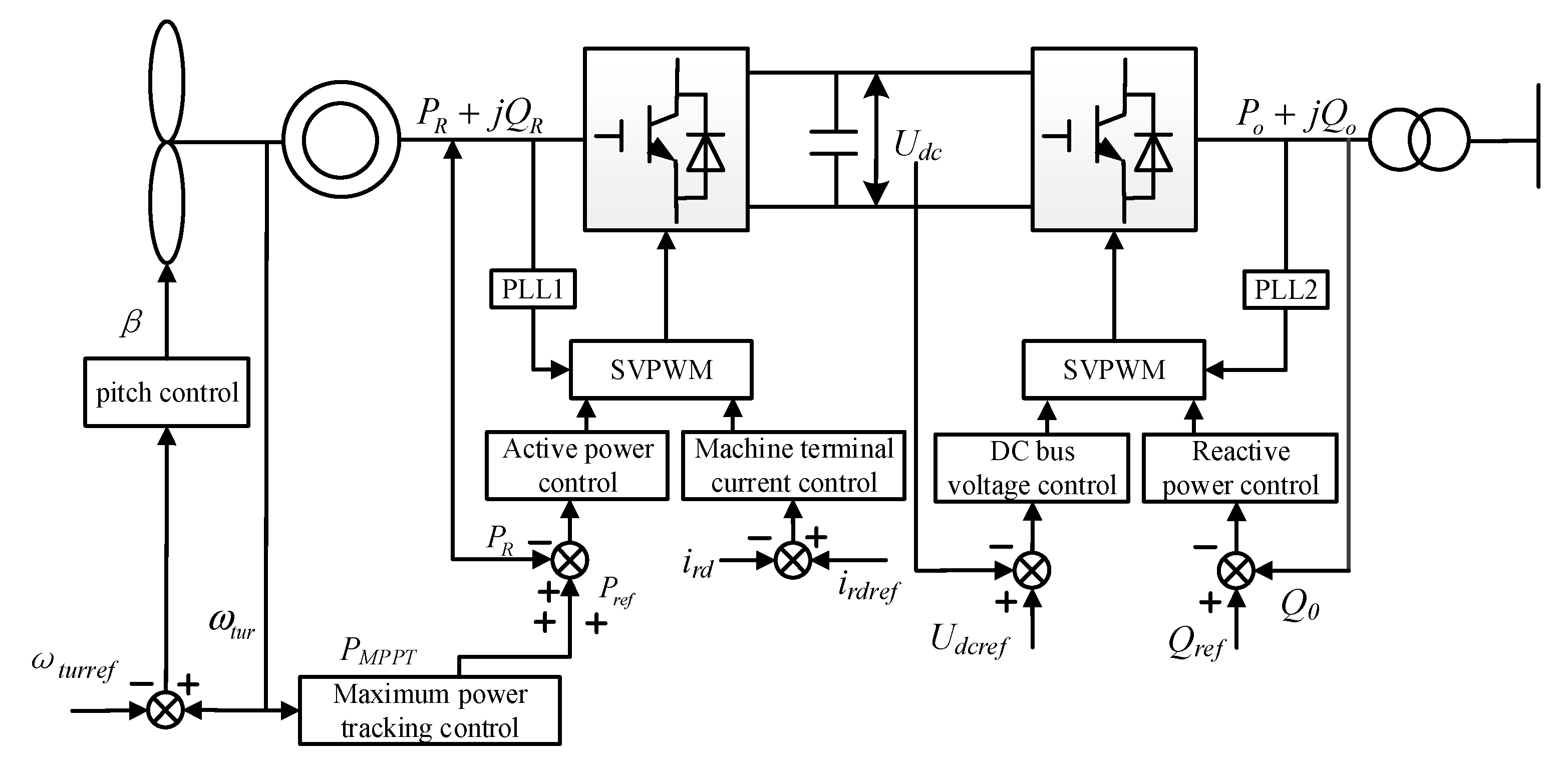
Figure 1.
A typical configuration of the permanent magnet synchronous generator (PMSG) model.
Figure 1.
A typical configuration of the permanent magnet synchronous generator (PMSG) model.
Figure 2.
Control strategy of grid-side converter.
Figure 2.
Control strategy of grid-side converter.
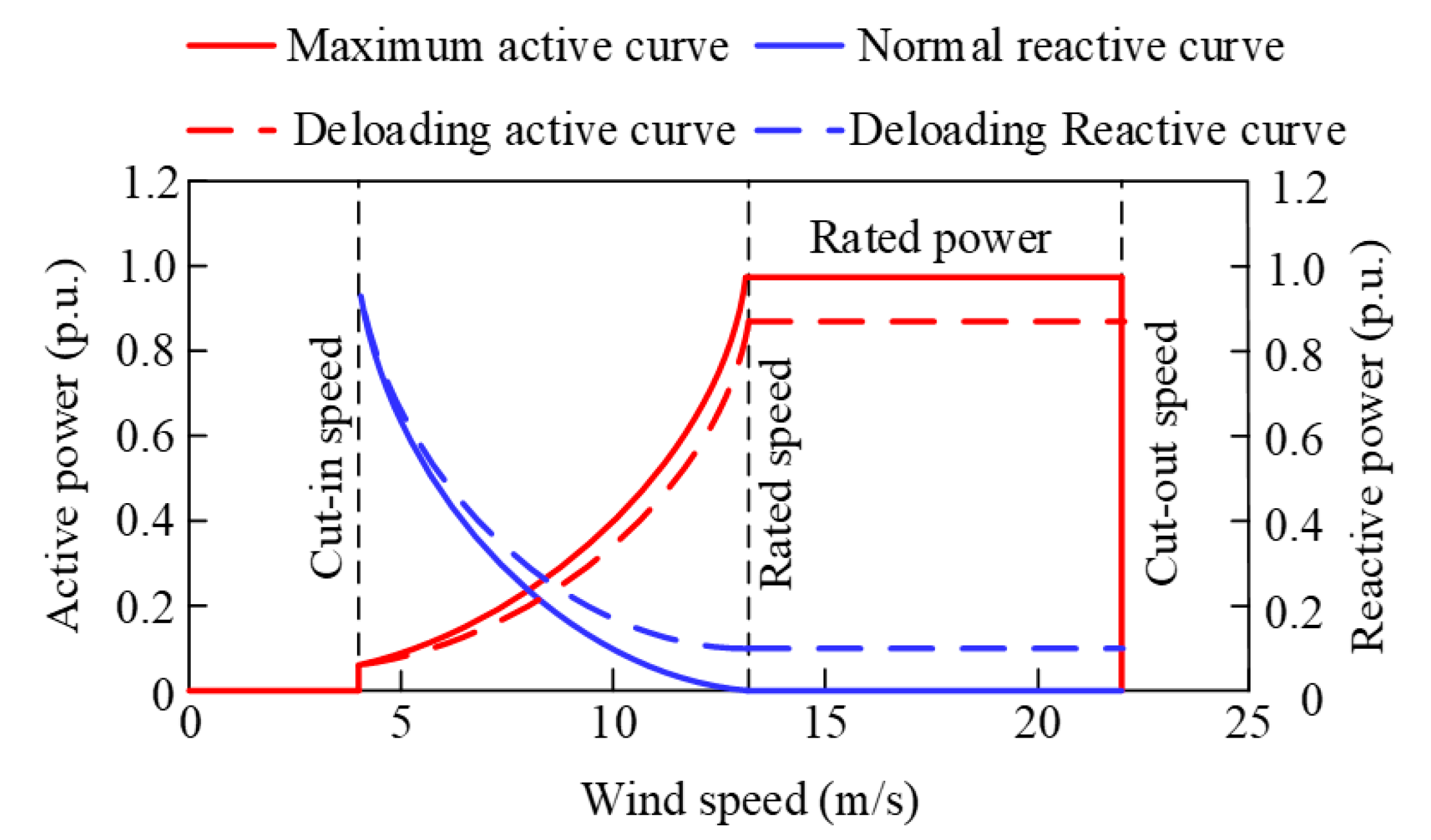
Figure 3.
Active and reactive power range of the PMSG.
Figure 3.
Active and reactive power range of the PMSG.
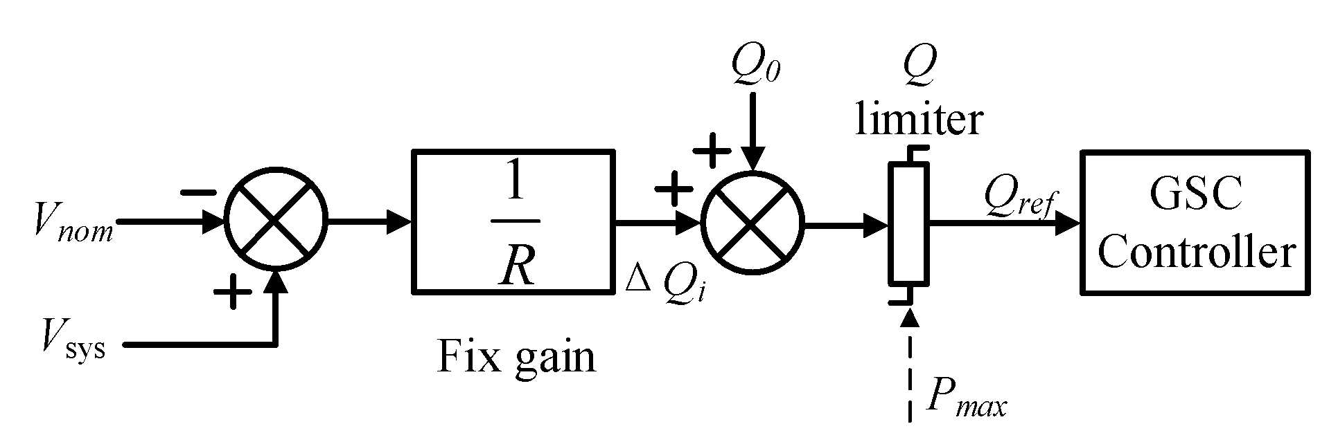
Figure 4.
Conventional fixed-gain voltage control scheme of a PMSG.
Figure 4.
Conventional fixed-gain voltage control scheme of a PMSG.
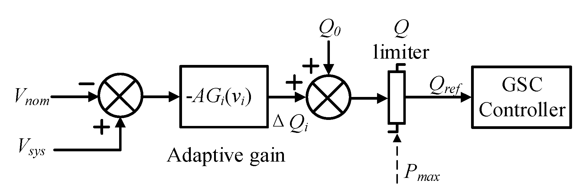
Figure 5.
Proposed adaptive-gain voltage control scheme of a PMSG.
Figure 5.
Proposed adaptive-gain voltage control scheme of a PMSG.
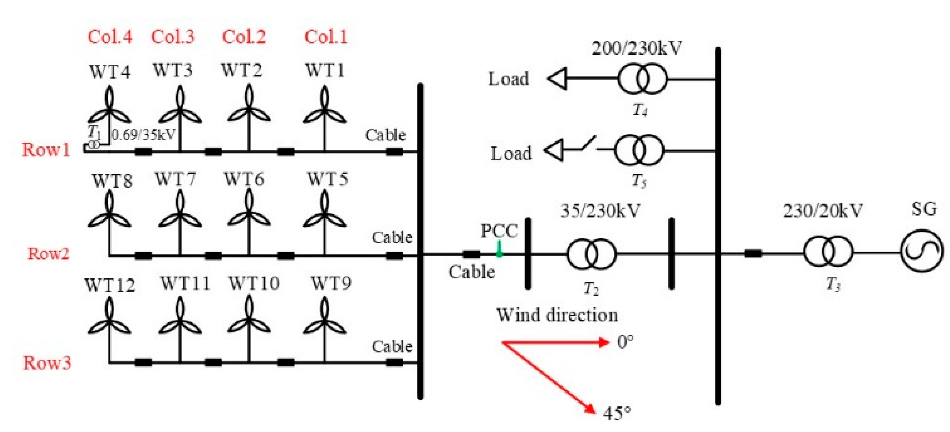
Figure 6.
Test system used in this paper.
Figure 6.
Test system used in this paper.
Figure 7.
IEEE alternator supplied rectifier excitation system model.
Figure 7.
IEEE alternator supplied rectifier excitation system model.
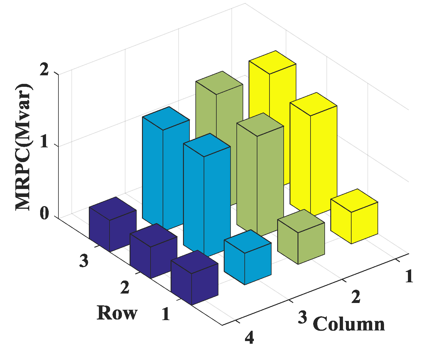
Figure 8.
Maximum reactive power capacity (MRPC) of the all PMSGs in case 1.
Figure 8.
Maximum reactive power capacity (MRPC) of the all PMSGs in case 1.
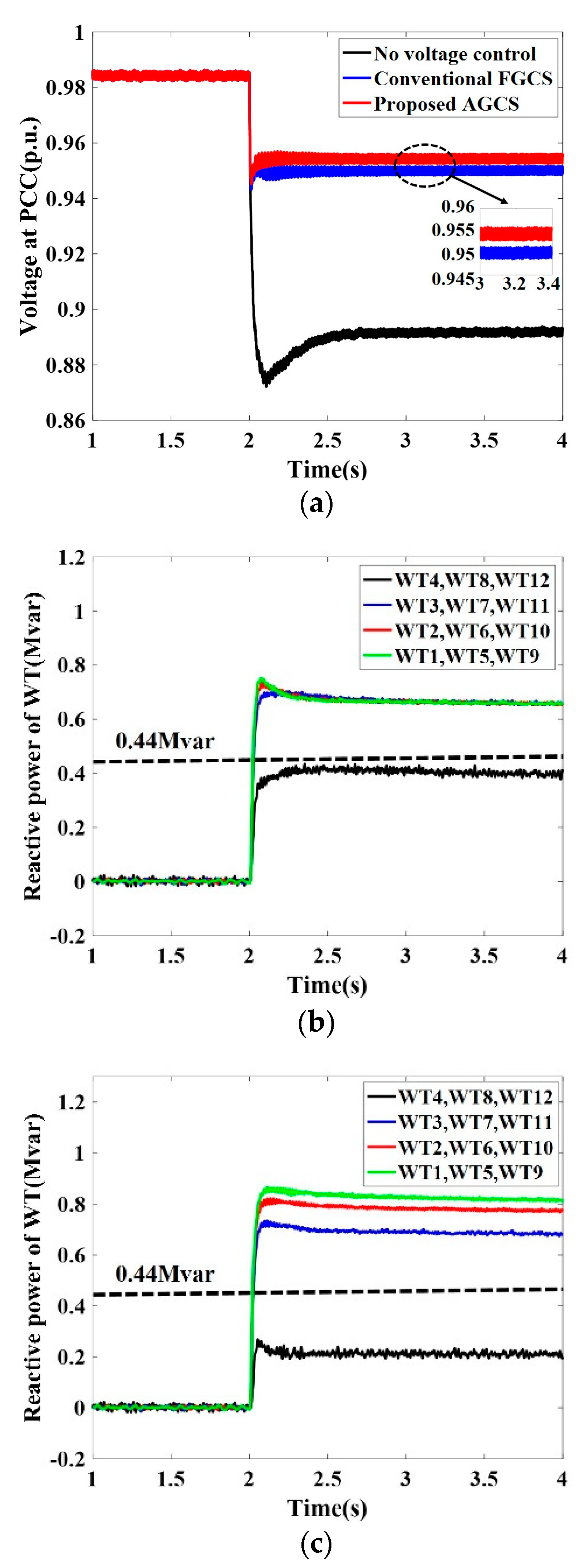
Figure 9.
Results of Case 1. (a) Voltage at PCC, (b) reactive power of PMSGs under the conventional FGCS, (c) reactive power of PMSGs under the proposed AGCS.
Figure 9.
Results of Case 1. (a) Voltage at PCC, (b) reactive power of PMSGs under the conventional FGCS, (c) reactive power of PMSGs under the proposed AGCS.
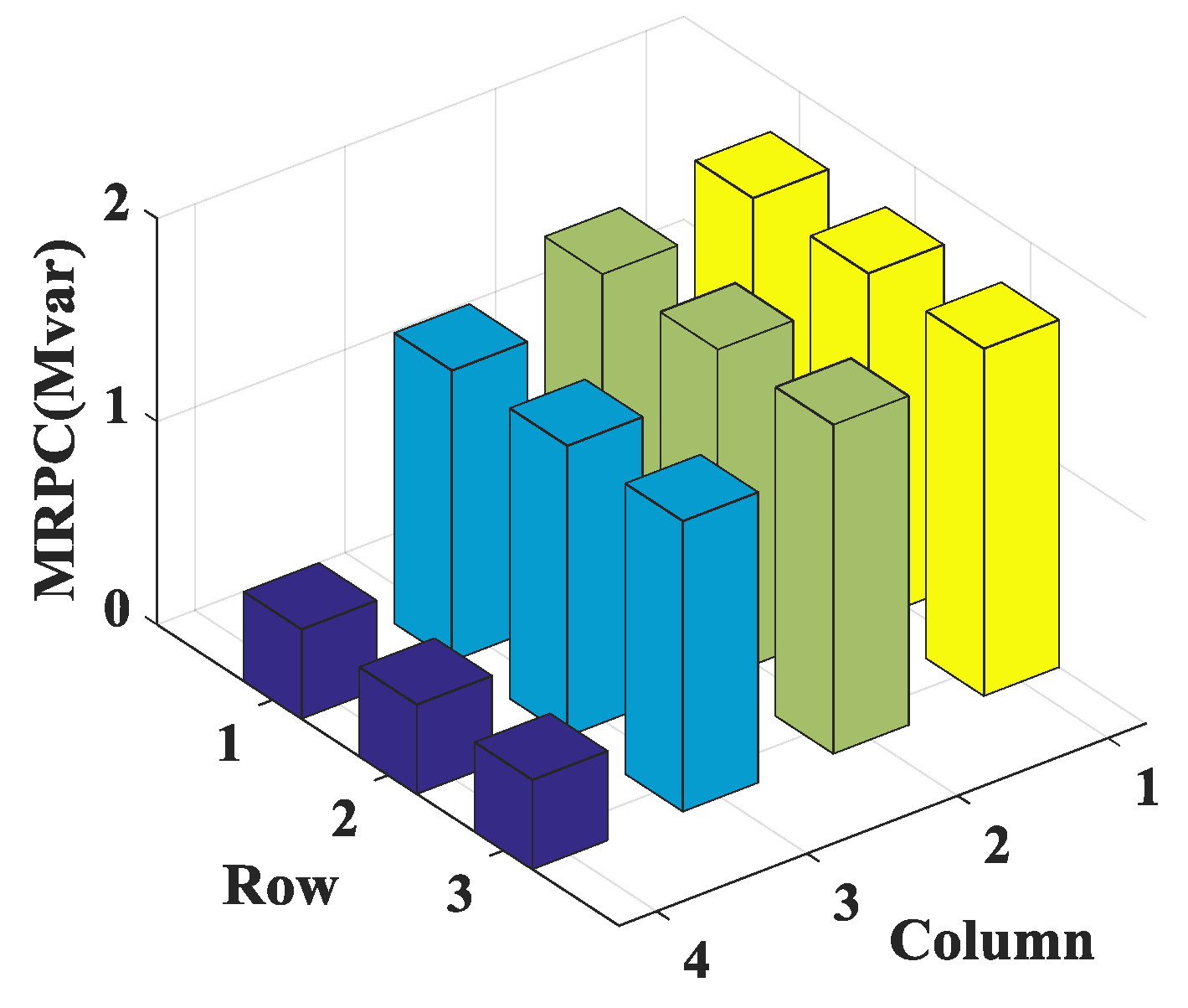
Figure 10.
MRPC of the all PMSGs in case 2.
Figure 10.
MRPC of the all PMSGs in case 2.
Figure 11.
Results of Case 2. (a) Voltage at PCC, (b) reactive power of PMSGs under the conventional FGCS, (c) reactive power of PMSGs under the proposed AGCS.
Figure 11.
Results of Case 2. (a) Voltage at PCC, (b) reactive power of PMSGs under the conventional FGCS, (c) reactive power of PMSGs under the proposed AGCS.
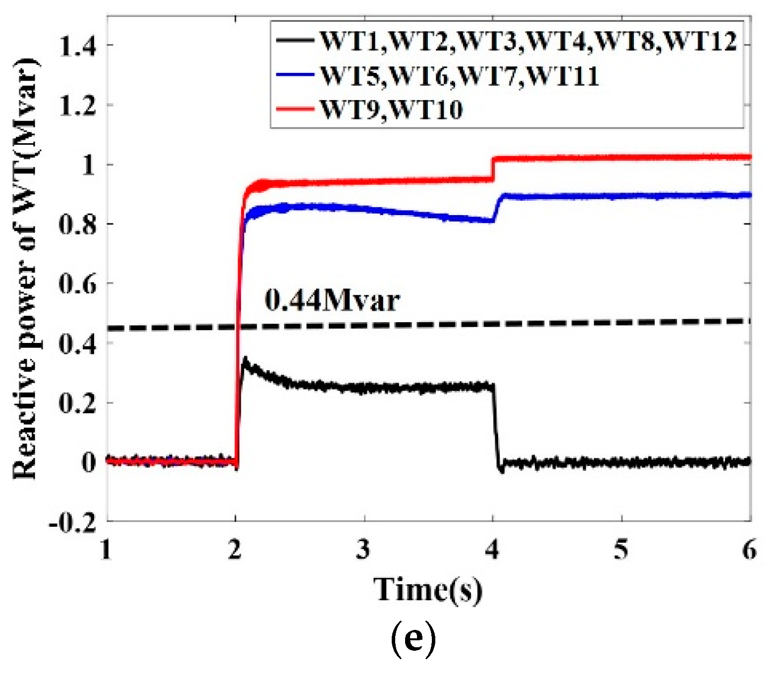
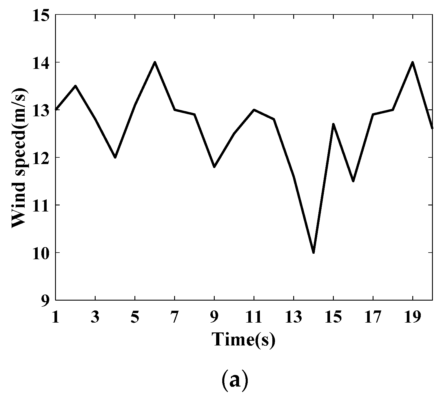
Figure 12.
Results of Case 3. (a) Wind speed, (b) voltage at PCC, (c) reactive power of PMSGs under the conventional FGCS, (d) adaptive gain of PMSGs, (e) reactive power of PMSGs under the proposed AGCS.
Figure 12.
Results of Case 3. (a) Wind speed, (b) voltage at PCC, (c) reactive power of PMSGs under the conventional FGCS, (d) adaptive gain of PMSGs, (e) reactive power of PMSGs under the proposed AGCS.
Figure 13.
Results of Case 4. (a) Wind speed, (b) voltage at PCC, (c) reactive power of PMSGs under the conventional FGCS, (d) adaptive gain of PMSGs, (e) reactive power of PMSGs under the proposed AGCS.
Figure 13.
Results of Case 4. (a) Wind speed, (b) voltage at PCC, (c) reactive power of PMSGs under the conventional FGCS, (d) adaptive gain of PMSGs, (e) reactive power of PMSGs under the proposed AGCS.
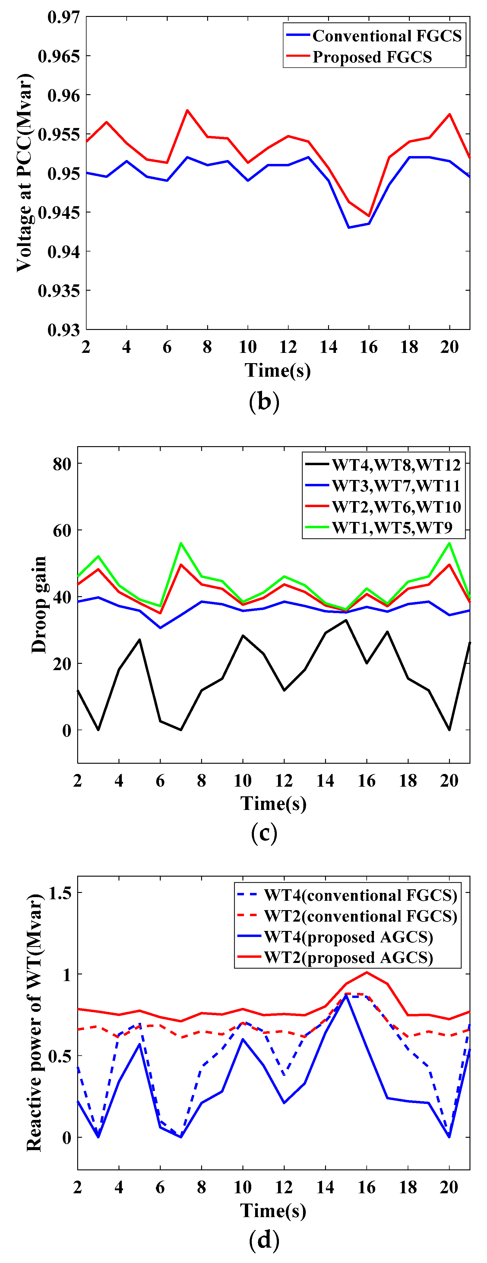
Figure 14.
Results of Case 5. (a) Real pattern of wind speed, (b) voltage at PCC, (c) adaptive gain of PMSGs, (d) reactive power of PMSGs under the proposed AGCS.
Figure 14.
Results of Case 5. (a) Real pattern of wind speed, (b) voltage at PCC, (c) adaptive gain of PMSGs, (d) reactive power of PMSGs under the proposed AGCS.
Table 1.
Parameters of a PMSG used in this paper.
Table 1.
Parameters of a PMSG used in this paper.
| Parameters | Units | Values |
|---|
| Nominal Apparent Power | MVA | 2 |
| Nominal Stator Voltage | kV | 0.69 |
| Stator Resistance | p.u. | 0.0108 |
| Stator Leakage Reactance | p.u. | 0.102 |
| Rotor Resistance | p.u. | 0.01 |
| Rotor Leakage Reactance | p.u. | 0.11 |
| Inertia Time Constant | s | 3 |
Table 2.
Coefficients of the IEEE alternator supplied rectifier excitation system model.
Table 2.
Coefficients of the IEEE alternator supplied rectifier excitation system model.
| TC | TB | KA | TA | KF | TF | TE | SE | KD |
|---|
| 0 | 0 | 400 | 0.02 | 0.03 | 1 | 0.8 | 4.18 | 0.38 |
Table 3.
Wind speed of Case 1 (m/s).
Table 3.
Wind speed of Case 1 (m/s).
| Col.1 | Col.2 | Col.3 | Col.4 |
|---|
| 13 | 13 | 13 | 13 |
| 13 | 11.68 | 11.68 | 11.68 |
| 13 | 11.68 | 10.97 | 10.97 |
Table 4.
MRPC of Case 1 (Mvar).
Table 4.
MRPC of Case 1 (Mvar).
| Col.1 | Col.2 | Col.3 | Col.4 |
|---|
| 0.44 | 0.44 | 0.44 | 0.44 |
| 0.44 | 1.41 | 1.41 | 1.41 |
| 0.44 | 1.41 | 1.62 | 1.62 |
Table 5.
Droop gain of Case 1.
Table 5.
Droop gain of Case 1.
| Col.1 | Col.2 | Col.3 | Col.4 |
|---|
| 16.04 | 16.04 | 16.04 | 16.04 |
| 16.04 | 51.40 | 51.40 | 51.40 |
| 16.04 | 51.40 | 59.07 | 59.07 |
Table 6.
Wind speed of case 2 (m/s).
Table 6.
Wind speed of case 2 (m/s).
| Col.1 | Col.2 | Col.3 | Col.4 |
|---|
| 13 | 11.61 | 10.93 | 10.48 |
| 13 | 11.61 | 10.93 | 10.48 |
| 13 | 11.61 | 10.93 | 10.48 |
Table 7.
MRPC of Case 2 (Mvar).
Table 7.
MRPC of Case 2 (Mvar).
| Col.1 | Col.2 | Col.3 | Col.4 |
|---|
| 0.44 | 1.43 | 1.62 | 1.71 |
| 0.44 | 1.43 | 1.62 | 1.71 |
| 0.44 | 1.43 | 1.62 | 1.71 |
Table 8.
Droop gain of case 2.
Table 8.
Droop gain of case 2.
| Col.1 | Col.2 | Col.3 | Col.4 |
|---|
| 11.85 | 38.5 | 43.62 | 46.04 |
| 11.85 | 38.5 | 43.62 | 46.04 |
| 11.85 | 38.5 | 43.62 | 46.04 |
Table 9.
Wind speed of Case 3 (m/s).
Table 9.
Wind speed of Case 3 (m/s).
| Col.1 | Col.2 | Col.3 | Col.4 |
|---|
| 13→14 | 13→14 | 13→14 | 13→14 |
| 13→14 | 11.68 | 11.68 | 11.68 |
| 13→14 | 11.68 | 10.97 | 10.97 |
Table 10.
MRPC of Case 3 (Mvar).
Table 10.
MRPC of Case 3 (Mvar).
| Col.1 | Col.2 | Col.3 | Col.4 |
|---|
| 0.44→0 | 0.44→0 | 0.44→0 | 0.44→0 |
| 0.44→0 | 1.41 | 1.41 | 1.41 |
| 0.44→0 | 1.41 | 1.62 | 1.62 |
Table 11.
Droop gain of Case 3.
Table 11.
Droop gain of Case 3.
| Col.1 | Col.2 | Col.3 | Col.4 |
|---|
| 16.04→0 | 16.04→0 | 16.04→0 | 16.04→0 |
| 16.04→0 | 51.40→66.68 | 51.40→66.68 | 51.40→66.68 |
| 16.04→0 | 51.40→66.68 | 59.07→76.42 | 59.07→76.42 |
Table 12.
Wind speed of Case 3 (m/s).
Table 12.
Wind speed of Case 3 (m/s).
| Col.1 | Col.2 | Col.3 | Col.4 |
|---|
| 13→14 | 11.61 | 10.93 | 10.48 |
| 13→14 | 11.61 | 10.93 | 10.48 |
| 13→14 | 11.61 | 10.93 | 10.48 |
Table 13.
MRPC of Case 3 (Mvar).
Table 13.
MRPC of Case 3 (Mvar).
| Col.1 | Col.2 | Col.3 | Col.4 |
|---|
| 0.44→0 | 1.43 | 1.62 | 1.71 |
| 0.44→0 | 1.43 | 1.62 | 1.71 |
| 0.44→0 | 1.43 | 1.62 | 1.71 |
Table 14.
Droop gain of Case 3.
Table 14.
Droop gain of Case 3.
| Col.1 | Col.2 | Col.3 | Col.4 |
|---|
| 11.85→0 | 38.5→42.06 | 43.62→47.65 | 46.04→50.29 |
| 11.85→0 | 38.5→42.06 | 43.62→47.65 | 46.04→50.29 |
| 11.85→0 | 38.5→42.06 | 43.62→47.65 | 46.04→50.29 |


