Abstract
The parallel system is a kind of scientific research method based on an artificial system and computational experiments, which can not only reflect the dynamic process of the real system but also optimize its control process in real time. Given the rapid development of wind energy technology, how to shorten the development and deployment cycle and decrease the programming difficulties of wind energy conversion system (WECS) are major issues for improving the utilization of this form of energy. In this paper, the Data Engine is used as a computing environment to form a parallel WECS for studying the engineering application of WECS. With the support of the programming methods of graphical component configurations, visualization technology and dynamic reconfiguration technology, a maximum power point tracking (MPPT) computing experiment of the parallel WECS is carried out. After comparing with MATLAB simulation results, the parallel WECS is verified as having good performance. The Data Engine is an ideal computing unit for modeling and computation of the parallel system and can establish a parallel relationship between the artificial system and the real system so as to achieve the optimal control of WECS.
1. Introduction
Wind energy is one of the most promising renewable energy resources for generating electricity due to its cost competitiveness compared with other conventional energy resources. Industrial control enterprises around the world are devoting great effort to developing and utilizing wind energy [1]. Research into wind energy has also significantly increased [2]. As a result, how to improve the efficiency of wind energy conversion has become an important scientific problem which has drawn great attention from academia [3].
At present, in order to improve the conversion efficiency of wind energy, the corresponding system architectures of wind energy conversion are put forward and the relevant simulating analysis or physical research to obtain the maximum power of wind energy is carried out [4,5,6]. Nevertheless, the cost of their design, development and maintenance are extremely high which largely weaken the benefits of the algorithm research of the automation system to some extent. The reason is that the engineering application of the wind energy conversion control algorithm is a complex cross-disciplinary subject involving mathematics, control, management and computer technology and the complexity of the current automation system management, which cannot be significantly reduced by traditional computing platforms. Thus, a more scientific architecture and an efficient algorithmic implementation platform has become an urgent demand for the wind energy conversion system (WECS) application. Parallel system theory provides an effective method for this.
The parallel system refers to a common system which consists of a physical reality system and one or more virtual/ideal artificial systems [7]. In a common system, the artificial systems are considered to be other possible implementation methods of actual systems, which can intervene in the management and control of the real system more actively and dynamically, so as to reduce the difficulty of the complex system research and improve the system control efficiency [8,9]. It must be pointed out that continuously reducing the complexity of system structure and improving the control quality of a wind energy generation system is not only the research goal, but also the trend in this technology [10]. The former mainly relies on the distributed computing [11], and the latter depends on the virtual–actual interaction technique.
In order to establish the parallel system and verify the efficiency of the control algorithm, most researchers establish artificial systems on a third-party simulation platform to simulate and test the control algorithm, then converting it to a specific program recognized by the actual controller or directly applying the simulation software to an actual control system through the communication protocol. These approaches will lead to low efficiency in the parallel system, besides, the simulation software cannot guarantee the stability and robustness of the control system. Considering the factors such as generality, modularity and visualization, this paper aims to change the traditional software engineering and computing environment, and propose a new computing environment based on the parallel system theory to establish an efficient WECS, that is, the parallel wind energy conversion system (PWECS), to reduce the development cost and adapt to the complex and heterogeneous industrial control environments.
The rest of this article is structured as follows. Section 2 describes the related work of WECS. Section 3 presents the principle of parallel control and data engine and details of the system architecture of the PWECS. Section 4 and Section 5 introduce the control model and the configuration of PWECS. Section 6 tests the proposed system by a maximum power point tracking (MPPT) experimental case. Section 7 analyses the experimental results and compare the results with MATLAB. Section 8 summarizes the conclusion and presents a future outlook.
2. Related Work on Wind Energy Conversion System (WECS)
In recent years, the WECS has become a hot subject and popular technology trend in wind energy research. The grid voltage must have a constant amplitude and frequency. However, a small change of wind speed will have a great impact on the extracted power, which is irreconcilable with the grid. Furthermore, WECS has strong non-linearity, randomness, time-varying, uncertainty, and the parameters of the wind field are not known accurately, which are difficult to be represented by a precise mathematical model. Therefore, it is necessary to find an effective software platform and adopt some control strategies to obtain the maximum power and constant voltage of WECS [12]. When the application alters, only the control strategies change, while the operating system architecture remains unchanged.
From Reference [13], many researchers focused on the control algorithm based on WECS [14,15,16] and grid side/machine side controller technique [17]. However, the scientific software platform is also a necessary condition to ensure the efficiency of wind energy conversion. Software such as MATLAB/Simulink [18], FAST [19,20,21], LABVIEW [22], GH (Garrad Hassan) Bladed [23], and dSPACE [24,25] are widely used as control, simulation or verification tools due to their flexible programming process and easy-to-implement characteristics for complex control in researching wind energy generation. They are restricted to communicating with industrial device directly, which becomes an obstacle in applying the complex and advanced control algorithm of wind energy conversion in the engineering site.
Fortunately, according to the official website of the MATHWORKS, the programmable logic controller (PLC) produced by manufacturers like Rockwell and Siemens, can communicate with MATLAB/Simulink directly [26]. The MATLAB software still cannot provide a better solution for some minority PLCs. Reference [27] accesses the object linking and embedding for process control (OPC) interface technology which may be effective ways to shorten this distance, but the transmitted data need to be processed in non-real-time database, which leads to the data transmission delay of the system and increases the complexity of the work.
There is also a significant difference between the hardware and software environment, making the WECS more unmanageable and uncontrollable. Wind power generation control systems could be deployed in various heterogeneous controller hardware, including: (1) controllers designed and developed by companies specialized in wind power industry, like the series of WP3000 and WP4000 of MITA [28]; (2) high-performance PLC and industrial personal computer (IPC) [29,30]; and (3) the embedded system hardware platform based on a micro-processor e.g. DSP, ARM, or FPGA [31,32]. All of them can provide a stable and efficient computing environment for the control system, but there are also some disadvantages:
- The execution of the algorithm is always a “black box” in controllers. The calculation process of the algorithm and the internal variable data cannot be monitored, which have created some difficulties for debugging and maintenance.
- The control program cannot be modified online. This means that the control system must be stopped previously when the user updates the program code or sets up new parameters. This may cause paralysis to the whole system and cause enormous economic damage to the society.
- The control algorithm cannot be portable. Heterogeneous controllers which adopt different programming rules have independent programming systems and application platforms, and their code formats and syntax rules are incompatible with each other. As a result, the control algorithm programmed on one controller is virtually impossible to migrate to the other controllers without modification.
Furthermore, there are differences between the simulation system and the actual control system in terms of programming languages, algorithms, models, and the operating environment. That is, the simulation system and the actual system are almost disconnected, and their responses to the external device and the environment are not consistent, which could seriously influence the dynamic characteristics studies of the simulation system and their engineering application effect. The major reasons for this involve two aspects: first, most of the research is limited to the simulation of the actual physical system and has not taken the additional effect of natural factors and engineering factors into consideration. Second, an ideal software platform with a standard environment of information processing and system control is lacking for academics and engineers. The ACP-based parallel system theory [33] and the Data Engine technology [34] can help change the interaction behaviors of the virtual environment and real system and reduce the system management and control difficulties, which may be an effective approach for the research and application of WECS.
3. Parallel Wind Energy Conversion System (PWECS) Architecture
Parallel control is a control method based on the parallel system theory which is characterized by data-driven and virtual interaction [9]. The core idea of parallel control is transforming physical system problems into multiple virtual problems by using an artificial system to simplify practical problems; then performing the parallel interaction of physical systems and artificial systems, using the manner involving management and control, test and evaluation, and learning and training to make the physical system gradually tend to the artificial system, and ultimately achieve the system control and management [35]. The artificial system, calculative experiment and parallel execution are the basic constitutions of the parallel control method, and also its relatively independent parts [36]. One of the preconditions to achieve the desired goal of parallel control is to establish a “bridge” that can connect the physical systems and the artificial systems seamlessly. The equivalent relation of this “bridge” should not only be reflected in the algorithm model level, but also in the computing environment. This feature allows the result of multiple calculative experiments in the artificial system, and can be input to the physical system online without disturbance.
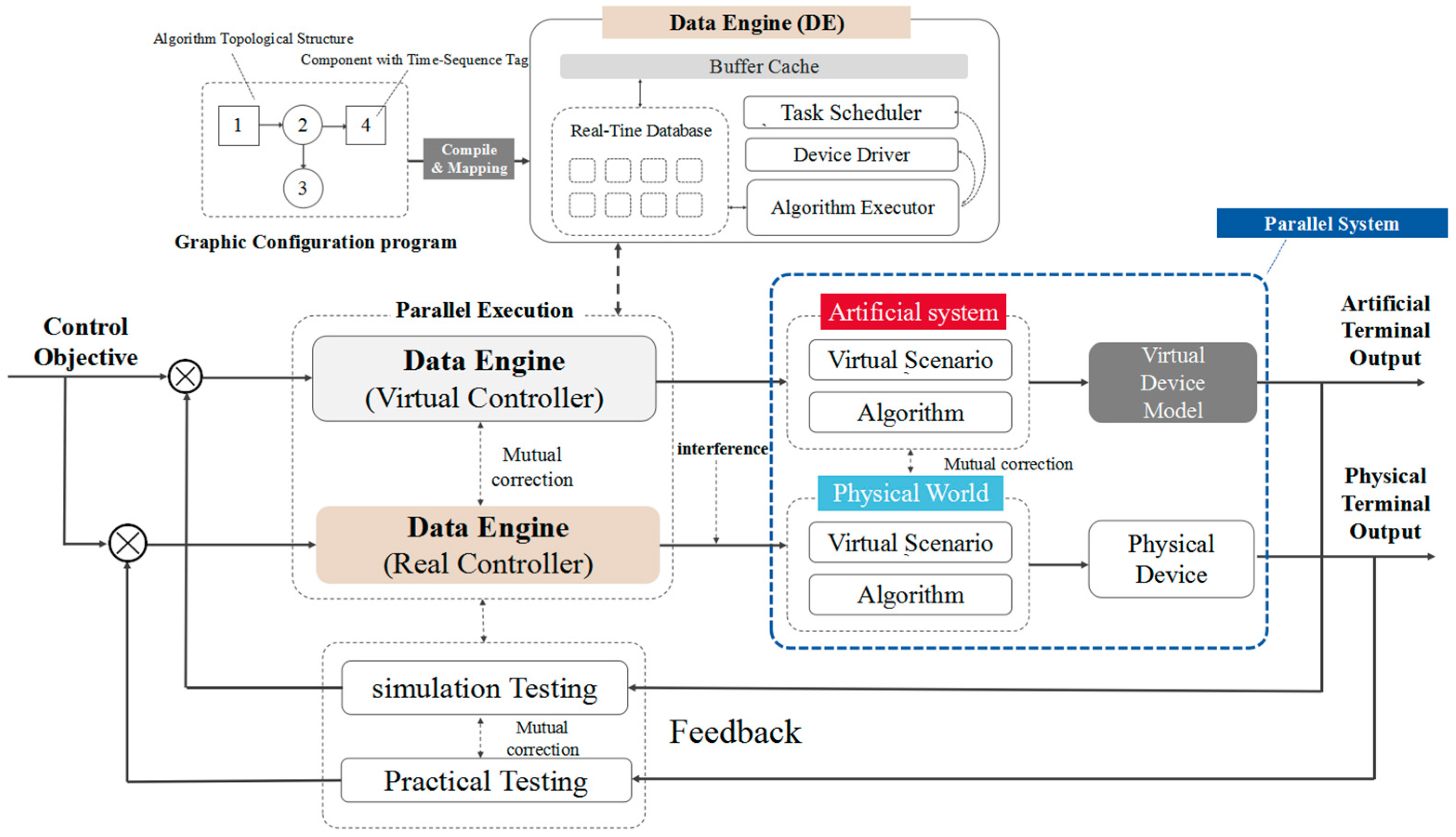
Figure 1 shows the basic architecture of the parallel system. By monitoring and comparing the output errors of the physical system and the artificial system, the parallel system uses continuous control experiments to guide and modify the physical system to achieve its goal; that is, making its output meet the specific requirements and be equivalent to the artificial system. This means that the computing environment of the artificial system and the physical system should be as consistent as possible. In this way, the value of the closed-loop parallel system formed by the connection of the physical system and artificial system can be adequately exploited.
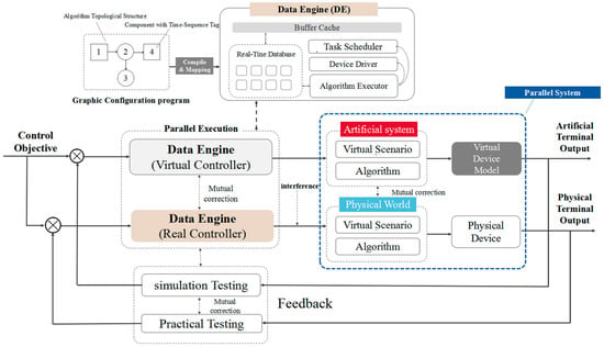
Figure 1.
The architecture of PWECS.
Nevertheless, in the past few decades, in the simulation system it has usually been difficult to represent the physical system or other possible solutions. One important reason is that their computing environments are not entirely equivalent. It is difficult and expensive to transplant the artificial system to the physical system and form an online closed-loop dynamic system. Data Engine technology creates favorable conditions to solve the above issue. It is an appropriate computing environment for fulfilling the needs of above. Data Engine consists of a real-time database based on memory and several data processing machines based on a multi-agent system (MAS), which can explain and drive the algorithmic data structure following a unified specification, as well as reconstruct the relationship of the control configuration data [34]. These data-processing machines include the algorithm executor, the task scheduling module and the buffer area. The MAS is regarded as the transaction processing mechanism of the real-time database. When the data in the real-time database changes, Data Engine can activate specific software agent independently, accept the application of relevant real-time data update and export the output data to external devices via data bus. Data Engine provides the data cache area to communicate with external devices. Through data cache area, Data Engine can output the real-time data into the programming configuration software to achieve the visualization computation, perform the undisturbed update of control algorithms without stopping the control system, and share data among different Data Engines during their computing process.
For the calculation principle, Data Engine can accept the configuration data transformed by component configurations and store them in the memory database. As a functional module encapsulating a specific algorithm, the component is essentially a type of computing unit with reusable, visualization and reconfigurable traits. There is a certain time-sequence relationship among components determined at the stage of graphical configurations. When the Data Engine works, the only thing needed is analyzing the topological relationship of the configuration data and calculating the component data individually according to the time sequence, which results in the periodic data update in the memory database. In this way, the control algorithm for wind power generation can be implemented by the graphical component configurations, as long as they can be converted into computable task units.
Data Engine is a type of control middleware which is used for replacing the original control software system and establishing a unified specification computing environment to explain and drive the data from heterogeneous devices by calling the internal data-driven interface of the system. Data Engine is irrelevant to the type of controllers and the control objects, which makes it possible to be deployed in different types of controllers, such as the PLC, IPC, and PC. Thus, from the algorithm execution level of view, the heterogeneity of control systems is further eliminated and the control algorithm can run on different structures of computational environment.
According to the characteristics of Data Engine, this is a scientific way to research the WECS by combining the parallel system theory with the Data Engine approach, which is also feasible in an engineering application. Figure 2 shows the software framework of PWECS, which is composed of two layers: the engineer layer and device layer. The device layer consists of different brands, function, and models of controllers and auxiliary devices of the wind energy control system which is embedded with Data Engine; the engineer layer is used to interact with the Data Engine for users. The available software mainly include the human machine interface software IAPview, the graphical configuration programming software IAPlogic, the data software IAPdata and the virtual controller IAPsimu. Among them, IAPlogic is responsible for the logical configuration of the control algorithm, fault diagnosis, dynamic reconfiguration, and real-time data monitoring. The data software IAPdata is used for historical data analysis, processing and hazard warning. IAPsimu is the key part of the software framework. It is a software based on Data Engine and can run on a PC to simulate the computing behavior of physical control stations and provide virtual-real interaction of real controllers. Due to the controller-independent characteristic of Data Engine, the controller software and the computing environment of artificial systems are completely consistent with the actual physical controller in essence, and the only difference is the performance of physical devices such as the central processing unit (CPU). In other words, the control logic running in the virtual controller IAPsimu can be downloaded to the real controller directly. Thus, in the artificial system which is constructed based on the Data Engine, the working processes and the control algorithms are equal to the physical system, which can be optimized by the artificial control object, and the parallel execution of artificial systems and physical systems will become more reliable, and the “equivalence” of these two systems can be reflected more objectively in the optimization of algorithm models. Moreover, in the virtual–actual interactive environment, the cost of complex system design and operation can also be significantly reduced by means of the component visualization and dynamic reconfiguration.
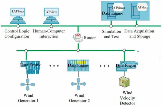
Figure 2.
The software framework of a parallel wind energy conversion system (PWECS).
The dynamic reconfiguration technology is used to ensure on-line updating of a control algorithm and undisturbed transformation of control system state [34]. In a PWECS system, we take the component as the control algorithm model and update the control configurations though many kinds of operations, including adding, deleting and replacing components, adjusting their topological relations and component parameters. When performing the algorithm reconfiguration of the control algorithms, the MAS will compare the differences between the new configuration data with the original data in a real-time database. Only the changed configuration data will be sent to the data cache area of Data Engine. When Data Engine receives the reconfiguration request, it only updates the changed data to the real-time database. Either the software process of Data Engine or the structure and location of algorithm variables in the memory will resume regular working. The content of parallel systems will become more diverse by using the dynamic reconfiguration method, and it makes artificial systems more proactive in guiding the running of physical systems.
4. The Artificial System of PWECS
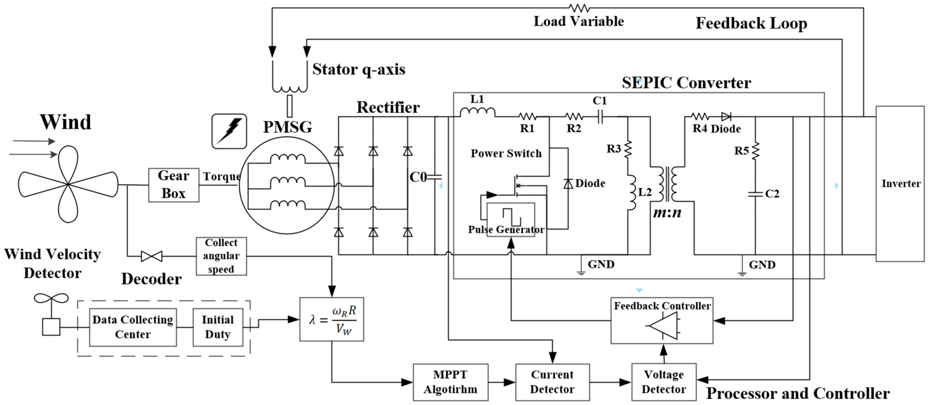
Figure 3 shows the control model of the artificial system in the PWECS. It is designed according to the actual engineering system, and the operation process and devices of the artificial system are consistent with the real one [37]. It mainly consists of a wind turbine (including fan impeller, hub and navigation cover), permanent magnet synchronous generator (PMSG), three-phase bridge rectifier, SEPIC module and inverter module. Among them, the wind turbine rotates under the driving wind and outputs mechanical energy. The rotor of the PMSG is driven by the shaft of the wind turbine, and the stator cuts the magnetic induction line to generate current under the rotating magnetic field, achieving secondary energy conversion that converts mechanical energy into electrical energy. Due to the frequency of the output current varying with the speed of the rotor, a three-phase bridge rectifier is used to convert the alternating current output from the PMSG into a direct current. After being filtered by the C0 capacitor, it provides a stable direct current (DC) power supply for the SEPIC module. The function of the SEPIC module is realized in the buck-boost of the direct current.
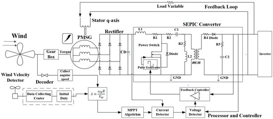
Figure 3.
The control model of the artificial systems in PWECS.
Supposing the mechanical output power is , from the kinetics of wind, the mechanical output power should be depicted by the formula [38]:
where the constant ρ indicates the air density, the constant R indicates the blade radius of the WECS, represents the speed of wind, and is the utilization coefficient of wind energy and the function between tip speed ratio λ and pitch angle ꞵ. The function can be defined as [39]:
In general, C1 = 0.5176, C2 = 116, C3 = 0.4, C4 = 5, C5 = 21, C6 = 0.0068. The tip speed ratio λ is the ratio between the tip speed and the wind speed [40]:
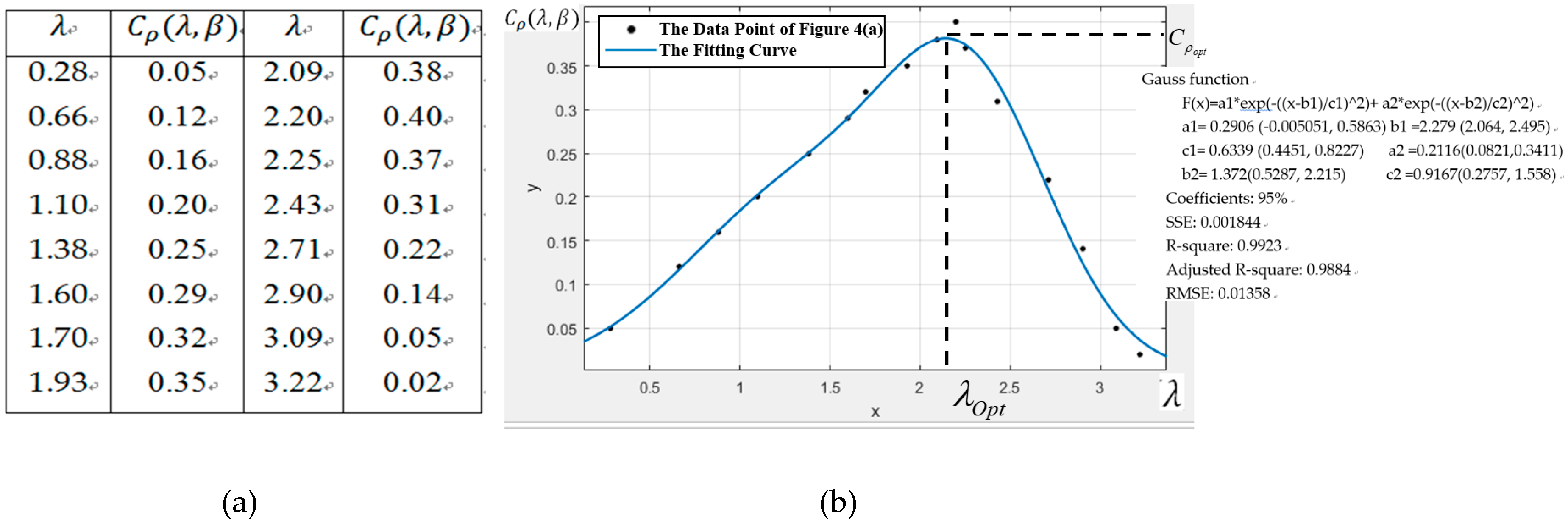
According to the Betz’s Law, will never be larger than 0.593. For simplicity, we have found out a set of specific data models for and λ which is shown in the Figure 4a. These parameters are measured from the real WECS which has a constant pitch angle ꞵ and have been testified in Reference [37]. Fitting these data points with the Gauss function, Figure 4b shows the functional relationship curves between and λ. From Figure 4b, there is a point that maximizes the value of , which is the optimal tip speed ratio . It means that the optimal tip speed ratio with corresponding angular speed can be illustrated as:
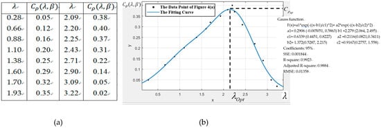
Figure 4.
(a) The data of the function between and λ; (b) The fitting curve of data points in Figure 4a.
Therefore, in order to capture the maximum power point of wind energy for improving the efficiency of PWECS, the speed of the generator needs to be controlled to keep the tip speed ratio λ at the point where is at the maximum under different wind velocities.
The torque of the wind turbine is defined as:
when the wind speed is constant, the torque is mainly determined by the power utilization coefficient .
In the PMSG, the center line of the permanent magnet rotor of synchronous rotating coordinate system is the straight d axis; the axis of the rotation direction ahead of the d axis is the cross q axis, and the torque equation of PMSG can be obtained:
In formula (7), means electromagnetic torque of PMSG, is the rotary damping coefficient of PMSG, and J is the rotary inertia of PMSG. When the stator winding rotates at speed under constant force, the induction electromotive force is given by the following formula:
Here, is a constant. Assuming that the inner synchronous reactance of the PMSG is and the inner synchronous resistance is , both of them may affect the output voltage [41]. Since the conduction angle of the rectifier bridge is set to 0, the input and output voltages of the bridge circuit are:
where is the current of the stator winding. In general, is quite small, so it is always be neglected. By using the Taylor formula, the formula (9) can be simplified to the formula (10), and is a small constant which approaches to 0 in formula (10).
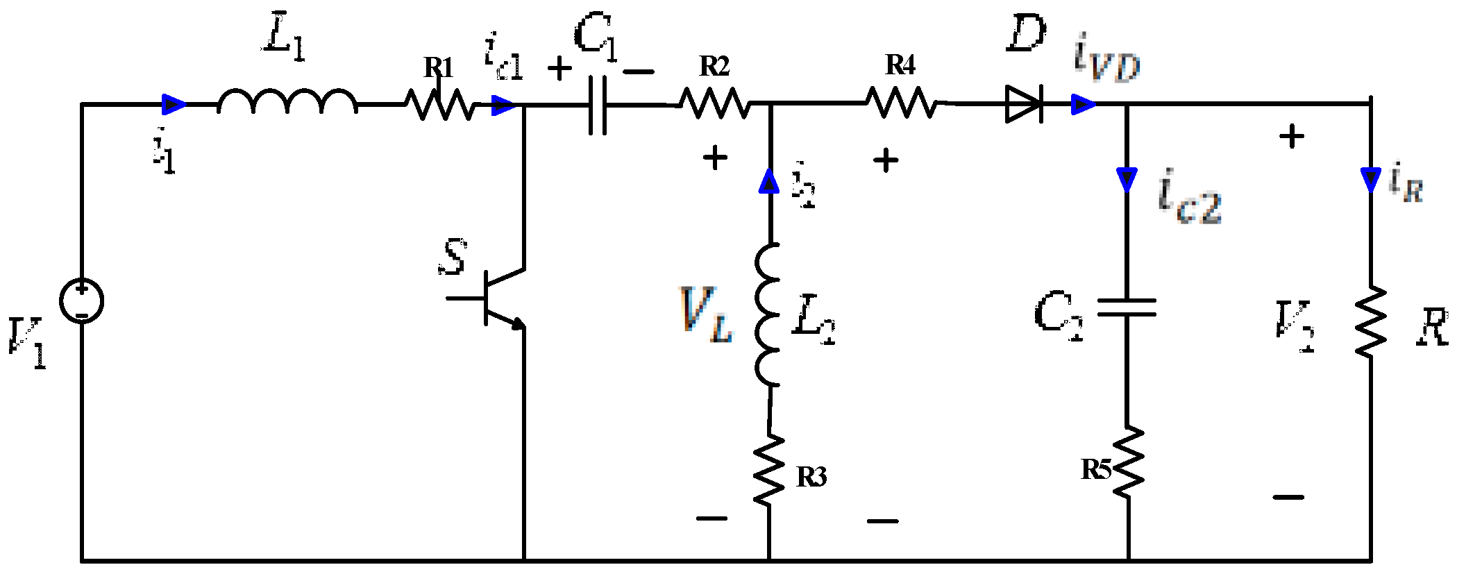
The DC voltage will be the supplement of the isolated SEPIC module. Figure 5 shows the equivalent circuit of the SEPIC module.
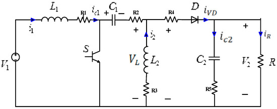
Figure 5.
The equivalent circuit of the SEPIC module.
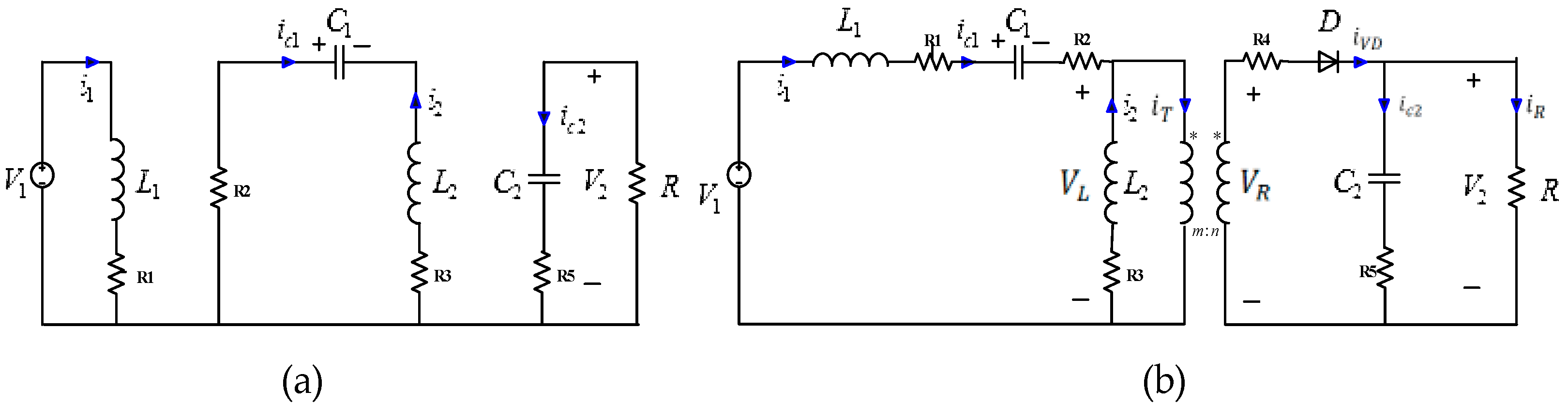
A common pulse width modulation (PWM) is used to control the switch S. In a continuous period, the SEPIC module can be divided into two cases, the corresponding circuits are shown in Figure 6.
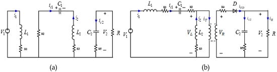
Figure 6.
The equivalent circuit of the SEPIC module when the switch is on or off: (a) power switch is on; (b) power switch is off.
When the Power Switch is on, the differential equations state of the SEPIC module is:
When the power switch is off, the differential equations state of the SEPIC module is:
Assuming that the duty cycle of PWM is α and the period is T, the conduction time is αT and the cut-off time is in a single cycle. The relationship between the input voltage and the output voltage is [42]:
Among them, is buck-boost value. Combining the formula (9), (10) and (13) could obtain the power captured by the PMSG:
From formula (14), we can know that the maximum power of PMSG can be tracked by controlling the duty cycle of the switch S of the SEPIC.
5. The Configuration of PWECS
In the PWECS, the operation process of artificial WECS is consistent with the real one. The algorithms and models of the information control process of artificial WECS are submitted to computing environment formed by the Data Engine. Unlike other management or control platforms, the device models, control algorithms, service processing, and other functions in the PWECS are implemented by the combination of a plurality of graphical components. Since the calculation process of components is visible and periodically updated, the internal composition of the system model and the computation process of control algorithms can be monitored dynamically.
Data Engine technology encapsulates all the processing of data model including data management and data calculation into a graphical data operation mechanism. On the basis of this technology, all kinds of control models and problems can be transformed into graphical component configuration issues for processing, and the control case of WECS in an actual industrial field can be graphically transformed into a theoretical calculation model and a logical relation of the data model. In order to identify the basic component prototypes of algorithm modules or structures in PWECS, the general structure of PWECS is modularized and decomposed to find the best component granularity from the system structure. That is, decomposing the key modules from the mathematical model, distinguishing independent algorithm modules or structures according to the limitations of data engine technology, and checking the reusability of the key module algorithm. The granularity of the component is critical for the process of configuring the control algorithm. If the selection of component granularity is too small, that will reduce the calculation scale of each component, but the complexity of the connection relationship between the components and the difficulty of control configuration programming will be increased. Otherwise, the data unit capacity of the Data Engine will be insufficient, and the critical system state cannot meet the requirements of real-time monitoring.
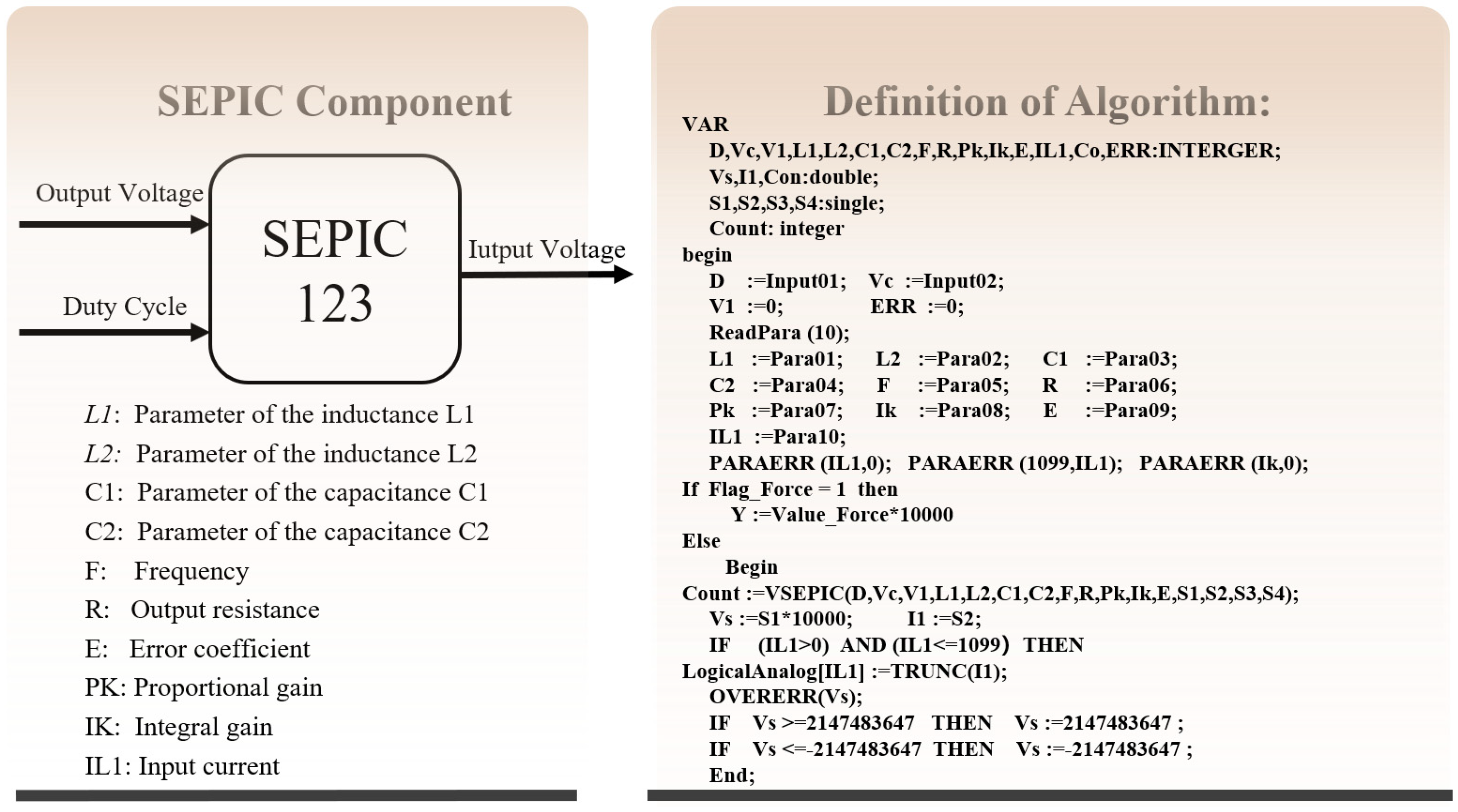
For example, the complexity of the SEPIC module lies in the calculation of intermediate variables in PWECS. If the components are used to encapsulate the intermediate calculation process and the control parameters are set through the interface, it is very beneficial to reduce the complexity of the system design and development and improve the deployment efficiency. Therefore, this paper develops a SEPIC control configuration component called SEPIC123, which is shown in Figure 7. According to its algorithm definition, the input–output relationship is clear and the internal structure is encapsulated completely. This component can be invoked in the configuration programs of two utterly unrelated variables simultaneously: the output voltage and the duty cycle. This is where the reusable components play a role, i.e., using sophisticated computing resources to complete different computing tasks. In this case, we do not need to write code and replace it with graphic configuration mode to setup the algorithm for specific agent services. We only need to adjust the parameters of the components according to the actual conditions without knowing the internal functions.
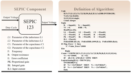
Figure 7.
The definition of algorithm and parameters of SEPIC component.
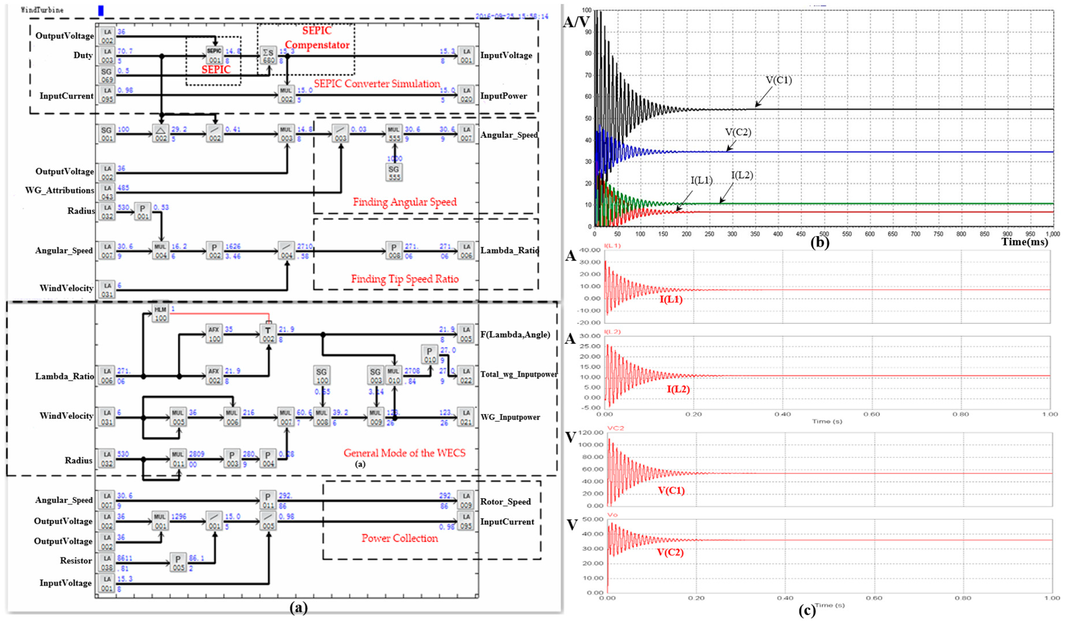
The part control logic of the artificial system of PWECS on IAPlogic is shown in Figure 8. The control strategy is programmed by connecting graphical components which map the system architecture of an artificial system. This process uses 60 components and provides 18 input signals of real-time collection data and 11 outputs of the control algorithm. It contains five parts: SEPIC converter simulation, angular speed finding, tip speed ratio finding, general model of the WECS, and the power collection. All input variables are in the leftmost column, and all output variables are in the rightmost column. Thus, the logical correspondence between input and output can be easily deduced by calculating the intermediate algorithm component, for instance, assigning the value for the duty cycle component LA003 and the expected output voltage component LA002, then transmitting them to the component SEPIC001 for calculating the input voltage of the SEPIC module (the parameters of the SEPIC are listed in Table A1 in the appendix). The resulting configuration relationships will be downloaded to the Data Engine to perform calculations, and the real-time value of each component can be dynamically fed back into the configuration program interface. The upper right corner of Figure 8 is the dynamic current curves of inductors L1, L2 and dynamic voltage curves of capacitors C1, C2 when the power switch is on and off, and the lower right corner of Figure 8 shows the simulation results on the MATLAB software under the same conditions. By comparing the curves, it is found that the test results of the SEPIC component are consistent with the simulation results of MATLAB, which verifies the feasibility of the component.
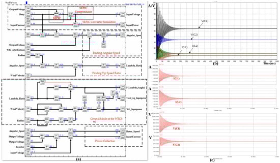
Figure 8.
(a) The parts of control logical configuration of WECS system; (b) The dynamic current curves of inductors L1, L2 and dynamic voltage curves of capacitors C1, C2 when the power switch is on and off; (c) The simulation results on the MATLAB software under the same conditions.
6. The Maximum Power Point Tracking (MPPT) Experimental Case of PWECS
This study designs and develops a virtual artificial system equivalent to the physical system to verify the effectiveness of parallel systems established by Data Engine in the field of WECS. In our research, the MPPT computational experiment is carried out to obtain the technicality of parallel systems and to guide the management and control of the actual system. We adapt the hill-climbing method to track the maximum power point of the artificial system. The hill-climbing method does not need to measure the wind speed, the characteristic coefficients of the wind turbine, and the generator in advance, which brings great convenience to the calculation process.
The calculation principle of the uniform hill-climbing method is increasing or decreasing a fixed disturbed value, observing the variation trend of the power point. If the power point increases, the disturbed value will be maintained. Otherwise, the direction of the disturbed value will be changed, and it will calculate cyclically until the power point remains constant and reaches the maximum. However, the fixed disturbance is usually set based on engineering experience. If the disturbance is too small, it will affect the tracking speed of the maximum power point which reduces the system efficiency, or the system will produce oscillations which cause power loss.
The variable hill-climbing method is designed to overcome the shortcomings and improve the tracking speed of a uniform climbing algorithm. When the power point is far from the maximum power point, the disturbance value should be increased to speed up the climbing speed; otherwise, the disturbance value should be reduced so as to slow down the climbing speed, and the disturbance will stop until the maximum power point is reached. To achieve the above process, the disturbed value νhill is used as the control deviation and the power difference ΔP are processed as the control variable to establish PI controller.
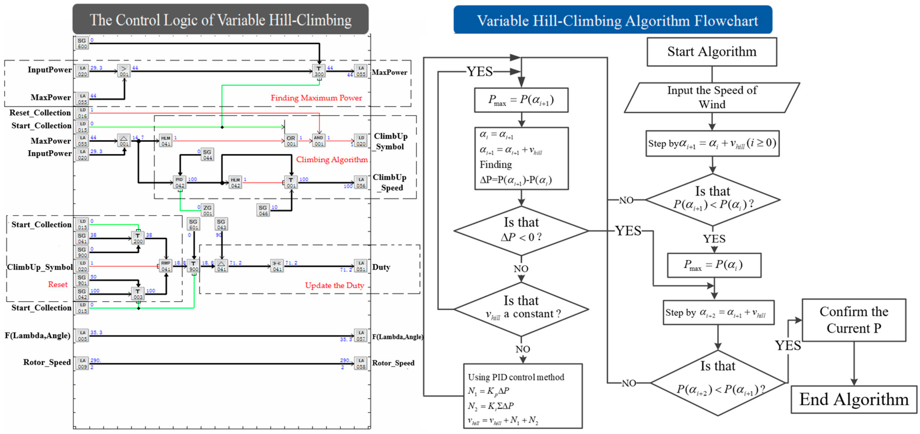
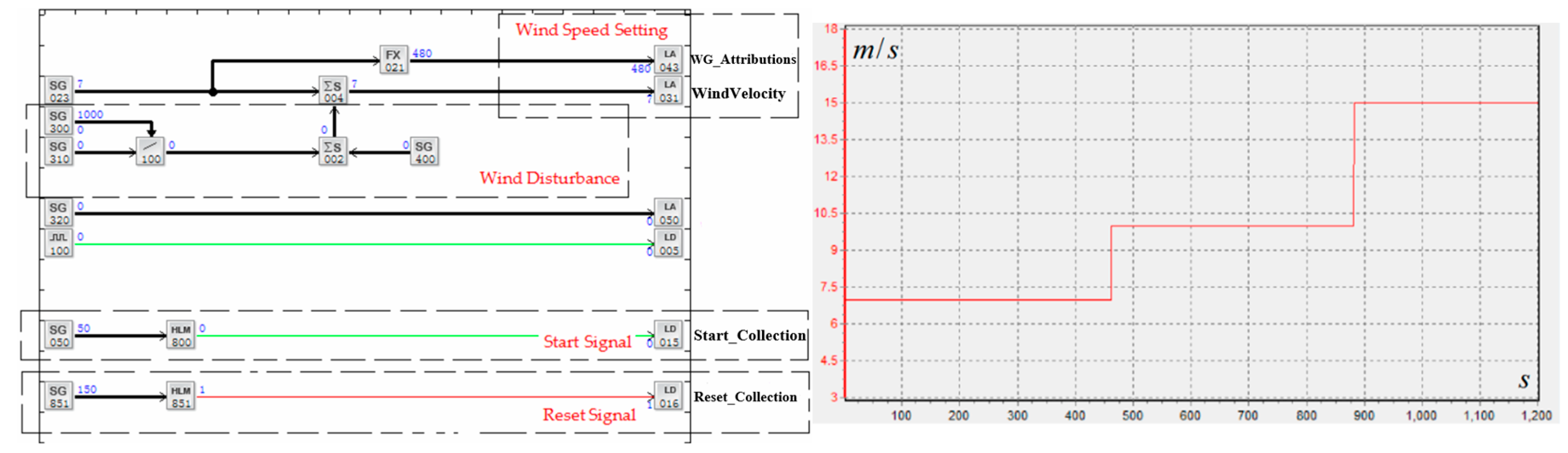
The algorithm flowchart and control logic of variable hill-climbing are presented in Figure 9. The control logic contains four parts: finding maximum power, the climbing algorithm, updating the duty, and the reset signal. The larger power value at the time of the front and back (LA020 and LA055) is obtained by using the comparison component. After making a difference between them, the difference result can be used as the input value of the threshold component HLM041 to determine whether the power point reaches the maximum. The difference connects to a PID component and is regarded as the control deviation. Like the SEPIC component, the PID component executes an internal algorithm according to the parameter configuration, and the output values of the PID component will be used as the disturbed value. This means that the duty cycle component LA051 will change according to the hill-climbing rate when the power value component LA055 does not reach the maximum. With the help of dynamic reconfiguration technology, the component T001 has the function of output compulsion. The uniform hill-climbing algorithm can be implemented when the output value of the component T001 is forced into a specific value and the wind speed component SG023 can be set on-line to achieve the purpose of continuous calculation of PWECS. The logical configuration of wind speed setting and the tendency chart for the wind speed modification process are shown in Figure 10. Setting the start collection signal as 0 and reset collection signal as 1, the procedure will execute automatically.

Figure 9.
The algorithm flowchart and control logic of variable hill-Climbing.
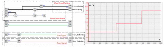
Figure 10.
(a) The logical configuration of wind speed setting; (b) The tendency chart for wind speed modification process.
According to our previous work [43,44,45,46,47], Data Engine embeds a variety of communication protocols and can be deployed in heterogeneous computing environments. To prove that the parallel system based on Data Engine has the characteristic of integration of simulation and engineering applications, this paper uses the IPC of SoonCCI (SQL-IPC-S2221) as the computing environment of the parallel system and downloads the control logic of the artificial system into it to track the maximum power point. Although the physical system contains a large number of automatic regional equipment, the artificial system has also constructed the virtual equipment, proportional virtual scenes, work processing, and control strategies. The algorithms and models in these processes are entirely consistent in their implementation environment and methods. Two systems are exactly the same regarding to the system equipment, communication and database composition as well as the overall function, except for the source of the operation data, i.e., one from the actual devices and the other from the model system. During the calculative experiments, the dynamic calculation process of the maximum power point in the artificial system can be observed. After the actual system being constructed, we only need to modify the data sources of the Data Engine to present the actual running status dynamically. It means that users can connect IPC to the actual device by calling relevant communication protocols and test the control algorithms. For example, the IPC can read the wind speed from the relevant actual sensors by invoking the communication protocol and assigning this value to component SG023.
7. Results and Discussions
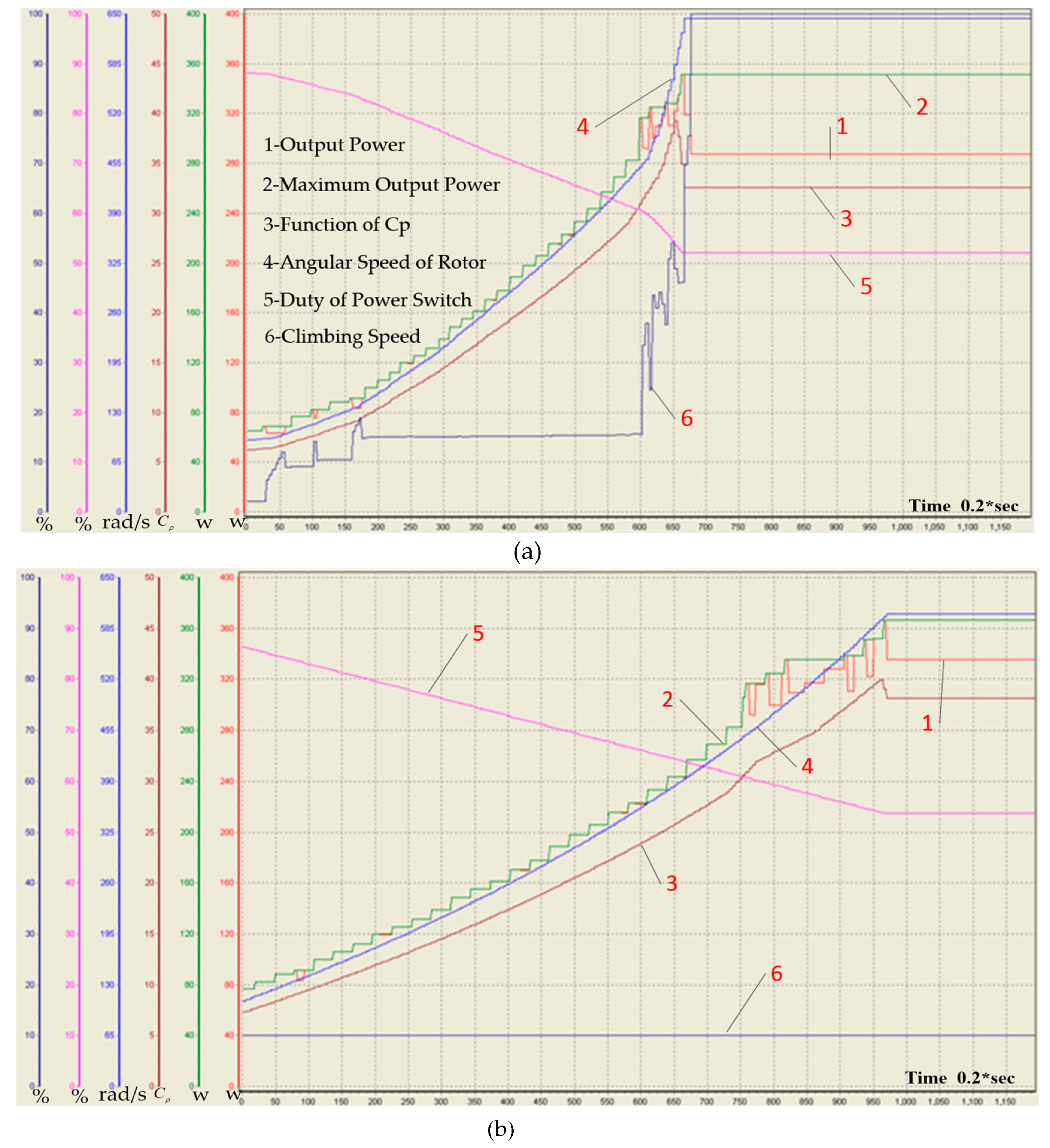
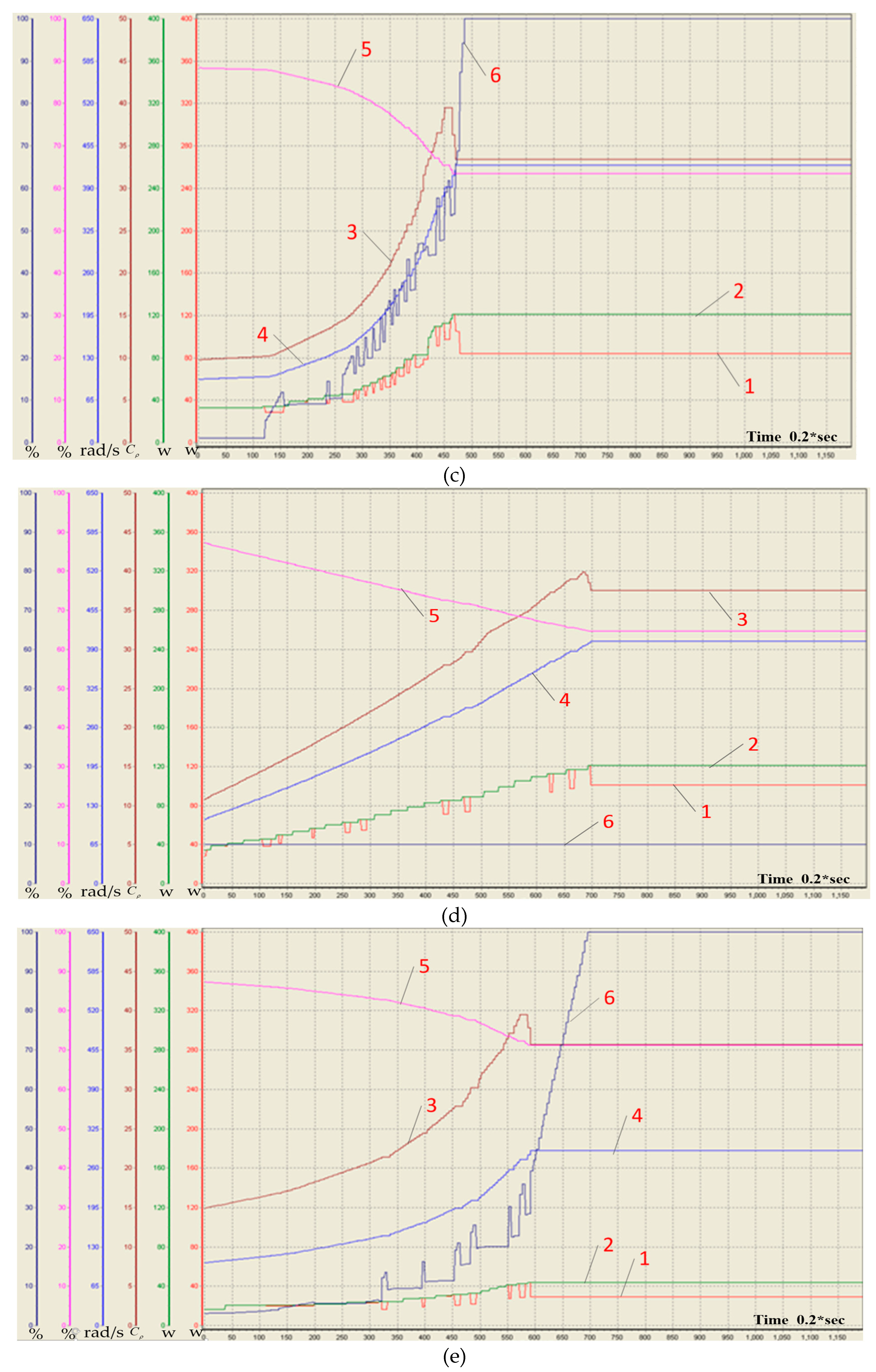
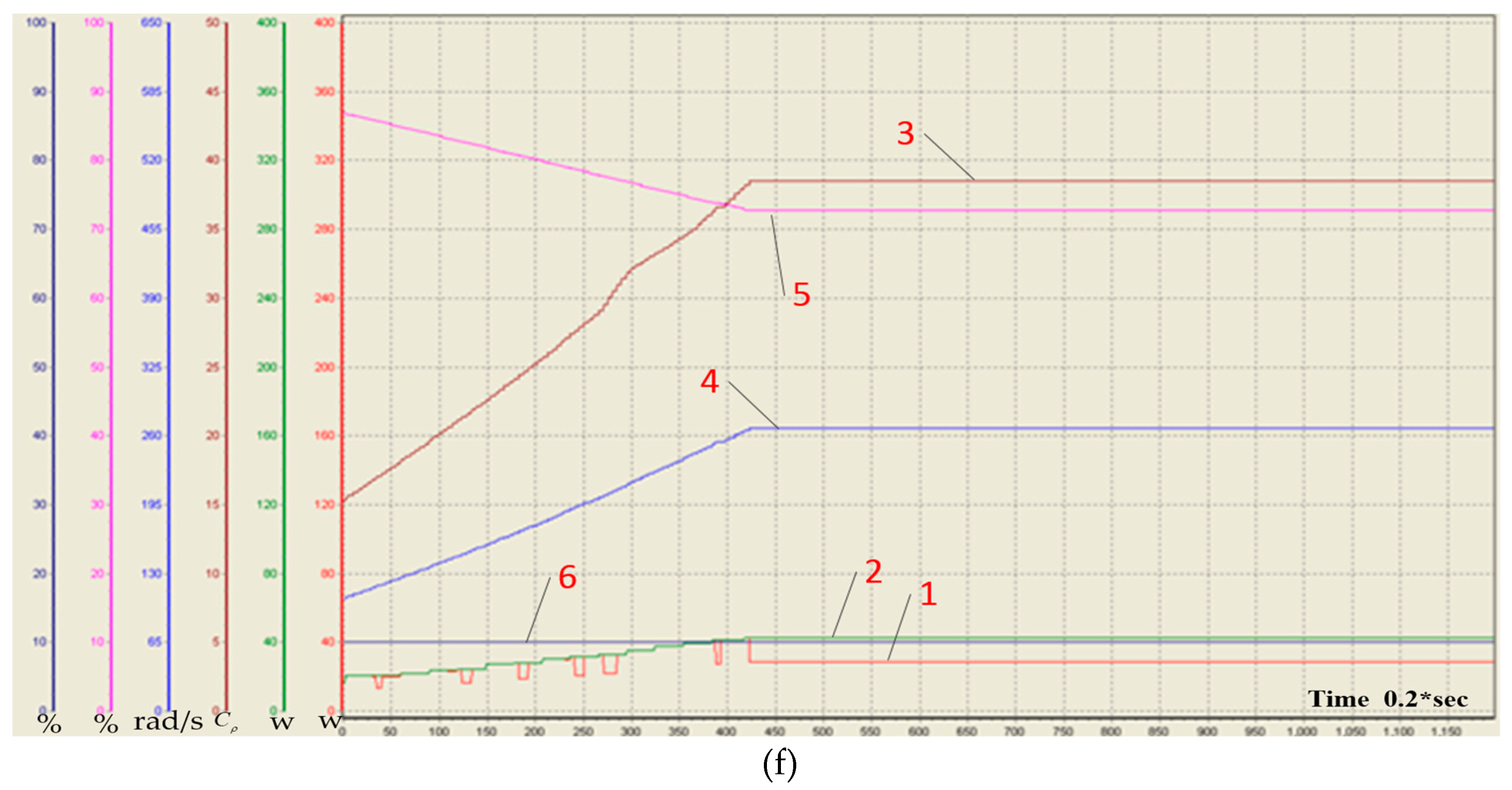
The tendency chart of the output power, the maximum output power of PMSG, the utilization coefficient of wind energy, the angular speed of PMSG, the duty cycle and the climbing speed at a wind speed of 15 m/s, 10 m/s and 7 m/s of uniform hill-climbing and the variable hill-climbing are recorded in Figure 11, and Table 1 displays experimental results between them.
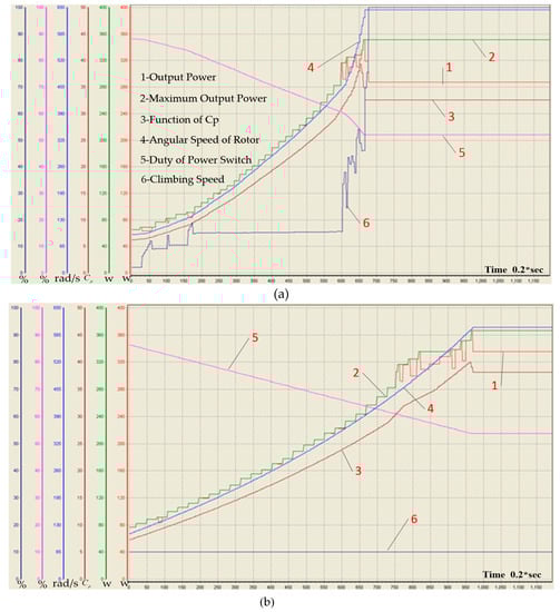
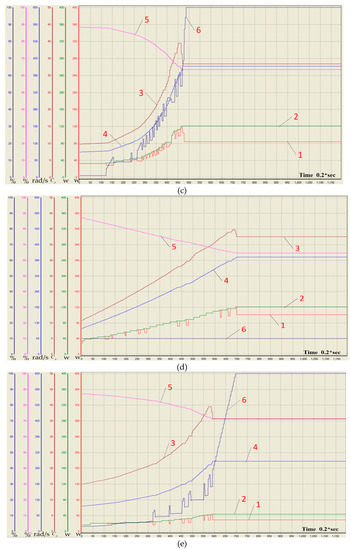
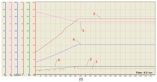
Figure 11.
The tendency chart of relevant data in PWECS: (a), (c) and (e) are the variable hill-climbing when the speed of the wind at 15 m/s, 10 m/s and 7 m/s; (b), (d) and (f) are the uniform hill-climbing when the speed of the wind is at 15 m/s, 10 m/s and 7 m/s.

Table 1.
The experimental results of the uniform hill-climbing and the variable hill-climbing method.
From the above, the maximum output power of PMSG is approximately the same. Under the wind speed of 15 m/s and 10 m/s, it takes less time to reach the maximum power point by the variable hill-climbing algorithm than by the uniform hill climbing algorithm, but the output power is smaller. In the case of 7 m/s wind speed, it takes more time to reach the maximum power by using the variable hill-climbing algorithm, and the output power is basically the same. The experimental results show that the uniform climbing method and the variable speed climbing method have different performance advantages under different wind speeds, and we can use different climbing algorithms at different wind speed.
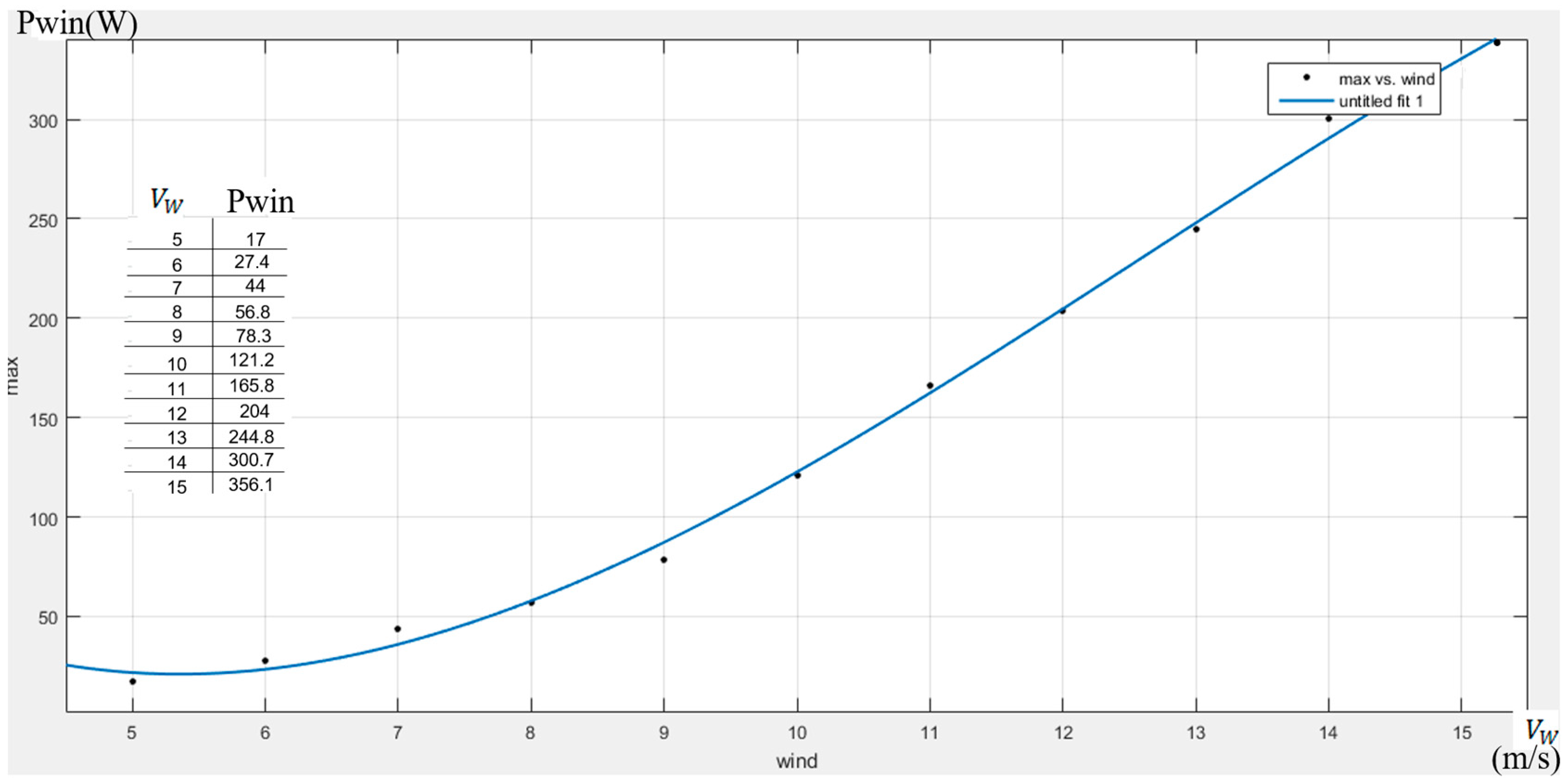
Figure 12 shows the fitting curve of the maximum output power of the PMSG calculated by the variable hill-climbing algorithm when the speed of wind velocity is 7–15 m/s. The curve satisfies the typical maximum output power locus [48].

Figure 12.
The fitting curve of the maximum output power of PMSG.
The experimental results also show that the designed parallel system can optimize and test the management and control strategy of the WECS dynamically through on-line calculation experiments, providing scientific clues to design the control strategy of a real system. This is very important in saving work time and energy of the WECS.
In addition, the virtual computing environment also can be used to conduct many calculative experiments in parallel space. For example, in order to improve operation efficiency and reduce energy consumption, the system can design an optimal scheme to guide the safe operation of the real system. For such dynamic tests, it is almost impossible or costly to adopt traditional control platforms and approaches.
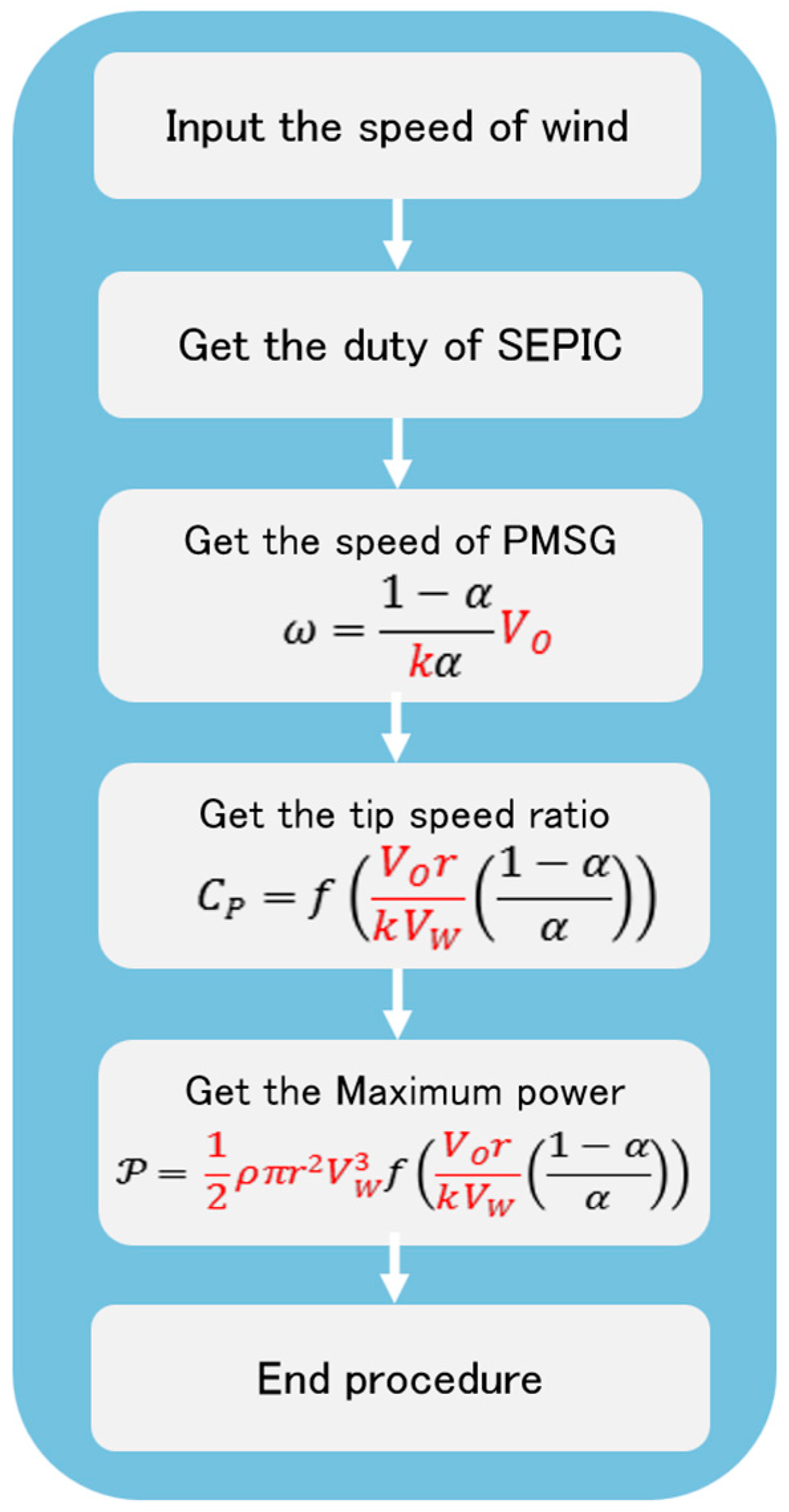
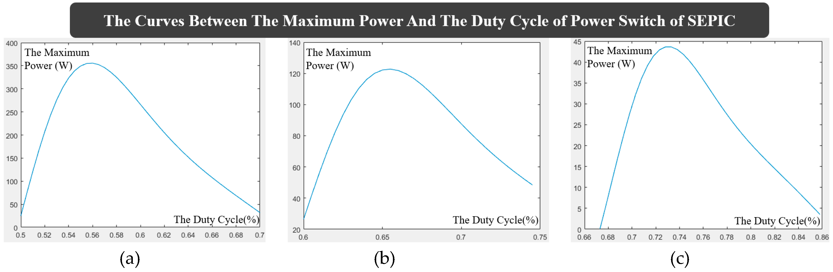
To demonstrate the feasibility and scientificity of the PWECS, we validate the experimental result on the MATLAB platform. According to the procedure flowchart of Figure 13, we calculate the relevant parameters on the MATLAB platform (the constant marked red in the procedure flowchart is the same as the parallel WECS). Figure 14 shows the functional curves between duty cycle and maximum output power of WECS on MATLAB under different wind speeds. Comparing with the data in Table 1, the calculation results on MATLAB platform are almost the same as those on PWECS. Table 2 shows the comparison of calculation results between PWECS and MATLAB.
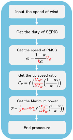
Figure 13.
WECS simulation modeling flow chart
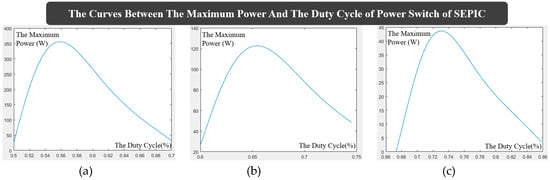
Figure 14.
Curves between the maximum power and the duty cycle of power switch of SEPIC on the MATLAB platform: (a) when the wind velocity is 15 m/s; (b) when the wind velocity is 10 m/s; (c) when the wind velocity is 7 m/s.
Table 2.
The comparison of calculation results between PWECS and MATLAB
The calculation results show that the error between the two platforms is in a small range, which can explain the effectiveness and the stability of computing and modeling for the PWECS. The PWECS can be deployed in a heterogeneous controlled way and integrate multiple devices, and is established by the unified, graphical software. The graphical configuration is relatively intuitive, and the data process is transparent, that is, the data processed can be visually presented in the software interface, and has a dynamic reconfiguration characteristic. Therefore, the PWECS reflects more advanced technical characteristics.
8. Conclusions
How to improve system performance of WECS is a critical technical trend in wind energy application research at present. The parallel system theory is an effective method to solve it, but there still needs to be an effect and scientific system architecture to improve its technical maturity and shorten the deployment cycle of the engineering application. The main contribution of this paper is to propose a parallel wind energy conversion system architecture (PWECS) based on the parallel system theory and the Data Engine approach. Data Engine is an ideal software implementation method for the parallel system theory. It provides a virtual–actual interaction computing environment for the parallel system, and makes the artificial system of a parallel system completely consistent with the actual physical controller, which not only improves the WECS control quality, but also fulfils the potential of the Data Engine computing environment effectively.
After we constructed a PWECS and carried out MPPT computing experiment. The results show that the PWECS system is feasible both in theory and engineering applications. It effectively reduces the difficulty and the cost of the development and deployment of the WECS and improves the reliability of the application of a physical system algorithm in engineering. The system has the characteristics of visualization and dynamic configuration, which is helpful for realizing the on-line optimization of the physical system and makes its output approach the “artificial system” with better effect. The system also provides a unified, graphical and modular control configuration which improves the efficiency of system development and makes heterogeneous devices perform a collaborative control.
At present, the PWECS has been preliminarily applied, but it is still in the initial stage. The simplified control models of WECS are used to verify the feasibility and effectiveness of PWECS, which lack verification in actual equipment. In addition, how to design and apply advanced control algorithms in PWECS is another problem worthy of further study. On the basis of this paper, future research should be carried out in physical systems including the data acquisition system and the drive execution system, and more classical and advanced WECS control algorithms should be tested and applied to cope with the more complex physical information environment.
Author Contributions
This paper is the results of the work of all authors. Z.L. conceived and developed the architecture of PWECS, performed and the experiments, and contributed to the writing of the manuscript. S.Z. provided guidance and direction for the implementation, development and evaluation of this research. Z.C. and R.Z. contributed to writing review and editing the manuscript. W.Z. contributed in bibliographical research, analysis and discussions of the results and the software development.
Funding
This work was funded by the Fuzhou Science and Technology Project Foundation of China, grant number 2017-G-70.
Acknowledgments
The authors would like to thank the editors and the reviewers for their hard work during the review process.
Conflicts of Interest
The authors declare no conflict of interest.
Appendix A
Table A1.
Parameter Settings of SEPIC Configuration Component.
Table A1.
Parameter Settings of SEPIC Configuration Component.
| L1,L2 | C1,C2 | F | R | VC2 | E | PK | IK | IL1 |
|---|---|---|---|---|---|---|---|---|
| 216 mH | 444 uF | 10 kHz | Pwin/V2 | 36 v | 1000 | 200 | 5 | 11 |
References
- Kumar, Y.; Ringenberg, J.; Depuru, S. Wind energy: Trends and enabling technologies. Renew. Sustain. Energy Rev. 2016, 53, 209–224. [Google Scholar] [CrossRef]
- Willis, D.J.; Niezrecki, C.; Kuchma, D. Wind Energy Research: State-of-the-Art and Future Research Directions. Renew. Energy 2018, 125, 133–154. [Google Scholar] [CrossRef]
- Astolfi, D.; Castellani, F.; Terzi, L. Wind Turbine Power Curve Upgrades. Energies 2018, 11, 1300. [Google Scholar] [CrossRef]
- Wei, C.; Zhang, Z.; Qiao, W.; Qu, L. An Adaptive Network-Based Reinforcement Learning Method for MPPT Control of PMSG Wind Energy Conversion Systems. IEEE Trans. Power Electron. 2016, 31, 7837–7848. [Google Scholar] [CrossRef]
- Imran, R.M.; Hussain, D.M.A.; Chowdhry, B.S.; Clare, J.; Asher, G. Dynamic Modeling and Robust Controllers Design for Doubly Fed Induction Generator-Based Wind Turbines under Unbalanced Grid Fault Conditions. Energies 2018, 11, 1296. [Google Scholar] [CrossRef]
- Farhad, I.B.; Dheeraj, K.K. A new synchronous generator based wind energy conversion system feeding an isolated load through variable frequency transformer. Renew. Energy 2016, 86, 106–116. [Google Scholar]
- Wang, F.Y. Parallel system methods for management and control of complex systems. Control Decis. 2004, 19, 484–485. [Google Scholar]
- Wang, F.Y.; Liu, D.R.; Xiong, G.; Cheng, C.J.; Zhao, D.B. Parallel Control Theory of Complex Systems and Applications. Complex Syst. Complex. Sci. 2012, 9, 1–12. [Google Scholar]
- Wang, F.Y. Parallel Control: A Method for Data-Driven and Computational Control. Acta Autom. Sin. 2013, 39, 293–302. [Google Scholar] [CrossRef]
- Fathabadi, H. Novel high efficient speed sensorless controller for maximum power extraction from wind energy conversion systems. Energy Convers. Manag. 2016, 123, 392–401. [Google Scholar] [CrossRef]
- Xiao, F.; Zhan, C.; Lai, H. Parallel processing data streams in complex event processing systems. In Proceedings of the IEEE Control & Decision Conference, Chongqing, China, 28–30 May 2017. [Google Scholar]
- Chatterjee, K.; Kumar, D. A review of conventional and advanced MPPT algorithms for wind energy systems. Renew. Sustain. Energy Rev. 2016, 55, 957–970. [Google Scholar]
- Tiwari, R.; Babu, N.R. Recent developments of control strategies for wind energy conversion system. Renew. Sustain. Energy Rev. 2016, 66, 268–285. [Google Scholar] [CrossRef]
- Al-Falahi, M.D.A.; Jayasinghe, S.D.G.; Enshaei, H. A review on recent size optimization methodologies for standalone solar and wind hybrid renewable energy system. Energ. Convers. Manag. 2017, 143, 252–274. [Google Scholar] [CrossRef]
- Tripathi, S.M.; Tiwari, A.N.; Singh, D. Grid-integrated permanent magnet synchronous generator based wind energy conversion systems: A technology review. Renew. Sustain. Energy Rev. 2015, 51, 1288–1305. [Google Scholar] [CrossRef]
- Lee, S.W.; Chun, K.H. Adaptive Sliding Mode Control for PMSG Wind Turbine Systems. Energies 2019, 12, 595. [Google Scholar] [CrossRef]
- Jain, B.; Jain, S.; Nema, R.K. Control strategies of grid interfaced wind energy conversion system: An overview. Renew. Sustain. Energy Rev. 2015, 47, 983–996. [Google Scholar] [CrossRef]
- Lasheen, A.; Elshafei, A.L. Wind-turbine collective-pitch control via a fuzzy predictive algorithm. Renew. Energy 2016, 87, 298–306. [Google Scholar] [CrossRef]
- Wu, X.; Ma, Z.; Rui, X.; Yin, W.; Zhang, M.; Ji, K. Speed Control for the Continuously Variable Transmission in Wind Turbines Under Subsynchronous Resonance. Iran. J. Sci. Technol. Trans. Mech. Eng. 2016, 40, 151–154. [Google Scholar] [CrossRef]
- Krathe, V.L.; Kaynia, A.M. Implementation of a non-linear foundation model for soil-structure interaction analysis of offshore wind turbines in FAST. Wind Energy 2017, 20, 695–712. [Google Scholar] [CrossRef]
- Wang, C.S.; Chiang, M.H. A Novel Dynamic Co-Simulation Analysis for Overall Closed Loop Operation Control of a Large Wind Turbine. Energies 2016, 9, 637. [Google Scholar] [CrossRef]
- Bhattacharjee, S.; Acharya, S. Performative analysis of an eccentric solar–wind combined system for steady power yield. Energy Convers. Manag. 2016, 108, 219–232. [Google Scholar] [CrossRef]
- Gao, F.; Wu, X.; Liu, Q.; Liu, J.; Yang, X. Fault Simulation and Online Diagnosis of Blade Damage of Large-Scale Wind Turbines. Energies 2019, 12, 522. [Google Scholar] [CrossRef]
- Zoghlami, M.; Kadri, A.; Bacha, F. Analysis and Application of the Sliding Mode Control Approach in the Variable-Wind Speed Conversion System for the Utility of Grid Connection. Energies 2018, 11, 720. [Google Scholar] [CrossRef]
- Priyadarshi, N.; Ramachandaramurthy, V.K.; Padmanaban, S.; Azam, F. An Ant Colony Optimized MPPT for Standalone Hybrid PV-Wind Power System with Single Cuk Converter. Energies 2019, 12, 167. [Google Scholar] [CrossRef]
- The MathWorks Inc. Simulink PLC Coder User’s Guide. Available online: www.mathworks.com/products/sl-plc-coder/whatsnew.html (accessed on 27 February 2019).
- Shen, D.K.; Yang, X.; Chen, H.X. Research on Temperature Control System in a Hermetic Chamber with Discrete Heaters Based on Fuzzy Control by OPC Technology. In Proceedings of the IEEE International Symposium on Computational Intelligence & Design, Hangzhou, China, 12–13 December 2017. [Google Scholar]
- Yang, X.; Xu, W. Analysis on Safety Chain Circuit of Wind Turbine and Discussion on Safety Control Strategy. Dongfang Turbine 2016, 4, 64–69. [Google Scholar]
- Yang, X.; Liu, G.; Li, A.; Dai, L.V. A Predictive Power Control Strategy for DFIGs Based on a Wind Energy Converter System. Energies 2017, 10, 1098. [Google Scholar] [CrossRef]
- Zhang, M.; Liang, J.; Sun, Y.; Li, Q.; Ling, Z.B. Control System Hardware Design of Distributed Wind Turbine-Energy Storage System. Electr. Power Constr. 2016, 37, 149–154. [Google Scholar]
- Ni, K.; Hu, Y.; Liu, Y.; Gan, C. Performance Analysis of a Four-Switch Three-Phase Grid-Side Converter with Modulation Simplification in a Doubly-Fed Induction Generator-Based Wind Turbine (DFIG-WT) with Different External Disturbances. Energies 2017, 10, 706. [Google Scholar] [CrossRef]
- Shahbazi, M.; Saadate, S.; Poure, P.; MohammadReza, Z. Open-circuit switch fault tolerant wind energy conversion system based on six/five-leg reconfigurable converter. Electr. Power Syst. Res. 2016, 137, 104–112. [Google Scholar] [CrossRef]
- Kun-Feng, W.; Chao, G.; Fei-Yue, W. Parallel Vision: An ACP-based Approach to Intelligent Vision Computing. Acta Autom. Sin. 2016, 42, 1490–1500. [Google Scholar]
- Zheng, S.; Ni, W. Research and implementation of dynamic reconfiguration technology in distributed control system. Energy Sci. Technol. 2009, 43, 724–729. [Google Scholar]
- Duan, Y.J.; Lv, Y.S.; Zhang, J. Deep Learning for Control: The State of the Art and Prospects. Acta Autom. Sin. 2016, 42, 643–654. [Google Scholar]
- Bai, T.X.; Wang, S.; Shen, Z.; Cao, D.P.; Zheng, N.N.; Wang, F.Y. Parallel Robotics and Parallel Unmanned System: Framework, Structure, Process, Platform and Applications. Acta Autom. Sin. 2017, 43, 161–175. [Google Scholar]
- Wu, T.W. Design and Implementation of Maximum-Power-Point-Tracking Charger Based on a SEPIC Converter for Wind Turbine Generators; Minghsin University of Science and Technology: Taiwan, China, 2010. [Google Scholar]
- Lakshmi, M.J.; Babu, Y.S.K.; Babu, P.M. PMSG Based Wind Energy Conversion System for Maximum Power Extraction. In Proceedings of the IEEE Second International Conference on Computational Intelligence & Communication Technology, Ghaziabad, India, 12–13 February 2016. [Google Scholar]
- Hussain, J.; Mishra, M.K. Adaptive Maximum Power Point Tracking Control Algorithm for Wind Energy Conversion Systems. J. IEEE Trans. Energy Convers. 2016, 31, 697–705. [Google Scholar] [CrossRef]
- Vaz, J.R.P.; Wood, D.H. Performance analysis of wind turbines at low tip-speed ratio using the Betz-Goldstein model. Energy Convers. Manag. 2016, 126, 662–672. [Google Scholar] [CrossRef]
- Abbes, M.; Allagui, M. Participation of PMSG-based wind farms to the grid ancillary services. J. Electr. Power Syst. Res. 2016, 136, 201–211. [Google Scholar] [CrossRef]
- Jabbari, A.H.; Yoon, J. Power capture optimization of variable-speed wind turbines using an output feedback controller. Renew. Energy 2016, 86, 517–525. [Google Scholar] [CrossRef]
- Zheng, S.; Lin, Z.; Zeng, Q.; Zheng, R.; Liu, C.; Xiong, H. IAPcloud: A Cloud Control Platform for Heterogeneous Robots. IEEE Access 2018, 6, 30577–30591. [Google Scholar] [CrossRef]
- Zheng, S.; Zhang, Q.; Zheng, R.; Huang, B.Q.; Song, Y.L.; Chen, X.C. Combining a Multi-Agent System and Communication Middleware for Smart Home Control: A Universal Control Platform Architecture. Sensors 2017, 17, 2135. [Google Scholar] [CrossRef] [PubMed]
- Zheng, Y.; Zheng, S. Cyber Security Risk Assessment for Industrial Automation Platform. Available online: https://ieeexplore.ieee.org/document/7415826 (accessed on 25 February 2016).
- Zheng, S. Application of Platform Integration Control Technology in Ship. Available online: http://cpfd.cnki.com.cn/Article/CPFDTOTAL-ZHKZ201408001016.htm (accessed on 15 September 2017).
- Zheng, S.; Lin, Z.; Zeng, Q.; Zheng, R.; Liu, C.; Xiong, H.; Huang, X.; Zhang, J. A Cloud Robotics Solution for Collaborative Control in Heterogeneous Environments. In Proceedings of the IEEE 37th Chinese Control Conference (CCC), Wuhan, China, 25–27 July 2018. [Google Scholar]
- Eltamaly, A.M.; Farh, H.M. Maximum power extraction from wind energy system based on fuzzy logic control. Electr. Power Syst. Res. 2013, 97, 144–150. [Google Scholar] [CrossRef]

© 2019 by the authors. Licensee MDPI, Basel, Switzerland. This article is an open access article distributed under the terms and conditions of the Creative Commons Attribution (CC BY) license (http://creativecommons.org/licenses/by/4.0/).