Abstract
Nowadays, it is a trend to update electronic products by replacing the traditional wire charging with emerging wireless charging. However, other features of the products must generally be left unchanged, which limits the options in receiving coil design. As a result, asymmetric coil designs should be adopted in wireless charging systems. In this paper, a wireless power transfer system with asymmetric transmitting and receiving coils is modelled using circuit theory. The output power of the asymmetric system is analyzed, and the conditions of the maximum power splitting phenomenon are addressed in detail. Cases for different resonant frequency conditions are elaborated. The splitting frequencies and critical coupling coefficient are obtained, which are different and more complicated compared with the symmetric counterparts. Asymmetric coil designs can be adopted based on the proposed method, so that adequate and efficient output power transfer can be realized. Finally, the asymmetric coils design is utilized in an experimental prototype in order to contactlessly charge a portable power tool lithium-ion battery pack with 18 V DC and 56 W output through 220 V AC input, without altering its original configuration, and the correctness of proposed analysis can thus be verified.
1. Introduction
In recent years, wireless power transfer (WPT) technology has earned broad attention in the world. A hefty number of related studies have appeared [1,2], making WPT technology more and more feasible. Now wireless charging is adopted for electric vehicle charging [3,4,5], power supplies for medical implanting devices [6,7], underwater devices [8], industrial drone charging [9,10], power supplies for consumer electronics [11,12], etc. All these products and services use WPT technology to improve and advance the experience feeling, making WPT applications increasingly diverse.
In 2007, Kurs et al. at the Massachusetts Institute of Technology (MIT) proposed a new kind of WPT technology based on magnetic resonance [13]. They built the WPT system with two identical coils and modeled it with help of Couple Mode Theory (CMT). Since then, many studies on WPT system characteristics have been carried out based on CMT [14,15,16]. Circuit theory along with fundamental harmonic analysis is also widely used to model WPT systems and acquire their steady state characteristics [17,18,19]. With the assumption that the parameters of transmitter and receiver are identical [19], namely that the transmitter and the receiver are symmetric, the modeling process is simplified, making the expression equations of WPT system more concise. The solutions to those crucial characteristics, like output power and transfer efficiency, become more straightforward, which helps acquire a better primary understanding and recognition of WPT technology.
However, as studies on WPT technology have gone further, it has become insufficient to focus only on cases with symmetric transmitters and receivers. Transmitter and receiver designs should fit the diversity of WPT applications and be optimized according to specific products and services. This makes symmetric transmitters and receivers unusable in many cases. In the field of consumer electronics, where wireless charging is most widely adopted, generally the added receiver should not change the original features of the products, so that the best upgrading and advancing effect can be achieved. Owing to the size constraints of consumer electronics such as drones and smartphones [20], the parameters of receiving coils, which are usually attached to the charging targets, are generally different from those of transmitting coils, so in many practical cases the transmitter and receiver of WPT system are asymmetric. In addition, for applications like charging lithium-ion batteries, the varying load makes the transmitter and receiver apparently asymmetric, and some matching methods should be adopted [21]. In the case of transmitters and receivers with asymmetric parameters, the preceding analysis results for symmetric cases will not be accurate enough, so it is necessary to carry out some specific analysis and further understand the characteristics for asymmetric cases in WPT systems. Some researchers have set out to study WPT systems with asymmetric transmitters and receivers. The common structure in a multi-load WPT system is to transfer power from one large transmitter to several small receivers. The corresponding asymmetric coil structure has been optimized in [22], but the transmission characteristics of the asymmetric system have not been analyzed clearly. A large transmitting coil is designed to transfer power to several small receiving coils in [23], but the influence of the coupling coefficient on the system characteristics was not discussed. In [24], the problem of power allocation among multiple receivers is solved, but the effect of coupling coefficient variation is not addressed. When the coupling coefficient is relatively large, the output power of WPT system will reach its peak value at two different operating frequencies, which is known as the frequency splitting phenomenon. This phenomenon has been studied in detail when the parameters of transmitter and receiver are symmetric [25]. Based on the analysis of the symmetric case, the system characteristics and the conditions of frequency splitting under asymmetric conditions are analyzed in [26], considering that the resonant frequencies of transmitter and receiver are the same. Due to the influence of manufacturing errors and environmental factors, slight differences between the resonant frequencies of the transmitter and receiver often occur in actual products. Besides, for practical high frequency inverters, the zero-voltage operation is often needed to reduce the switching losses. Hence, the input impedance of the high frequency inverter will become inductive [27], which may also lead to inconsistency between the resonant frequencies of the transmitter and the receiver. The output characteristics of the system with different resonant frequencies at the transmitter and receiver are analyzed in [28]. However, only the influence of the coupling coefficient is considered, and the variation of the load is not mentioned.
Hence, in this paper a WPT system with asymmetric transmitter and receiver is established, and the system model is analyzed based on the circuit theory in Section 2. The output power characteristics of the asymmetric system are discussed in Section 3. The symmetric case will be presented first for comparison. Subsequently, the output power characteristics of the asymmetric WPT system are discussed in detail. The influence of coupling coefficient and load value on the output power for asymmetric cases is considered comprehensively. Cases of different resonant conditions are studied respectively for a comprehensive understanding of asymmetric WPT system. Finally, an experimental prototype with an asymmetric transmitter and receiver is set up to wirelessly charge a portable power tool lithium-ion battery pack without changing its original configuration, and the proposed analysis thus validated.
2. Modeling of Asymmetric WPT System
In this paper a wireless charging system for an 18 V lithium-ion battery pack used for power tools is taken as an example to analyze the transmission characteristics of asymmetric WPT systems. The main circuit of the system is shown in Figure 1. The wireless charging system gets its power from a 220 V/50 Hz AC input through a diode full-bridge rectifier circuit. Electrolytic capacitors are connected to the output of the rectifier bridge for filtering and voltage regulation, serving as the input of the following high-frequency inverter. A D-class inverter is adopted as the high-frequency DC-AC inverter. It drives the transmitting coil and generates high-frequency induced voltage and current in the receiving coil through the coupling of electromagnetic field. In the receiver, a synchronous full-bridge rectifier is used to rectify the high-frequency induced current. It composes of a pair of N-channel MOSFETs as well as a pair of P-channel MOSFETs. Here S3 and S4 are P-channel MOSFETs, while S5 and S6 denote N-channel MOSFET, respectively. Finally, a MOSFET is used as a control switch to charge the lithium-ion battery pack of power tools.
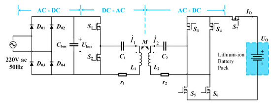
Figure 1.
The main circuit schematic of asymmetric WPT system for lithium-ion battery charging.
Class-E and class-D inverters usually serve as high-frequency inverters in the transmitter of WPT systems to drive the transmitting coil in medium- and low-power wireless charging devices because of their high transfer efficiency and simple structure. However, the operating state of Class-E inverter is seriously affected by the coupling coefficient and the load variation [29]. In order to simplify the modeling of asymmetrical wireless charging system, Class-D inverter is chosen in this paper. Besides, the transfer efficiency of WPT system can be improved by replacing diodes with MOSFETs in synchronous rectifier.
The transmitter and the receiver adopt the Series-Series (SS) compensation structure, with compensating capacitances in series with coils in both transmitter and receiver. The SS compensation structure is often used in the design with a wide range of load variations [30], and the current source characteristics on the receiver make the SS structure suitable for lithium-ion battery charging [31]. In addition, for WPT system with symmetric transmitter and receiver, the input impedance of the system at resonant frequency will not contain reactance for pure resistant load [32], which is convenient for comparison with the asymmetric WPT system.
Circuit theory and fundamental harmonic analysis is suitable for modeling the WPT system and acquiring the steady state characteristics [18]. The whole system can be simplified to an equivalent circuit model as shown in Figure 2. Here, , and represent fundamental harmonic phasors of output square wave of class-D inverter, transmitting coil current and receiving coil current, respectively. Li, Ci, ri (i = 1, 2) denote coil inductance, resistance and compensating capacitance of transmitter and receiver, respectively. k and M are coupling coefficient and mutual inductance, with the relationship . f represents the operating frequency, and ω = 2πf is the operating angle frequency. RE is the equivalent resistance of the receiver, which can be represented by the output load RO as:
where, UO and IO denote the output voltage and output current as shown in Figure 1, respectively. Us is the root mean square (RMS) value of the AC fundamental waveform of output of class-D inverter, and can be expressed by the duty cycle D and the input voltage Ubus [33]:
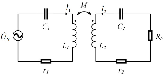
Figure 2.
The equivalent circuit model for asymmetric WPT system.
According to Kirchhoff’s voltage law the following equations can be obtained:
Here, and represent the impedance of transmitter and receiver, respectively.
According to (3) the expression of output power P can be achieved as follows:
For a WPT system with a symmetric transmitter and receiver, expression (4) of the output power will be simplified when operating at the resonant frequency, so that the output power characteristic of the system is very intuitive. In addition, for the symmetric case, when the coupling coefficient is relatively large the output power of WPT system will display a splitting phenomenon, that is, there will be two peak values of the power versus operating frequency [25]. The two peaks of output power will be equal and meet the maximum power principle [26]. However, due to the limitations of the lithium-ion battery pack size, the coil parameters of the transmitter and the receiver will be inconsistent. Moreover, the zero-voltage operation state of class-D inverter will also lead to the inconsistency of the resonant frequencies of the transmitter and the receiver. The power expression (4) will be more complicated because of the asymmetry of the transmitter and receiver. Hence, in the following section the output characteristics of asymmetric WPT system will be analyzed, and the variation law will be compared to that of the symmetric case.
3. Analysis of Maximum Output Power of Asymmetric WPT System
3.1. Output Power for Symmetric Cases
The output power characteristics of a symmetric WPT system are obtained first in order that a direct comparison can be conducted. For symmetric cases, the parameters in Figure 2 are chosen as: L1 = L2 = L = 700 μH, C1 = C2 = C = 1.72 nF, , f0 = ω0/2π = 145 kHz, r2 = 3 Ω, r1 = r2 + RE = R, V, so that the output power expression (4) can be simplified to (5):
Referring to the operating frequency range of the Qi standard [34], the output power curves of symmetric WPT system versus different RE values are obtained in a certain frequency range according to the (5), as shown in Figure 3. When the coupling coefficient k is relatively large, the curve of the output power will have two equal peaks, which means the frequency splitting phenomenon occurs. The maxima of output power are 73.58 W for Figure 3a and 45.88 W for Figure 3b, respectively. The corresponding frequencies are the splitting frequencies. The derivative of (5) versus ω helps obtain the critical coupling coefficient ks [26]:
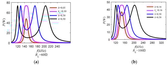
Figure 3.
Output power curves of symmetric WPT system versus different RE values. (a) RE = 60 Ω; (b) RE = 100 Ω.
The left-hand side of (6) comprises two four-order polynomials, so the corresponding splitting angle frequencies can be achieved through (7) and (8):
where Q = ω0L/R is the quality factor corresponding to R. Then, the possible real solution to (7) is:
and to (8):
Hence, we can conclude that when both real solutions of (8) exist, the symmetric WPT will display the frequency splitting phenomenon. At each splitting frequency the output power reaches the peak value expressed as ; otherwise, (8) has no real solution so the output power will have only one peak. According to the discriminant of (8), the critical coupling coefficient ks can be obtained:
When k > ks is satisfied, (8) has two real solutions and the frequency splitting phenomenon occurs; otherwise, there will be only one output power maximum. From (11) we can see that the relationship between and meets the two-order polynomial, as shown in Figure 4. When Q = 0.707, ks arrives at its peak of 1. According to (9) and (10) the splitting frequencies over certain range of k and RE can be plotted as Figure 5. The splitting frequencies is exactly the values where the output power reaches its peaks in Figure 3; when k is smaller than ks the frequency corresponding to the maximum output power is close to the resonant frequency f0. Moreover, the values of ks are the same as those in Figure 3.
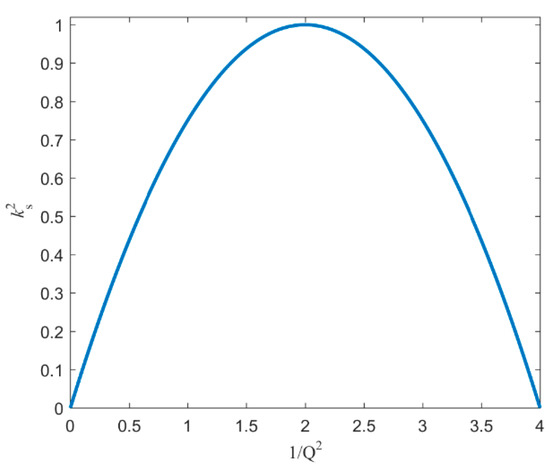
Figure 4.
Relationship between and .
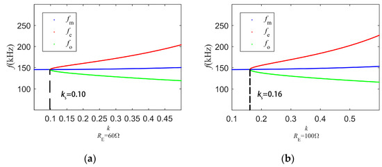
Figure 5.
Splitting frequencies over a certain range of k and RE. (a) RE = 60 Ω; (b) RE = 100 Ω.
Pmax over a certain range of k and RE is presented in Figure 6, which is consistent with the maximum value in Figure 3. It can be seen that Pmax is not affected by k when frequency splitting phenomenon occurs; otherwise, Pmax becomes larger with increasing k when k is smaller than ks. Besides, the larger the value of RE is, the smaller Pmax will be for the considered values of RE, which is also consistent with Figure 3.
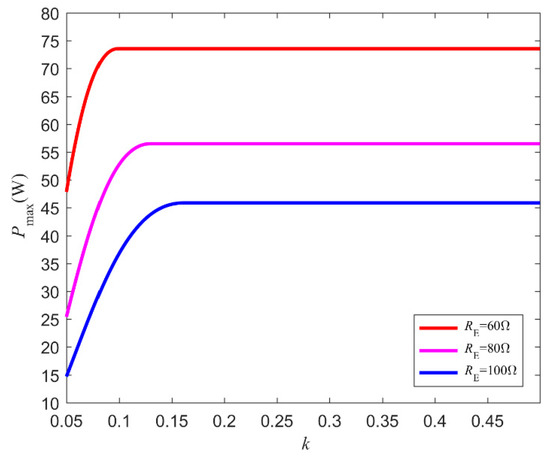
Figure 6.
Pmax over a certain range of k and RE.
Besides, we consider the input impedance of symmetric WPT system, which can be expressed as follows:
Substituting ω in (12) with the solutions to (10) leads to the result that the imaginary part of the input impedance Im(Zin) equals to zero. Since the condition Im(Zin) = 0 corresponds to the bifurcation phenomenon which is about the system stabilization [26,32], for symmetric WPT system the maximum output power can be obtained through bifurcation analysis. It is notable that the other solution of Im(Zin) = 0, f = f0, is not identical to the result of (10).
3.2. Output Power for Asymmetric Cases
3.2.1. The Case where ω1 = ω2
Here we consider the case in which ω1 = ω2 is satisfied in the asymmetric WPT system. This means the coil inductance of transmitter and receiver differ from that of receiver. And (3) can be expressed as follows:
where R2 = r2 + RE. Similar to the symmetric case, the derivative of (13) versus ω is needed for further analysis of maximum output power and the critical coupling coefficient for frequency splitting phenomenon, but the result will be more complicated. When the condition L1/L2 = r1/R2 is kept, the derivative is consistent with (6) except that Q = ω0L1/r1 is altered [26]. However, the maximum output power is changed to when the frequency splitting phenomenon occurs in this case. Figure 7 presents the curves of output power when L1/L2 = r1/R2. Here we have: L1 = 700 μH, L2 = 5.13 μH, C1 = 1.72 nF, C2 = 235 nF, , f0 = ω0/2π = 145 kHz, r2 = 0.05 Ω, V, and the same Q as Figure 3. As shown in Figure 7 the values of the coupling coefficient ks remain the same as those in Figure 3 due to the same Q, while the output power becomes different owing to asymmetry of transmitter and receiver, specifically the value of r1 and R2. Here, the maxima of output power are 68.89W for Figure 7a and 44.12 W for Figure 7b, respectively, compared to 73.58 W and 45.88 W for Figure 3.
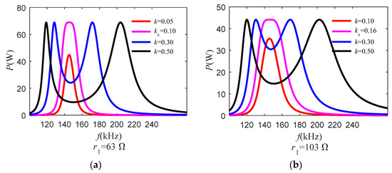
Figure 7.
The curves of output power when L1/L2 = r1/R2. (a) r1 = 63 Ω; (b) r1 = 103 Ω.
Considering the general case where L1/L2 ≠ r1/R2, derivative of (13) leads to an eight-order equation about ω:
where:
Note that Q1 = ω1L1/r1 and Q2 = ω2L2/R2 stand for quality factors of transmitter and receiver, respectively. The coefficients α, β and γ consist of given system parameters. In [28] numerical solutions to (15) are yielded. Subsequently, we can follow the approach proposed by Lodovico Ferrari [35,36] to solve (15) and obtain exact solutions. Since there is no three-order component about u contained in (14), (16) with two quadratic polynomials can be used to express (14):
Here, the coefficients b1, c1 and c2 are determined as follows [36]:
Hence, the possible real solutions to (16) can be presented as follows:
From (18) we can conclude that when all the three solutions in (18) exist, the asymmetric WPT system meets frequency splitting phenomenon; otherwise, if (16) has only one real solution, the output power will have only one peak. What’s more, from the solving process of Lodovico Ferrari [36] we can derive that when (19) is met, the intermediate variable y in (17) will have three real solutions leading to three disparate real solutions to (16):
Inequality (19) helps unveil the value of the critical coupling coefficient ks for frequency splitting phenomenon. According to (13) the output power curves of asymmetric WPT system versus different RE values are obtained in a certain frequency range, as shown in Figure 8. Here, the parameters are selected as: L1 = 700 μH, L2 = 5.13 μH, C1 = 1.72 nF, C2 = 235 nF, , f0 = ω0/2π = 145 kHz, r2 = 0.05 Ω, r1 = 3 Ω, V. ks used in Figure 8 is obtained by (19). Similarly, frequency splitting phenomenon occurs when k is larger than ks. However, despite of the same resonant frequencies of transmitter and receiver, two peak values of output power are different as a result of the asymmetric value of r1 and R2. Note that this is different from the result from CMT where two identical peak values are guaranteed as long as the resonant frequencies are the same [16]. According to Figure 8 the values of maximum output power for different k are listed in Table 1 along with the corresponding frequencies denoted as fmax. Note that the value of fmax is close to the resonant frequency f0 when k is smaller than ks.
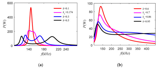
Figure 8.
Output power curves of asymmetric WPT system versus different RE values. (a) RE = 1 Ω; (b) RE = 5 Ω.

Table 1.
Maximum output power and the corresponding frequencies for asymmetric case when ω1 = ω2.
The results of (18) over a certain range of k and RE are presented in Figure 9. The values of the critical coupling coefficient are consistent with those in Figure 8. Moreover, the solutions to (18) are different values at k = ks for asymmetric WPT system here, while the solutions merge into the same value in symmetric cases as shown in Figure 5. As mentioned above, the two relative maxima of output power are not identical. Here the maximum output power will occur at the lowest frequency solution of (18), regardless of the value of k. When k is smaller than ks, the frequency corresponding to the maximum output power is close to the resonant frequency f0, like the symmetric case.
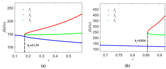
Figure 9.
Splitting frequencies over a certain range of k and RE for ω1 = ω2 asymmetric cases. (a) RE = 1 Ω; (b) RE = 5 Ω.
Substituting (18) into (13) yields the values of Pmax for different RE and k. The values of Pmax over a certain range of k and RE are presented in Figure 10. The results are the same as the peak values in Figure 8 and Table 1. Different from Figure 6, the values of Pmax increase with those of RE when k is small. This results from that fmax is close to the resonant frequency f0 as mentioned above, so the current source characteristic of SS structure is available [31]. As k becomes larger, fmax grows different from f0. As shown in Figure 10, smaller values of RE lead to higher Pmax when k is large enough. Moreover, for asymmetric WPT system here, Pmax becomes smaller as k increases all the time even k is larger than ks. This is because Pmax is related to k in the whole range of k in the case of an asymmetric WPT system.
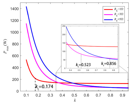
Figure 10.
Pmax over a certain range of k and RE for ω1 = ω2 asymmetric cases.
3.2.2. The case where ω1 ≠ ω2
Here, a specific asymmetric case in which ω1 ≠ ω2 will be discussed, namely that the resonant frequencies of transmitter and receiver are different. This case often happens where power converters are working at zero-voltage or zero-current state operation [27]. The expression of the output power (3) can be presented as:
Solving the derivative of (20) will result in the same form as (14)–(19), so the frequency splitting phenomenon and the critical coupling coefficient can be analyzed. According to (20) the output power curves of asymmetric WPT system versus different RE values can be obtained for the case ω1 > ω2 and ω1 < ω2 respectively, as shown in Figure 11. The parameters are selected as: r1 = 3 Ω, r2 = 0.05 Ω, V, L2 = 5.13 μH, C2 = 235 nF, , , f2 = ω2/2π = 145 kHz, L1 = 700 μH, C1 = 1.41 nF, f1 = ω1/2π = 160 kHz for ω1 > ω2; and L1 = 700 μH, C1 = 2.2 nF, f1 = ω1/2π = 128 kHz for ω1 < ω2. In Figure 11 there are two different relative maxima for output power when splitting phenomenon occurs; when k is smaller than ks, only one peak of output power exists. According to Figure 11 the values of maximum output power for different k are gathered in Table 2 along with the corresponding frequencies fmax.
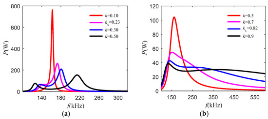
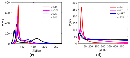
Figure 11.
Output power curves of asymmetric WPT system versus different RE values. (a) ω1 > ω2 and RE = 1 Ω; (b) ω1 > ω2 and RE = 5 Ω; (c) ω1 < ω2 and RE = 1 Ω; (d) ω1 < ω2 and RE = 5 Ω.
Table 2.
Maximum output power and the corresponding frequencies for asymmetric case when ω1 ≠ ω2.
The results of (18) for ω1 ≠ ω2 under a certain range of k and RE are shown in Figure 12. The values of ks are the same as those in Figure 11 and Table 2. It is notable that the values of ω1 and ω2 as well as RE affect the maximum values of output power. When ω1 > ω2 is satisfied and the value of RE is relatively low, the output power reaches the maximum value at the largest frequency solution regardless of the value of k as shown in Figure 12a; otherwise, the maximum output power corresponds to the lowest frequency solution as shown in Figure 12b–d.
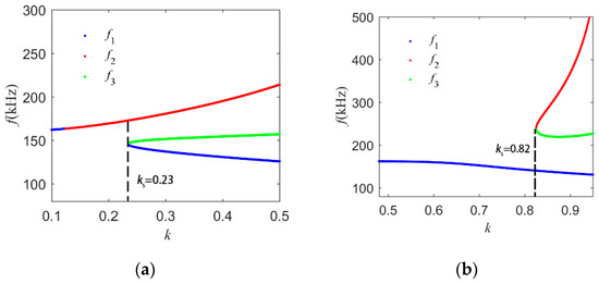
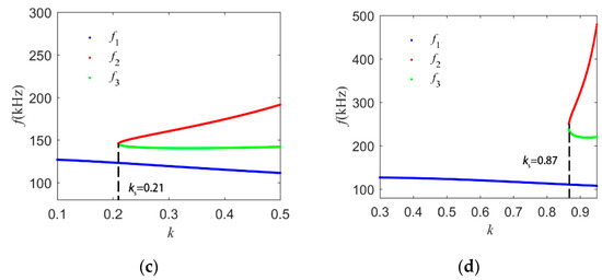
Figure 12.
Splitting frequencies under a certain range of k and RE for ω1 ≠ ω2. (a) ω1 > ω2 and RE = 1 Ω; (b) ω1 > ω2 and RE = 5 Ω; (c) ω1 < ω2 and RE = 1 Ω; (d) ω1 < ω2 and RE = 5 Ω.
Furthermore, when k < ks is met the frequency corresponding to the maximum output power becomes gradually close to the resonant frequency of the transmitter f1 as shown in Figure 12; this is also consistent with the values of fmax in Table 2. Besides, the variations of Pmax over a certain range of k and RE are similar to those in Figure 10 and will not be described in detail here.
The critical coupling coefficient ks for asymmetric WPT system can be obtained through (19) as mentioned before, but the results are not as intuitive as (11) in symmetric cases. Expansion of (19) can be expressed as an eight-order polynomial about k, which is more complicated than (11) but simpler than the result in [26]. With parameters chosen as: r1 = 3 Ω, L2 = 5.13 μH, C2 = 235 nF, L1 = 700 μH, C1 = 2.2 nF, the relationship between and is described over a certain range of Q2 for the case ω1 < ω2, as shown in Figure 13. With the help of MATLAB Curve Fitting Tool, the approximate relationship between and can be derived as follows:
where p1 = −0.1614; p2 = 0.8246; p3 = 0.004923. It indicates that the relationship between and can be described by two-order polynomial like (11) and Figure 4. In Figure 13, when ks approximately equals to 1; however, when there is no real solution for ks according to (19), which is quite different from the symmetric case.
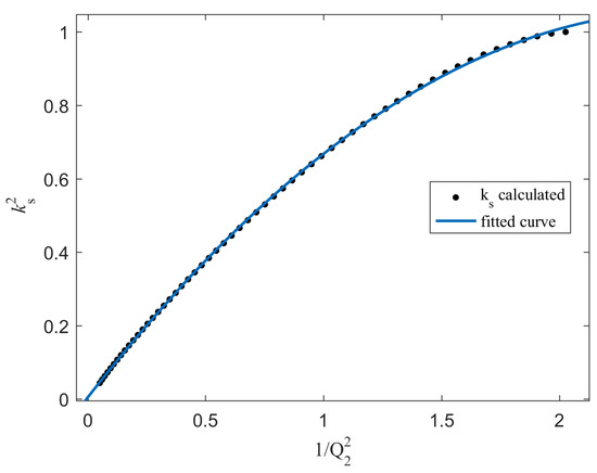
Figure 13.
Relationship between and obtained by MATLAB Curve Fitting Tool. The corresponding fitting results are as follows: SSE: 0.0005878; R-square: 0.9999; Adjusted R-square: 0.9999; RMSE: 0.003299.
Consider the input impedance of asymmetric WPT system at frequencies of (18). Substitute (18) into the expression of Zin (22), then the imaginary part of Zin Im(Zin) can be obtained in Figure 14 using parameters for the case ω1 < ω2. In Figure 14, Im(Zin) is close to zero at the frequency corresponding to the maximum output power when k is relatively low; however, as the value of k becomes larger, Im(Zin) are not close to zero at all splitting frequencies, which means that the solutions to Im(Zin) = 0 is not suitable to assess the peak output power in the asymmetric case:
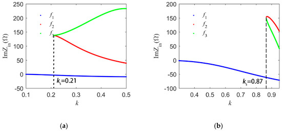
Figure 14.
The imaginary part of Zin at splitting frequencies for the case ω1 < ω2. (a) RE = 1 Ω; (b) RE = 5 Ω.
4. Experimental Validation
4.1. Prototype Description
The main circuit of our experimental prototype is shown in Figure 1. An 18 V lithium-ion battery pack for portable power tools was chosen as the load of the receiver. The receiving coil is designed considering the limitation of the load’s original configuration, while the transmitting coil should be properly designed so that the magnetic field is strong enough. Hence, an asymmetric transmitter and receiver are adopted in the prototype. The specific structures of the transmitting and receiving coils are presented in Figure 15. The transmitting coil has four layers, each of which comprises 14-turn 16-strand 0.12 mm-diameter Litz wire. Its outer radius is 4.8 cm and inner is 3.4 cm. The receiving coil has single layer, which includes 5-turn 90-strand 0.12-diameter Litz wire. Its outer radius is 3.9 cm and inner is 3 cm. Besides, ferrite core is added for both transmitter and receiver for shielding. The inductances of coils as well as the parasitic resistances are gathered in Table 3. When the two coils are placed on parallel plane with a vertical displacement of 12 mm and axially aligned, the measured coupling coefficient is 0.41.
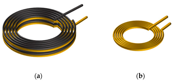
Figure 15.
Schematics of asymmetric transmitting and receiving coil. (a) transmitting coil. (b) receiving coil.
Table 3.
Main parameters for the experimental prototype.
The Class-D inverter in the transmitter comprises a pair of N-MOSFETs (STD8NM50N). The synchronous full-bridge rectifier in the receiver includes a pair of N-MOSFETs (Si7414DN) and a pair of P-MOSFETs (Si7415DN). The main parameters of the prototype are shown in Table 3, which are similar to the case ω1 < ω2 mentioned in the preceding section.
4.2. Experimental Results
The implementation of prototype is shown in Figure 16. Here, A is the lithium-ion battery pack for portable power tools. B is the receiver circuit board. C denotes the transmitter circuit board. D denotes the transmitting coil. E is the receiving coil. F is a transparent board to separate the transmitter and receiver.
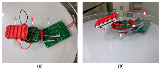
Figure 16.
The implementation of prototype. (a) Top view; (b) Front view.
In order to simplify the analysis, the operating frequency is fixed to 145 kHz, which is the same as the resonant frequency of the receiver. According to (22), the input impedance of the asymmetric WPT system is inductive. For a fixed-frequency WPT system the frequency splitting phenomenon causes a drastic variation of output power. To deal with the frequency splitting phenomenon additional implementation should be adopted, such as adaptive impedance matching and frequency tracking, thus system complexity increases [37,38]. In this paper the parameters of prototype are considered carefully to avoid frequency splitting. A static asymmetric WPT experiment is conducted to verify the analytical results and offers proper power to the load. Consider that output current is 3 A which is suitable for the charging, so the value of equivalent output load is RO = 6 Ω when the output voltage is 18 V. According to Equations (1), (15), (17) and (19), the value of critical coupling coefficient ks can be obtained as 0.84. The selected value of coupling coefficient 0.41 is smaller than ks, so the frequency splitting phenomenon will not occur.
Figure 17 presents the currents of transmitting coil and receiving coil and the output voltage of class-D inverter. In Figure 17 the current of transmitting coil lags the output voltage of class-D inverter properly so that zero-voltage operation is achieved [27]. The phase between the fundamental wave of the two currents is 90 degrees when WPT system operates at the receiver’s resonant frequency [19,27], but the actual waveforms are affected by the harmonics from the class-D inverter and the synchronous full-bridge rectifier, and distortions exist.
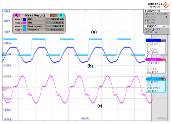
Figure 17.
Waveforms of the prototype. (a) the output voltage of class-D inverter; (b) the current of transmitting coil; (c) the current of receiving coil.
Figure 18 exhibits the charging voltage and charging current of the load. The RMS of voltage is slightly lower than 18 V, and the RMS of current is 3.15 A, so the output power is about 56 W. For a coupling coefficient of 0.41, the calculation result according to the preceding analysis should be 61.4 W, which is not completely the same as the experiment result. Nonetheless, considering the influence of harmonics distortions and the power cost caused by switches in the inverter, the result is relatively precise, and the design can provide proper output power for the 18 V lithium-ion battery pack. Note that with the same output load resistance the coupling coefficient corresponding to the highest output power should be 0.51. For safe charging of lithium-ion battery pack, a lower coupling coefficient is chosen, and adequate output power is offered. The experimental results still support the proposed analysis.
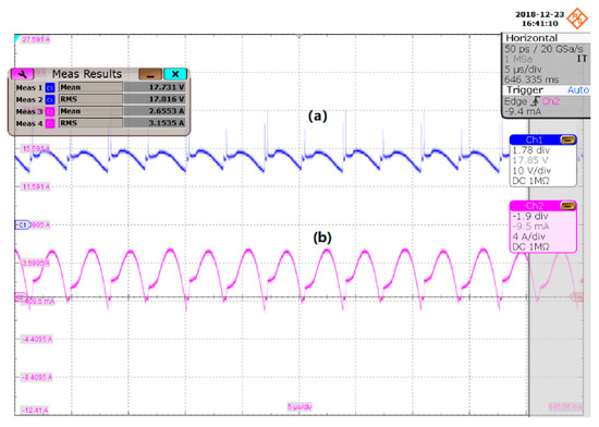
Figure 18.
Output waveforms. (a) output voltage; (b) output current.
5. Discussion and Conclusions
This paper focuses on WPT systems with asymmetric transmitters and receivers. The output power characteristics are analyzed in detail. The frequency splitting phenomenon for asymmetric WPT systems is discussed theoretically and crucial characteristics are concluded. Cases for different resonant conditions are elaborated for a comprehensive understanding of the asymmetric WPT system. The influence of the coupling coefficient and the value of the load on the output power is different compared with preceding symmetric WPT systems. Hence, the analysis in this paper helps better understand the output power characteristics of practical WPT devices which possess diverse sizes and configurations. The experimental results verify that the proposed analysis is feasible to guide the design of asymmetric WPT system, and the scheme can be adapted to various WPT applications, especially to common lithium-ion battery charging products.
Author Contributions
Z.G. established the model, analyzed the characteristics of the model, conducted the experiment and wrote the article. B.Z. and D.Q. guided and revised the paper.
Funding
This project was supported by the Key Program of National Natural Science Foundation of China (Grant No. 51437005) and National Natural Science Foundation of China (Grant No. 51677074).
Conflicts of Interest
The authors declare no conflict of interest.
References
- Hui, S.Y.R.; Zhong, W.; Lee, C.K. A critical review of recent progress in mid-range wireless power transfer. IEEE Trans. Power Electron. 2014, 29, 4500–4511. [Google Scholar] [CrossRef]
- Triviño-Cabrera, A.; Sánchez, J. A Review on the Fundamentals and Practical Implementation Details of Strongly Coupled Magnetic Resonant Technology for Wireless Power Transfer. Energies 2018, 11, 2844. [Google Scholar] [CrossRef]
- Hsieh, Y.C.; Lin, Z.R.; Chen, M.C.; Hsieh, H.C.; Liu, Y.C.; Chiu, H.J. High-Efficiency Wireless Power Transfer System for Electric Vehicle Applications. IEEE Trans. Circuits Syst. II: Express Briefs 2017, 64, 942–946. [Google Scholar] [CrossRef]
- Zhang, W.; White, J.C.; Abraham, A.M.; Mi, C.C. Loosely coupled transformer structure and interoperability study for EV wireless charging systems. IEEE Trans. Power Electron. 2015, 30, 6356–6367. [Google Scholar] [CrossRef]
- Tang, S.C.; Lun, T.L.T.; Guo, Z.; Kwok, K.W.; McDannold, N.J. Intermediate range wireless power transfer with segmented coil transmitters for implantable heart pumps. IEEE Trans. Power Electron. 2017, 32, 3844–3857. [Google Scholar] [CrossRef]
- Ahn, D.; Ghovanloo, M. Optimal Design of Wireless Power Transmission Links for Millimeter-Sized Biomedical Implants. IEEE Trans. Biomed. Circuits Syst. 2016, 10, 125–137. [Google Scholar] [CrossRef]
- Bana, V.; Kerber, M.; Anderson, G.; Rockway, J.D.; Phipps, A. Underwater wireless power transfer for maritime applications. In Proceedings of the 2015 Wireless Power Transfer Conference (WPTC), Boulder, CO, USA, 13–15 May 2015. [Google Scholar] [CrossRef]
- Yan, Z.; Zhang, Y.; Song, B.; Zhang, K.; Kan, T.; Mi, C. An LCC-P Compensated Wireless Power Transfer System with a Constant Current Output and Reduced Receiver Size. Energies 2019, 12, 172. [Google Scholar] [CrossRef]
- Zhou, J.; Zhang, B.; Xiao, W.; Qiu, D.; Chen, Y. Nonlinear Parity-Time-Symmetric Model for Constant Efficiency Wireless Power Transfer: Application to a Drone-in-Flight Wireless Charging Platform. IEEE Trans. Ind. Electron. 2019, 66, 4097–4107. [Google Scholar] [CrossRef]
- Song, C.; Kim, H.; Kim, Y.; Kim, D.; Jeong, S.; Cho, Y.; Kim, J. EMI Reduction Methods in Wireless Power Transfer System for Drone Electrical Charger Using Tightly Coupled Three-Phase Resonant Magnetic Field. IEEE Trans. Ind. Electron. 2018, 65, 6839–6849. [Google Scholar] [CrossRef]
- Nam, I.I.; Dougal, R.A.; Santi, E. Novel unity-gain frequency tracking control of series–series resonant converter to improve efficiency and receiver positioning flexibility in wireless charging of portable electronics. IEEE Trans. Ind. Appl. 2015, 51, 385–397. [Google Scholar] [CrossRef]
- Liu, H.; Huang, X.; Tan, L.; Guo, J.; Wang, W.; Yan, C.; Xu, C. Dynamic Wireless Charging for Inspection Robots Based on Decentralized Energy Pickup Structure. IEEE Trans. Ind. Inform. 2018, 14, 1786–1797. [Google Scholar] [CrossRef]
- Kurs, A.; Kaealis, A.; Moffatt, R.; Joannopoulos, J.D.; Fisher, P.; Soljacic, M. Wireless power transfer via strongly coupled magnetic resonances. Science 2007, 317, 83–86. [Google Scholar] [CrossRef]
- Chen, C.; Zhou, H.; Deng, Q.; Luo, X. Nonlinear modeling and feedback control of WPT system via magnetic resonant coupling considering continuous dynamic tuning. In Proceedings of the 2017 Chinese Automation Congress (CAC), Jinan, China, 20–22 October 2017. [Google Scholar] [CrossRef]
- Li, H.; Wang, K.; Huang, L.; Chen, W.; Yang, X. Dynamic modeling based on coupled modes for wireless power transfer systems. IEEE Trans. Power Electron. 2015, 30, 6245–6253. [Google Scholar] [CrossRef]
- Niu, W.Q.; Gu, W.; Chu, J.X.; Shen, A.D. Coupled-mode analysis of frequency splitting phenomena in CPT systems. Electron. Lett. 2012, 48, 723–724. [Google Scholar] [CrossRef]
- Sample, A.P.; Meyer, D.T.; Smith, J.R. Analysis, experimental results, and range adaptation of magnetically coupled resonators for wireless power transfer. IEEE Trans. Ind. Electron. 2011, 58, 544–554. [Google Scholar] [CrossRef]
- Li, Z.; Zhu, C.; Jiang, J.; Song, K.; Wei, G. A 3-kW wireless power transfer system for sightseeing car supercapacitor charge. IEEE Trans. Power Electron. 2017, 32, 3301–3316. [Google Scholar] [CrossRef]
- Li, H.; Yang, X.; Wang, K.; Dong, X. Study on efficiency maximization design principles for wireless power transfer system using magnetic resonant coupling. In Proceedings of the 2013 ECCE Asia Downunder (ECCE Asia), Melbourne, VIC, Australia, 3–6 June 2013. [Google Scholar] [CrossRef]
- Hui, S.Y. Planar wireless charging technology for portable electronic products and Qi. Proc. IEEE 2013, 101, 1290–1301. [Google Scholar] [CrossRef]
- Kim, J.; Kim, D.-H.; Park, Y.-J. Analysis of Capacitive Impedance Matching Networks for Simultaneous Wireless Power Transfer to Multiple Devices. IEEE Trans. Ind. Electron. 2015, 62, 2807–2813. [Google Scholar] [CrossRef]
- Kim, J.; Kim, D.H.; Park, Y.J. Free-positioning wireless power transfer to multiple devices using a planar transmitting coil and switchable impedance matching networks. IEEE Trans. Microw. Theory Tech. 2016, 64, 3714–3722. [Google Scholar] [CrossRef]
- Kurs, A.; Moffatt, R.; Soljačić, M. Simultaneous mid-range power transfer to multiple devices. Appl. Phys. Lett. 2010, 96, 044102. [Google Scholar] [CrossRef]
- Li, Y.; Song, K.; Li, Z.; Jiang, J.; Zhu, C. Optimal Efficiency Tracking Control Scheme Based on Power Stabilization for a Wireless Power Transfer System with Multiple Receivers. Energies 2018, 11, 1232. [Google Scholar] [CrossRef]
- Huang, R.; Zhang, B.; Qiu, D.; Zhang, Y. Frequency splitting phenomena of magnetic resonant coupling wireless power transfer. IEEE Trans. Magn. 2014, 50, 1–4. [Google Scholar] [CrossRef]
- Niu, W.Q.; Chu, J.X.; Gu, W.; Shen, A.D. Exact analysis of frequency splitting phenomena of contactless power transfer systems. IEEE Trans. Circuits Syst. I: Regul. Pap. 2013, 60, 1670–1677. [Google Scholar] [CrossRef]
- Li, H.; Li, J.; Wang, K.; Chen, W.; Yang, X. A maximum efficiency point tracking control scheme for wireless power transfer systems using magnetic resonant coupling. IEEE Trans. Power Electron. 2015, 30, 3998–4008. [Google Scholar] [CrossRef]
- Sîrbu, I.G.; Mandache, L. On the power transfer in series-series magnetically coupled circuits with non-matched natural frequencies. In Proceedings of the 2016 Applied and Theoretical Electricity (ICATE), Craiova, Romania, 6–8 October 2016. [Google Scholar] [CrossRef]
- Li, X.; Li, Y.P.; Tsui, C.Y.; Ki, W.H. Wireless Power Transfer System With ∑∆-Modulated Transmission Power and Fast Load Response for Implantable Medical Devices. IEEE Trans. Circuits Syst. II: Express Briefs 2017, 64, 279–283. [Google Scholar] [CrossRef]
- Cai, H.; Shi, L.; Li, Y. Harmonic-based phase-shifted control of inductively coupled power transfer. IEEE Trans. Power Electron. 2014, 29, 594–602. [Google Scholar] [CrossRef]
- Diekhans, T.; De Doncker, R.W. A dual-side controlled inductive power transfer system optimized for large coupling factor variations and partial load. IEEE Trans. Power Electron. 2015, 30, 6320–6328. [Google Scholar] [CrossRef]
- Wang, C.S.; Covic, G.A.; Stielau, O.H. Power transfer capability and bifurcation phenomena of loosely coupled inductive power transfer systems. IEEE Trans. Ind. Electron. 2004, 51, 148–157. [Google Scholar] [CrossRef]
- Jiang, Y.; Zhang, B. High-Power Fractional-Order Capacitor With 1 < α < 2 Based on Power Converter. IEEE Trans. Ind. Electron. 2018, 65, 3157–3164. [Google Scholar] [CrossRef]
- Wireless Power Consortium-Qi specification 1.2.3. Available online: https://www.wirelesspowerconsortium.com/knowledge-base/specifications/download-the-qi-specifications.html (accessed on 26 January 2017).
- Jan, G. Mathematics: From the Birth of Numbers; Norton: New York, NY, USA, 1997; pp. 320–324. [Google Scholar]
- Quartic Equation. Available online: http://mathworld.wolfram.com/QuarticEquation.html (accessed on 2 March 2019).
- Lyu, Y.L.; Meng, F.Y.; Yang, G.H.; Che, B.J.; Wu, Q.; Sun, L.; Li, J.L.W. A method of using nonidentical resonant coils for frequency splitting elimination in wireless power transfer. IEEE Trans. Power Electron. 2015, 30, 6097–6107. [Google Scholar] [CrossRef]
- Schmidt, C.; Buchholz, M. Extended Discussion on Non-Identical Planar Resonant Coils for Frequency Splitting Elimination. In Wireless Power Transfer Systems. Proceedings of the Smart SysTech 2016; European Conference on Smart Objects, Systems and Technologies, Duisburg, Germany, 7–8 June 2016; VDE: Berlin, Germany, 2016. [Google Scholar]


© 2019 by the authors. Licensee MDPI, Basel, Switzerland. This article is an open access article distributed under the terms and conditions of the Creative Commons Attribution (CC BY) license (http://creativecommons.org/licenses/by/4.0/).