Article

Study on Design and Vibration Reduction Optimization of High Starting Torque Induction Motor

School of Electrical & Electronics Engineering, Harbin University of Science and Technology, Harbin 150080, China
*
Author to whom correspondence should be addressed.
Energies 2019, 12(7), 1263; https://doi.org/10.3390/en12071263
Submission received: 25 February 2019 / Revised: 29 March 2019 / Accepted: 29 March 2019 / Published: 2 April 2019

Abstract

:
Induction motors are widely used in various applications. This study considers a Y2-200L2-6 three-phase induction motor. Its starting torque was improved by combining the characteristics and design method of a star-delta hybrid connection winding, which can meet the demand of the motor for oil fields. Meanwhile the electromagnetic vibration and optimization of vibration reduction were studied based on the improved motor. The electromagnetic performance of the improved motor was calculated, and the electromagnetic force distribution of the motor was obtained based on the results of the transient magnetic field. Based on the calculation results of the electromagnetic force, a transient dynamic analysis of the motor was performed, and the electromagnetic vibration displacement curve of the motor was obtained. The experimental results of the vibration were compared with the finite element simulation results to verify the validity of the calculation method. The optimal design scheme of the stator winding was proposed based on the characteristics of the winding connection. The radial electromagnetic force and electromagnetic vibration displacement of the motor before and after winding optimization were compared, and the feasibility of the optimization scheme in reducing electromagnetic vibration was verified.

1. Introduction

Induction motors are widely used in various applications owing to their simple structure, low production cost, convenient use and maintenance, reliable operation, and other characteristics. Furthermore, induction motors have good characteristics and high efficiency. They can operate at nearly constant speed from no-load to full-load, which is suitable for most industrial and agricultural production applications. Although induction motors have many advantages, they still have some shortcomings in specific situations, such as oil fields. A high-power motor is often used in a low-load operation to satisfy the requirements of high starting torque, which results in a great waste of energy.
To improve the operation performance of a motor, it is effective to change the winding connection mode. The characteristics and advantages of a star-delta hybrid connection winding and its influence on motor efficiency have been presented in references [1,2]. The study [3] states that the use of star-delta hybrid connection in three-phase windings can reduce copper consumption and harmonic components. In a previous study [4], by analyzing the phase separation, turn ratio, and winding arrangement of a low-harmonic motor with star-delta hybrid connection windings, a simple phase separation method for windings with odd slots per pole was proposed. In the study [5], by using a slot phasor star graph, the amplitude and angle of the fundamental wave and the harmonics of the star connection part and the delta connection part at different slot numbers per pole per phase were analyzed, and the inherent law of the combination of the two parts was determined. In the study [6], a brushless doubly-fed machine with a star-delta hybrid connection of rotor windings was designed, which confirmed that it can effectively improve the actual utilization of rotor slot conductors. In this paper, the traditional three-phase asynchronous motor winding connection was change to a star-delta hybrid connection. In addition, the stator core was properly lengthened. The improved motor achieved a large starting torque with a smaller frame size, and the production cost of the motor reduced effectively.
When the motor is running, the electromagnetic force, electromagnetic vibration, and electromagnetic noise will inevitably be generated. Therefore, the study of electromagnetic vibration of motors is very important. Researchers at home and abroad have extensively studied the electromagnetic force of motors and variations on the law of electromagnetic vibration [7,8,9,10]. The study [11,12] analysed the problems of structural dynamics under stochastic excitation. A stochastic perturbation-based numerical solution to the Duffing equation originating from the Taylor expansion of the general order was proposed in the study [13] to analyze the vibrations of a micro-resonator with random damping coefficient adopted as a Gaussian input parameter. A previous study [14] calculated the electromagnetic force of a permanent magnet synchronous motor using the finite element method, and determined the law of magnetic field harmonics with low order and high amplitude. Dr. Yang Haodong of Zhejiang University studied the electromagnetic vibration of the permanent magnet synchronous motor with fractional slot winding, and proposed a method to eliminate the low-order radial force by adding a compensation current, so as to restrain the vibration of the motor [15]. The study [16] proposed that a dual skew rotor structure can effectively eliminate odd-order electromagnetic force and weaken even-order radial electromagnetic force and effectively reduce vibration. In some studies, a reasonable slot-pole combination and chute were used to calculate and study the vibration reduction of motors [17,18,19]. The study [20] considered the switched reluctance motor as the research subject, including the influence of salient pole structure and thickness of core yoke on the motor modal. In the study [21], the influence of the quality and stiffness of laminated cores and windings on natural frequency and modal shape was quantitatively analyzed by means of finite element analysis and experimental measurements to obtain effective material properties. Some scholars have proposed the use of slotting on the stator or rotor to reduce electromagnetic vibration in permanent magnet motors [22,23]. The magnetostrictive effect of a silicon steel sheet on motor vibration was studied [24]. A study on permanent magnet motors showed that the current harmonics near the switching frequency have a significant impact on electromagnetic vibration [25]. In some studies, the electromagnetic force of an electric motor was obtained through the finite element method or an applied algorithm, and the variation of electromagnetic vibration was explored [26,27,28,29]. Among them, a new structure for a vibration reduction rotor was proposed on the basis of electromagnetic force analysis in reference [26]. In many studies of electromagnetic vibration, many scholars have achieved vibration reduction of the motors by changing the structure of the stator and rotor. In this paper, the harmonic magnetic potential of motor windings is affected by the change of turn ratio and number of parallel branches, and the improved effect of vibration reduction can be found. Thus, the complex process problems caused by the change in stator and rotor structure are avoided.
In this paper, the improved induction motor is called a prototype in the following sections. The magnetic field performance of the motor before and after the improvement is compared by using the finite element method, and the validity of variation of electromagnetic vibration calculated using the finite element analysis is verified through experiments. Based on the prototype, the turn ratio and branch number of the winding are optimized again. By comparing the electromagnetic force amplitude and vibration displacement curves of the motor before and after stator winding, the optimization method is proved to be effective.

2. Prototype Parameters and Magnetic Field Calculation

2.1. Prototype Parameters

This study considers a Y2-200L2-6 three-phase induction motor as the research object. As the star-delta hybrid connection winding has the advantage of enhancing fundamental waves and weakening harmonics compared with the traditional 60° phase-band winding, in order to satisfy the requirement of high starting torque, the stator winding of the original motor is changed from double-layer overlapping winding to star-delta hybrid connection winding. The winding connection schematic diagram is shown in Figure 1, in which the number of turns in the star connection part is nine and the number of turns in the delta connection part is 16, and the wire diameter of the winding should be changed appropriately to match the stator current. Thus, the original wire diameter of 1~1.12 and 1~1.18 can be changed to 2~1.5 and 2~1.12. The basic parameters of the improved motor (prototype) are listed in Table 1.

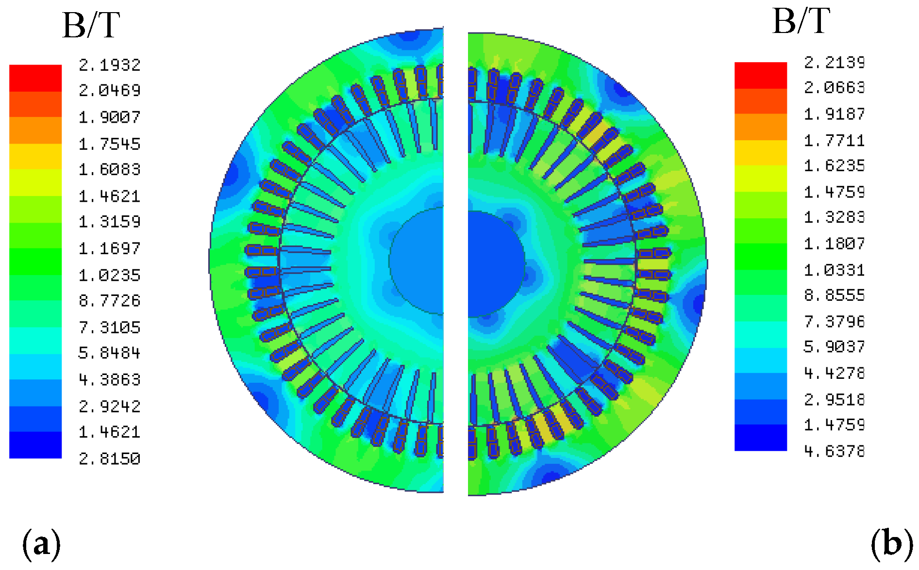
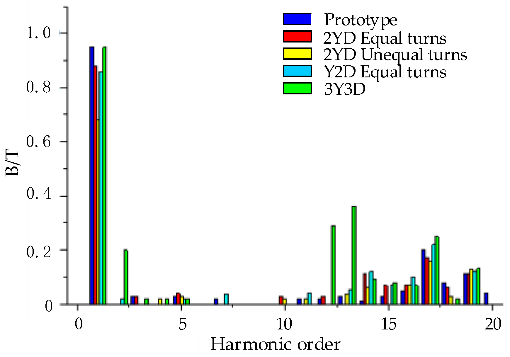
2.2. Calculation of the Magnetic Field and Starting Performance

The two-dimensional model is used for the finite element calculation of the magnetic field. It avoids the complex three-dimensional finite element model and a lot of computing time. Furthermore, the distribution of electromagnetic force in the axial direction is similar, so the electromagnetic force calculated based on the transient electromagnetic field of the two-dimensional model can be loaded into the three-dimensional model of the transient dynamic calculation of the motor, which also greatly improves computational efficiency.
The two-dimensional model of the motor was employed, and the fundamental equation describing the space and time variations of the vector potential over the region of analysis has the following form [30,31]:
D : x ( 1 μ A Z x ) + y ( 1 μ A Z y ) = σ A Z t J Z Γ 1 : A Z = 0
where D is the region of analysis; Γ 1 is the outside circumference of the stator and inside circumferential of the rotor (the Dirichlet boundary conditions); J z is the current density; σ is the conductivity of the conductors; A z is the magnetic vector potential; μ is the permeability of the material.
The magnetic field calculation model of the motor is shown in Figure 2. The simulation calculation was performed under the rated load condition, and the obtained magnetic field results are shown in Figure 3. The air gap flux density waveform and its harmonic analysis before and after the improvement are compared in Figure 4 and Figure 5, respectively. As shown in Figure 4 and Figure 5, in addition to the fundamental wave amplitude increases, the fifth and seventh harmonics of the air gap flux density were effectively weakened. The air gap flux density waveform was improved, and the waveform was close to the sine wave.
The starting performance of the motor was analyzed, and the starting torque and the starting current multiple of the motor before and after improvement were compared, which is shown in Table 2. The starting torque of the prototype was significantly increased, which satisfies the requirements of high starting torque motor. Simultaneously, the starting current also increased, hence, it is necessary to change the winding diameter appropriately so that the motor can also operate safely and steadily.

3. Calculation and Analysis of Electromagnetic Vibration

3.1. Time-Domain Characteristics of Electromagnetic Force Waves

As the radial electromagnetic force has a significant influence on the vibration, the normal electromagnetic force is ignored. According to the Maxwell stress equation, the radial electromagnetic force per unit area in the air-gap is expressed as follow [32]:
P n ( θ , t ) = b n 2 ( θ , t ) 2 μ 0
where b n ( θ , t ) is the instantaneous value of the radial air-gap flux density; μ 0 is the air permeability; P n ( θ , t ) is the radial electromagnetic force per unit area in the air-gap.
After calculating the transient magnetic field of the motor, according to the Maxwell stress tensor method, the radial force density acting on the stator can be obtained as shown in Formula (3).
f n = 1 μ 0 ( B n 2 B t 2 2 )
According to the results of the finite element calculation, Figure 6 shows the curve of radial electromagnetic force density varying with time at a point. From the figure, it can be observed that the radial electromagnetic force density of the prototype has high amplitude and evident fluctuation. To analyze the frequency components of the radial electromagnetic force, the frequency spectrum of it at a point was analyzed and is shown in Figure 7. The amplitude at 0 Hz is a constant component, whereas the amplitude at 100 Hz is generated by the fundamental magnetic field.

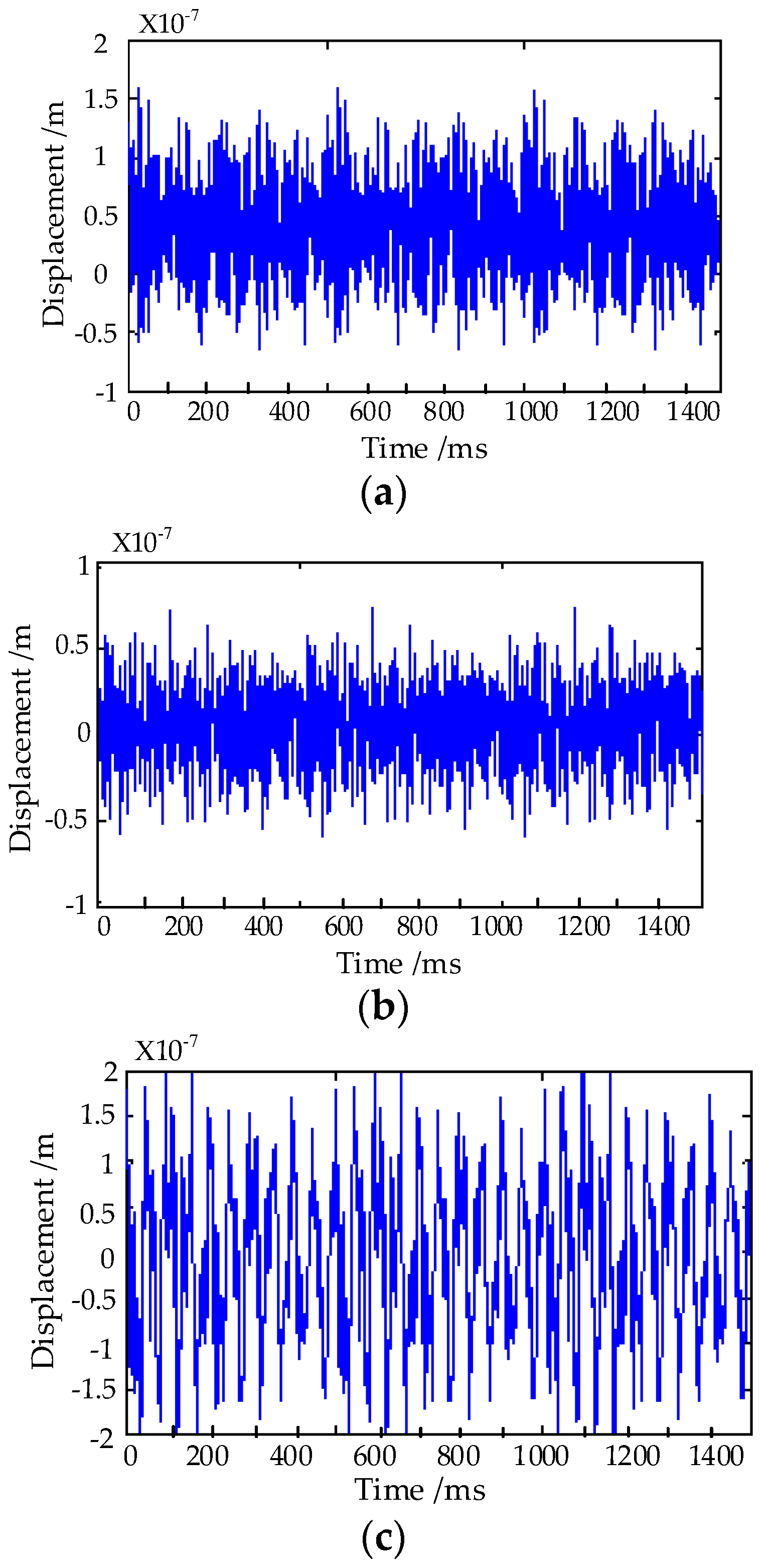
3.2. Time-Domain Calculation and Analysis of Electromagnetic Vibration

Through the calculation of transient electromagnetic field, the radial electromagnetic force density of the motor can be obtained. Five points are uniformly extracted near one stator tooth in the air gap. As the prototype has 54 stator teeth, the radial electromagnetic force density of 270 points can be extracted. The radial electromagnetic force density is multiplied by the corresponding surface area of the stator teeth, which is equal to the radial electromagnetic force, and the radial electromagnetic force is loaded onto the corresponding position of the stator teeth.
Setting the displacement of the four bases of the motor to zero, the transient dynamic calculation model of the motor was established as shown in Figure 8. Sweep meshing was applied to establish the finite element model which is composed of hexahedral elements. As the motor structure is complex, the whole motor was split into several geometries for sweep meshing. The scattered geometries were connected as a whole using the technology of MPC “binding”, so that the amount of elements and total computing time were greatly reduced, meanwhile, the continuity of the displacement DOF (degrees of freedom) of the elements at splitting position can be guaranteed. The point A on the casing was the reference point, the vibration displacement curves of the point A in the three directions X, Y, and Z were obtained by calculation and are shown in Figure 9.

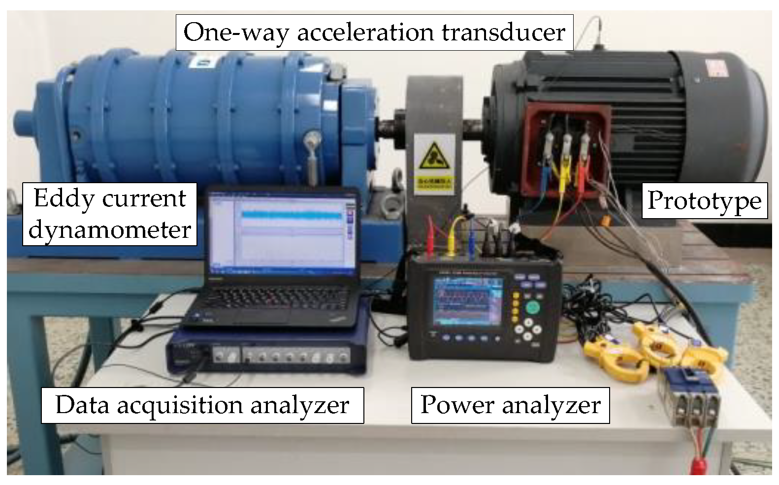
3.3. Comparison of Calculation and Experiment of Electromagnetic Vibration

To verify the validity of the electromagnetic vibration displacement obtained by finite element simulation, the vibration test of the prototype was performed, and the Y-direction vibration displacement of the motor was the research object. Figure 10 shows the laboratory testing platform and the testing instrument. The AVANT MI-7008 dynamic data acquisition analyzer was used for data analysis in vibration testing. The signal acquisition was based on a high-sensitivity ICP-type one-way acceleration sensor. By controlling the dynamometer, the motor operated in a stable state, and the radial vibration displacement signal of the motor was measured by using an one-way acceleration sensor. The time-domain and frequency-domain curves of vibration displacement were obtained using the data analysis instrument.
The simulation results of vibration displacement were compared with the measured results in the time domain and frequency domain, respectively, as shown in Figure 11 and Figure 12. By contrast, it was observed that the measured displacement amplitude was larger, because the finite element simulation did not involve the influence of other factors, such as mechanical vibration, test platform instrument, and motor fixing, hence, the displacement amplitude obtained by simulation was smaller than the test value. The displacement curve of the prototype was analyzed by using the frequency spectrum. According to the comparison results, it can be observed that the characteristic frequencies were 625 Hz and 825 Hz, respectively, except for double frequency. The simulation results are consistent with the test results. In addition, a certain vibration frequency that is less that 50Hz occurs can be found in the test result, and these frequencies are smaller in the simulation. The influence of the imbalance of the test platform and instrument was not considered in the simulation. Therefore, it may have lead to a slight difference between simulation and test.

4. The Optimal Design for the Stator Winding of Vibration Reduction

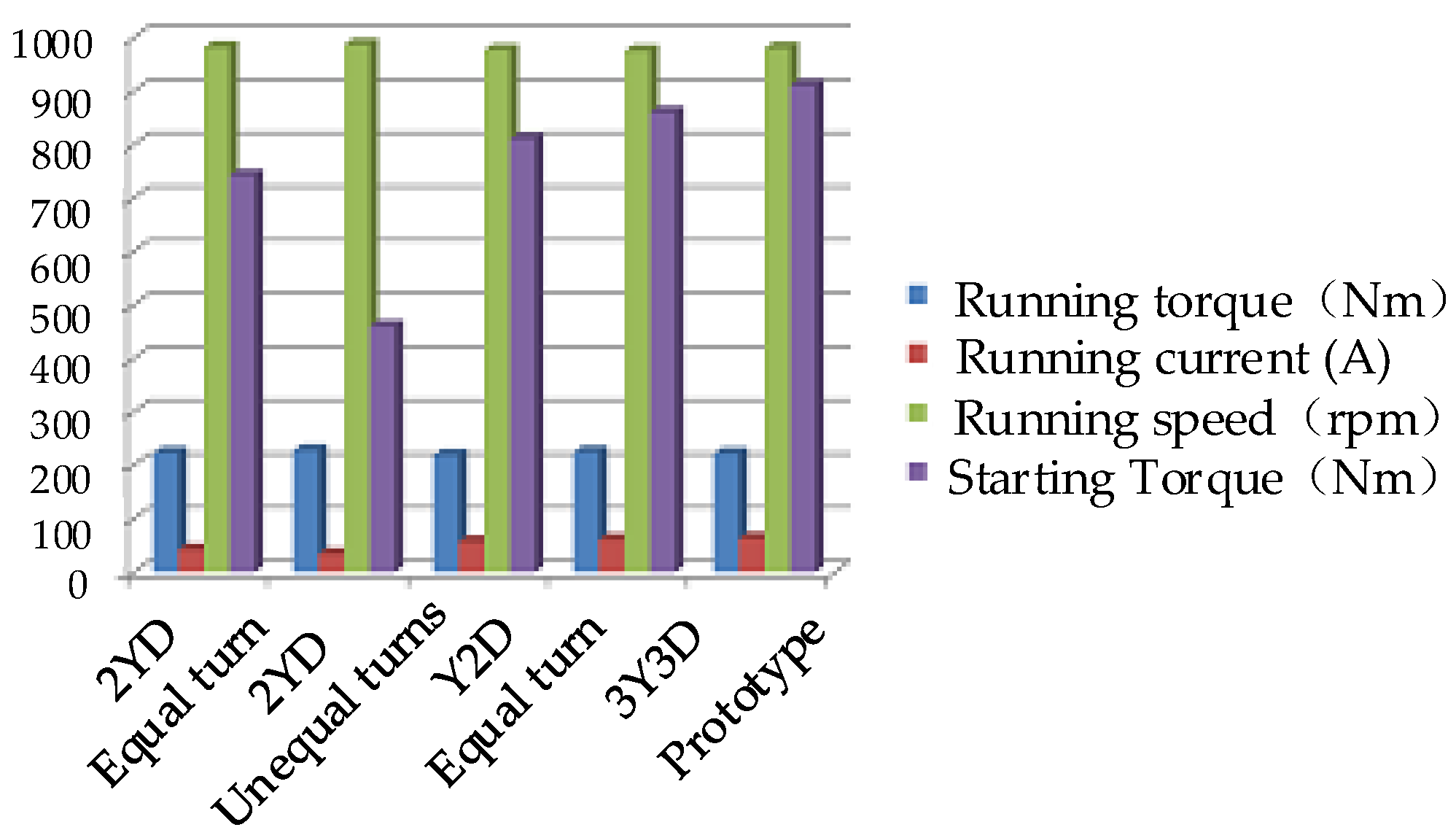
4.1. Winding Optimization Scheme

According to the characteristics of star-delta hybrid connection windings, the prototype can be further optimized by changing the turn ratio and number of branches, so as to obtain a greater effect on reducing vibration. The magnetic field of the star-delta hybrid connection winding motor is composed of the star connection part and the delta connection part. The expressions of fundamental and sub-harmonic synthetics are as follows [33]:
f 1 ( θ s , t ) = 1.35 P ( N Φ Υ K d p 1 Υ + N Φ Δ 3 K d p 1 Δ ) I cos ( θ s ω t ) f ν ( θ s , t ) = 1.35 P ( N Φ Υ K d p ν Υ + ( 1 ) k N Φ Δ 3 K d p ν Δ ) I cos ( ν θ s ω t )
where N Φ Υ , N Φ Δ is the number of turns in series per phase for the star connected winding and delta connected winding, respectively; K d p ν Υ , K d p ν Δ is the coefficient of star connected winding and delta connected winding. The expression is as follows:
N Φ Υ = p q Υ Z Υ a Υ N Φ Δ = p q Δ Z Δ a Δ
K d p ν Υ = sin ν q Υ α 2 q Υ sin ν α 2 K d p ν Δ = sin ν q Δ α 2 q Δ sin ν α 2
By substituting Equations (5) and (6) into Equation (4), it can be deduced that the fundamental wave of the winding, the harmonic distribution coefficient and the equivalent turns per phase in series are:
k d 1 = sin q Υ α 2 + N Δ a Υ 3 N Υ a Δ sin q Δ α 2 ( q + a Υ N Δ q Δ 3 a Δ N Υ ) sin α 2 k d ν = sin ν q Υ α 2 + ( 1 ) k ( N Δ a Υ 3 N Υ a Δ ) sin ν q Δ α 2 ( q Υ + q Δ N Δ a Υ 3 N Υ a Δ ) sin ν α 2 N Φ Υ Δ = p S ( q Υ N Υ a Υ + q Δ N Δ 3 a Δ )
where S is the coefficient; the single layer winding takes 1 and double layer winding takes 2; N Υ , N Δ are the number of winding turns of the star connection and delta connection, respectively; a Υ , a Δ are the number of branches of the star and delta windings, respectively; p is the number of pole pairs; and q Υ , q Δ are the number of slots per pole per phase for the star connection and delta connection, respectively.
When q is even:
q Δ = q Υ = q 2
When q is odd:
q Δ = ( q ± 1 ) 2 q Υ = ( q 1 ) 2
It can be seen that in the case of a Υ = a Δ = a and N Δ = 3 N y , the total ampere-turns of the star junction and the angle junction are equal. Hence, the fifth and seventh harmonics can be significantly weakened or even eliminated. However, for high voltage motors, because the number of turns per coil is relatively small, it is often difficult to ensure N Δ = 3 N y in practical design, especially for q Υ q Δ , and it is even more difficult to keep the number of turns per slot equal. Therefore, the winding design scheme can comprehensively should be considered comprehensively based on request, and select the appropriate turn ratio and number of branches.
The stator slots of the prototype are 54, and the number of slots per pole per phase is three, so three types of star-delta hybrid connection windings, namely a y = 1 , a Δ = 2 (Y2D, for short); a y = 2 , a Δ = 1 (2YD, for short); and a y = a Δ = 3 (3Y3D, for short) can be selected. The turn ratios N Δ = 3 N y and N Δ = N y are selected as the main optimization schemes in this paper because the main purpose of the selection is to eliminate the fifth and seventh harmonics.
In conclusion, the alternative design options are as follows: Y2D, 2YD, 3Y3D, and the winding connections are shown in Figure 1, Figure 13 and Figure 14, respectively, including equal turns and unequal turns. In this paper, four optimization schemes were studied, that is, 2YD (equal turns), 2YD (unequal turns), Y2D (equal turns) and 3Y3D. Furthermore, the motor operated at the rated load.
The performances of the motor operating under the rated load with different winding connection schemes are shown in Figure 15, and the harmonic analysis of air gap magnetic flux density is shown in Figure 16. By comparing these figures, it was found that the winding connection of 2YD (equal turns) was adopted, the better operating performance and starting performance could be ensured, and the amplitude of various orders of harmonics of the air gap flux density were effectively weakened. Therefore, 2YD (equal turns) was chosen as the final optimization schemes to design the stator winding.

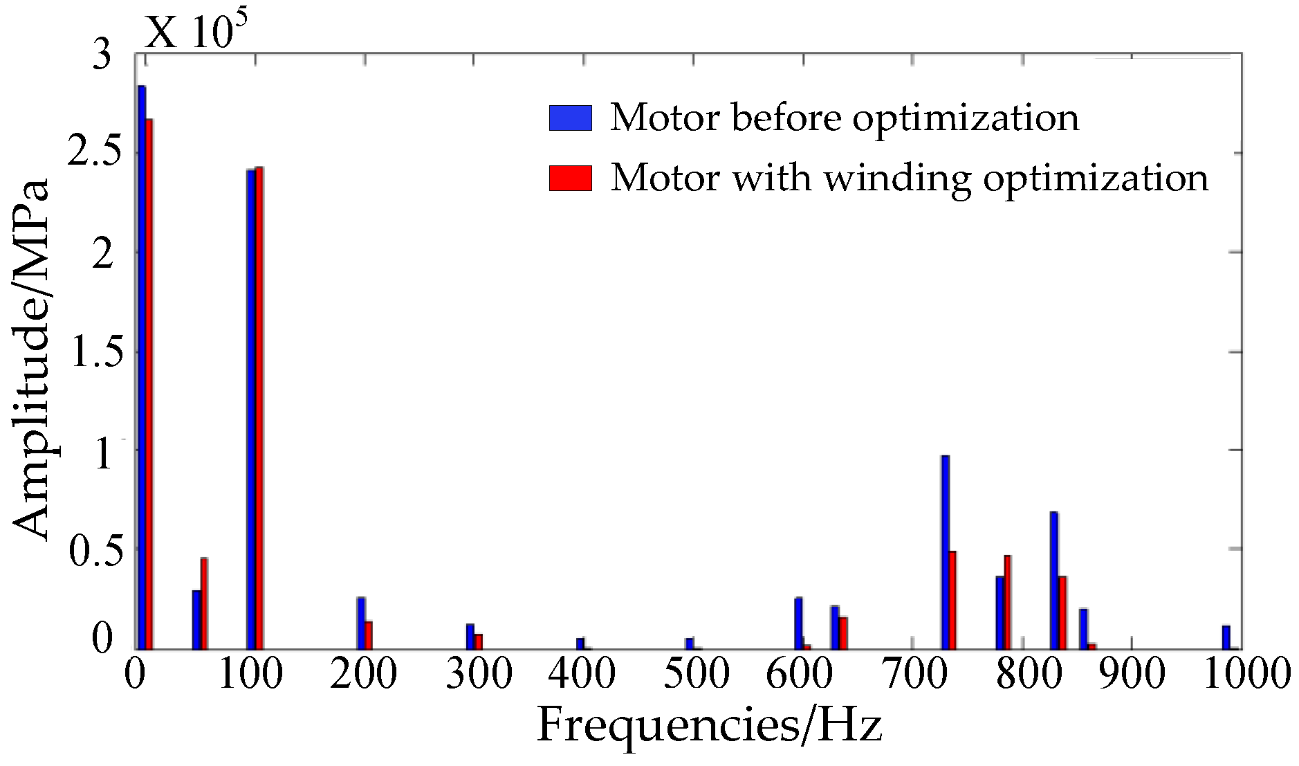
4.2. Electromagnetic Vibration Before and After Winding Optimization

The calculation method of the radial electromagnetic force density is the same as that described above. Figure 17 shows the time-varying curve of the radial electromagnetic force density at a certain point selected on the air gap near any tooth of the motor stator before and after winding optimization. From the figure, it can be observed that the radial electromagnetic force density before winding optimization had a high amplitude and evident fluctuation. After winding optimization, the radial electromagnetic force density amplitude of the motor decreased, and the electromagnetic force fluctuation became smaller. To analyze the frequency components of the radial electromagnetic force compared with on winding optimization, the spectral analysis of the radial electromagnetic force density at the point was performed as shown in Figure 18. The amplitude at 0 Hz is a constant component and it is slightly decreased after optimization. The amplitude at 100 Hz is generated by the fundamental magnetic field, and it was nearly unchanged before and after optimization. For the higher-frequency components, the radial electromagnetic force density amplitudes of the motor after winding optimization were significantly reduced.
According to the results of the electromagnetic force calculation, the transient dynamics of the motor after winding optimization was calculated. Similarly, considering the point A on the motor casing as the reference point, the vibration displacement curves of the motor after the winding optimization in the X, Y and Z directions are shown in Figure 19. By the comparison of the displacement curves before and after the winding optimization, it can be observed that the radial vibration displacement of the motor after winding optimization was significantly lower than that of the prototype, and the optimized design was achieved.

5. Conclusions

In this paper, the stator winding connection and core of a traditional three-phase induction motor were appropriately improved in order to meet the requirements of special working conditions in oil fields. The improved motor not only saves production cost, but also satisfies the demand of high starting torque, which can avoid wasting energy. In this study, the magnetic field, electromagnetic force and electromagnetic vibration of the prototype were calculated using the finite element method, and the vibration experiments verified the correctness of the simulation results. Furthermore, the optimal winding design scheme for vibration reduction was presented by analyzing various winding connection modes. Combined with the above, the conclusions obtained are as follows:
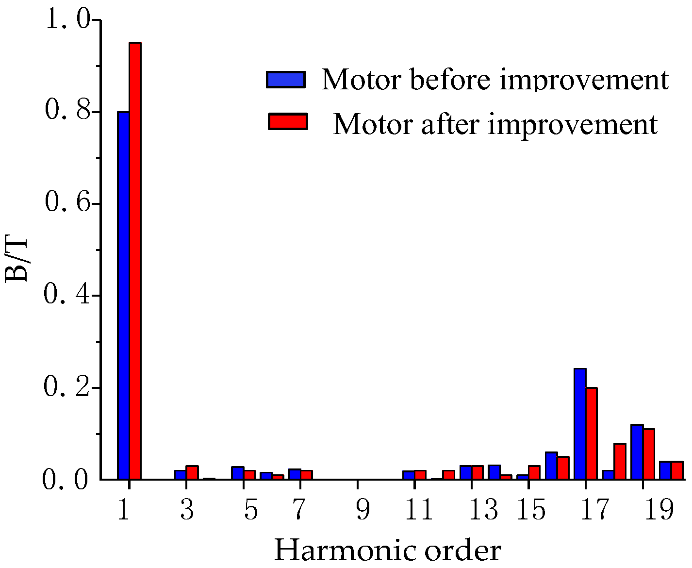
  • The starting torque of the improved motor has been significantly increased, and the air gap flux density waveform was effectively improved, that is, the amplitude of the fundamental wave increased, and the fifth- and seventh-order harmonics were effectively weakened.
  • By analyzing the radial vibration displacement of the prototype in the time domain and frequency domain, it can be observed that the simulation results are consistent with the experimental results, which confirms the reliability of the calculation method proposed in this paper. Because the influence of mechanical vibration and other factors were not considered in the simulation process, the simulation result was slightly smaller than the experimental value.
  • In this paper, the optimal design scheme for vibration reduction windings was proposed. The adopted stator winding design of 2YD (equal turns) can ensure that the starting performance of the motor is not significantly affected, meanwhile, the motor has better magnetic field characteristics and operation performance.
  • After winding optimization, the amplitude and fluctuation of the electromagnetic force of the motor were evidently reduced, and the corresponding vibration displacement of the motor was evidently reduced, especially in the Y direction, which means the object of optimization design was reached. In addition, the radial vibration displacement was larger than the axial vibration displacement.
  • This paper designs a high-start torque induction motor for oil field operations, which meets the requirements of high starting torque and low load operation. At the same time, the vibration reduction optimization method proposed in this paper can provide a reference for the vibration reduction design of other types of induction motors.

Author Contributions

Y.X. supervised the whole process; C.P. implemented the simulation; Z.L. checked the paper format.

Funding

This work was supported by The Heilongjiang Province Science Fund for Distinguished Young Scholars (JC2016010).

Conflicts of Interest

The authors declare no conflict of interest.

References

  1. Wang, J. Research of Δ-Y connected low harmonic winding. Electr. Mach. Technol. 1996, 17–41. [Google Scholar]
  2. Zhang, C.; Yang, G.; Meng, S. Efficiency of three-phase induction motors with a connected stator winding. J. Huazhong Univ. Sci. Technol. 1983, 11, 91–96. (In Chinese) [Google Scholar]
  3. Auinger, H.; Fei, Y. Three-phase winding uses star-delta hybrid connection to reduce copper consumption and harmonic components. Medium Small Mot. 1984, 58–65. Available online: http://kns.cnki.net/KCMS/detail/detail.aspx?dbcode=CJFQ&dbname=CJFD7984&filename=ZXXD198403018&uid=WEEvREdxOWJmbC9oM1NjYkZCbDdrdW1OMEorK2tRNWZlVlBBR1VUZkhGd2w=$R1yZ0H6jyaa0en3RxVUd8df-oHi7XMMDo7mtKT6mSmEvTuk11l2gFA!!&v=MzAxMjRhckt4RnRYTXJJOUViSVI4ZVgxTHV4WVM3RGgxVDNxVHJXTTFGckNVUkxPZlkrWnVGQ25sVTdyTVB6WFQ= (accessed on 2 April 2019).
  4. Zou, C. Three-phase star—Some key issues of triangular winding–theoretical design and manufacturing and repair practice. Mot. Technol. 1989, 11–14. [Google Scholar]
  5. Yang, Y. Harmonic analysis of star and triangular sinusoidal windings and its new type. Mot. Technol. 2009, 6–10. Available online: http://kns.cnki.net/KCMS/detail/detail.aspx?dbcode=CJFQ&dbname=CJFD2009&filename=DJIJ200901004&uid=WEEvREdxOWJmbC9oM1NjYkZCbDdrdW1OMEorK2tRNWZlVlBBR1VUZkhGd2w=$R1yZ0H6jyaa0en3RxVUd8df-oHi7XMMDo7mtKT6mSmEvTuk11l2gFA!!&v=MDEyNTh6UElTZkNaTEc0SHRqTXJvOUZZSVI4ZVgxTHV4WVM3RGgxVDNxVHJXTTFGckNVUkxPZlkrWnVGQ25sVnI= (accessed on 2 April 2019).
  6. Kan, C.; Xia, B.; Liu, Q.; Chen, P.; Li, H. Research on brushless doubly-fed machine with star-delta connection of rotor winding. Micromotor 2013, 46, 6–9. [Google Scholar]
  7. Yamazaki, K. Comparison of induction motor characteristics calculated from electromagnetic field and equivalent circuit determined by 3D FEM. IEEE Trans. Magn. 2000, 36, 1881–1885. [Google Scholar] [CrossRef]
  8. McDevitt, T.E.; Campbell, R.L.; Jenkins, D.M. An investigation of induction motor zeroth-order magnetic stresses, vibration and sound radiation. IEEE Trans. Magn. 2004, 40, 774–777. [Google Scholar] [CrossRef]
  9. He, H.; Liu, H. Radial electromagnetic radial force analysis in induction motors. Micromotors 2011, 44, 26–30. [Google Scholar]
  10. Lang, W.; Xiao, B.; Chong, D.; Yang, Z. Influence on vibration and noise of squirrel-cage induction machine with double skewed rotor for different slot combinations. IEEE Trans. Magn. 2016, 52, 8104404. [Google Scholar]
  11. Kapitaniak, T.; Bishop, S. A Dictionary of Nonlinear Dynamics; Wiley: Chichester, UK, 1999. [Google Scholar]
  12. Muscolino, G. Non-stationary pre-envelope covariances of non-classically damped systems. J. Sound Vib. 1988, 149, 107–123. [Google Scholar] [CrossRef]
  13. Kamiński, M.; Corigliano, A. Numerical solution of the Duffing equation with random coefficients. Meccanica 2015, 50, 1841–1853. [Google Scholar] [CrossRef] [Green Version]
  14. Han, X.; Li, S.; Mi, X. Research on radial magnetic force of permanent magnet synchronous motor supplied by sine wave. Adv. Technol. Electr. Eng. Energy 2016, 3, 1–5. [Google Scholar]
  15. Yang, H.; Chen, Y. Electromagnetic vibration analysis and suppression of permanent magnet synchronous motor with fractional slot combination. Proc. CSEE 2011, 3, 1–5. [Google Scholar]
  16. Toru, I.; Akatsu, K. Electromagnetic sorce acquisition distributed in electric motor to reduce vibration. IEEE Trans. Ind. Appl. 2016, 53, 1001–1008. [Google Scholar]
  17. Wang, D.; Zhu, C.; Fu, J. Electromagnetically excited vibration analysis for an asynchronous electrical machine with finite element method. J. Vib. Shock 2012, 31, 140–144. [Google Scholar]
  18. Dai, Y.; Cui, S.; Zhang, Q. Analysis on electromagnetic vibration/noise of induction motors for EV drives. Proc. CSEE 2012, 32, 89–97. [Google Scholar]
  19. Xie, Y.; Liu, H.; Lv, S.; Liu, H. Study on electromagnetic vibration of cage induction motor considering rotor chute. Proc. Chin. J. Electr. Eng. 2015, 35, 3952–3954. [Google Scholar]
  20. Xie, Y.; Liu, H. Study on the variation laws of electromagnetic vibration considered the skewed rotor in a squirrel-cage induction motor. Proc. CSEE 2015, 35, 3952–3954. [Google Scholar]
  21. Long, S.A.; Zhu, Z.Q.; Howe, D. Vibration behaviour of stators of switched reluctance motors. IEEE Proc. Electr. Power Appl. 2001, 148, 257–264. [Google Scholar] [CrossRef]
  22. Hwang, S.M.; Lee, H.J.; Kim, T.S.; Jung, Y.H.; Hong, J.P. The influence of electromagnetic force upon the noise of an IPM motor used in a compressor. IEEE Trans. Magn. 2006, 42, 3494–3496. [Google Scholar] [CrossRef]
  23. Zhang, R.; Wang, X.H.; Qiao, D.W.; Yang, Y.B. Reduction of exciting force wave for permanent magnet motors by teeth notching. Proc. CSEE 2010, 30, 103–108. [Google Scholar]
  24. Zang, X.; Xiu, H.; Yang, Y.; Wei, B. Vibration reduction of a switches reluctance motor using new rotor tooth with slot on each side. Proc. CSEE 2015, 35, 1508–1515. [Google Scholar]
  25. Yan, R.; Wu, Y.; Liu, W.; Zhang, X.; Duan, M. Influence of magmetostriction effect on induction motor vibration. Small Spec. Electr. Mach. 2016, 44, 27–29. [Google Scholar]
  26. Zuo, S.; Liu, X.; Yu, M.; Wu, X.; Zhang, G. Numerical prediction and analysis of electromagnetic vibration in permanent magnet synchronous motor. Trans. China Electrotech. Soc. 2017, 32, 159–167. [Google Scholar]
  27. Li, Y.; Liu, J.; Xia, J. Electromagnetically excited vibration calculation and analysis for a three-phase asynchronous motor with finite element method. J. Electr. Eng. 2015, 10, 30–33. [Google Scholar]
  28. Jang, I.S.; Ham, S.H.; Kim, W.H.; Jin, C.S.; Cho, S.Y. Method for analyzing vibrations due to electromagnetic force in electric motors. IEEE Trans. Magn. 2014, 50, 7007204. [Google Scholar] [CrossRef]
  29. Immovilli, F.; Bianchini, B.; Cocconcelli, M.; Bellini, A. Bearing fault model for induction motor with externally induced vibration. IEEE Trans. Ind. Electron. 2013, 60, 3408–3418. [Google Scholar] [CrossRef]
  30. Tang, Y. Electromagnetic Field in Electric Machine, 2nd ed.; Science Press: Beijing, China, 1998. [Google Scholar]
  31. Yan, D.; Liu, R.; Hu, M. Transient starting performance of squirrel cage induction motor with time-stepping FEM. Electr. Mach. Control 2003, 7, 177–181. [Google Scholar]
  32. Chen, Y.; Zhu, Z.; Ying, S. Analysis and Control of Motor Noise; Zhejiang University Press: Hangzhou, China, 1987. [Google Scholar]
  33. Wang, S.; Zhao, Z. Design of sinusoidal hard winding for high voltage asynchronous motors. Trans. China Electrotech. Soc. 2009, 24, 8–13. [Google Scholar]
Figure 1. The winding connection diagram of the prototype.
Energies 12 01263 g001
Figure 2. Calculation model of motor.
Energies 12 01263 g002
Figure 3. Distribution of flux density of motor before and after improvement: (a) motor before improvement; (b) motor after improvement.
Energies 12 01263 g003
Figure 4. Air gap flux density waveform of motor before and after improvement: (a) motor before improvement; (b) motor after improvement.
Energies 12 01263 g004
Figure 5. Each harmonic of the air gap flux density before and after improvement.
Energies 12 01263 g005
Figure 6. Curve of time-varying radial electromagnetic force density of the prototype.
Energies 12 01263 g006
Figure 7. Frequency spectrum analysis of radial electromagnetic force.
Energies 12 01263 g007
Figure 8. 3D finite element model of the motor for dynamic calculation.
Energies 12 01263 g008
Figure 9. Curves of the time-varied vibration displacement of point A: (a) X direction; (b) Y direction; (c) Z direction.
Energies 12 01263 g009
Figure 10. Vibration test platform.
Energies 12 01263 g010
Figure 11. Curves of the time-varied vibration displacement in the Y direction at point A on the motor shell: (a) simulation value; (b) experimental value.
Energies 12 01263 g011
Figure 12. Frequency spectrum of the vibration displacement in the Y direction at point A on the motor shell: (a) simulation value; (b) experimental value.
Energies 12 01263 g012
Figure 13. Winding connection diagram of 2YD ( a y = 2 , a Δ = 1 ).
Energies 12 01263 g013
Figure 14. Winding connection diagram of 3Y3D ( a y = a Δ = 3 ).
Energies 12 01263 g014
Figure 15. Performance comparison of each optimization scheme.
Energies 12 01263 g015
Figure 16. Harmonic comparison of air gap magnetic flux density with each optimization scheme.
Energies 12 01263 g016
Figure 17. The time-varying radial electromagnetic force before and after winding optimization.
Energies 12 01263 g017
Figure 18. Comparison of the frequency spectrum of the radial electromagnetic force.
Energies 12 01263 g018
Figure 19. Curves of the time-varied vibration displacement at point A of the motor with winding optimization: (a) X direction; (b) Y direction; (c) Z direction.
Energies 12 01263 g019
Table 1. Parameters of the prototype motor.
ParameterValueParameterValue
Rated power (kW)22Rated voltage (V)380
Power frequency (Hz)50Rated speed (rpm)980
Stator outer diameter (mm)327Stator inner diameter (mm)230
Number of stator slots54Number of rotor slots44
Air gap length (mm)0.5 Core height (mm)245
Table 2. Starting performance of the motor before and after improvement.
Starting PerformanceStarting Torque-Simulation Value /NmStarting Torque-Design Value/NmStarting Current Ratio Calculated Value
Motor before improvement5105306.34
Motor after improvement9239147.973

