An Analysis Model Combining Gamma-Type Stirling Engine and Power Converter

Abstract
:1. Introduction
2. Modeling
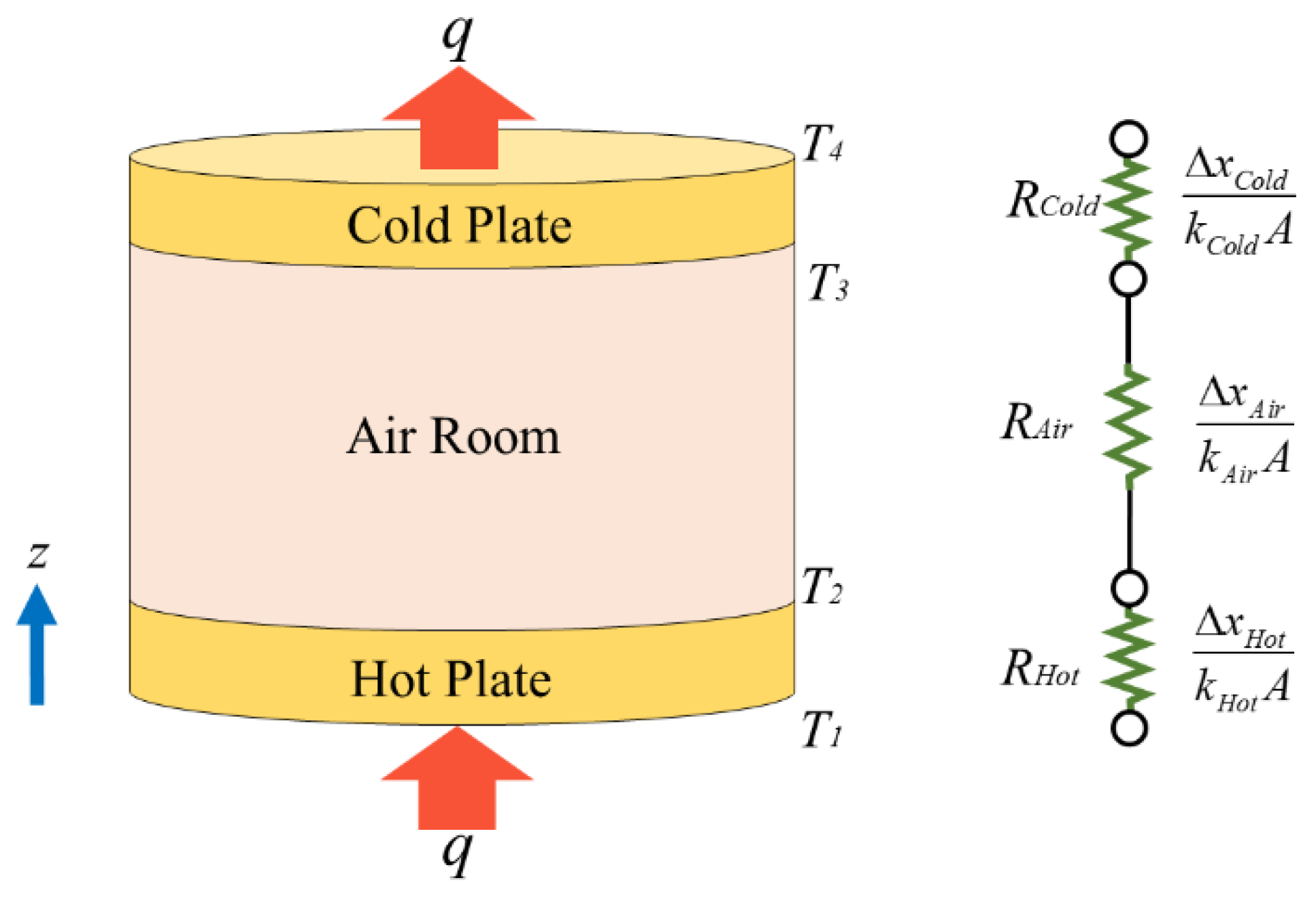
2.1. Heat Transfer
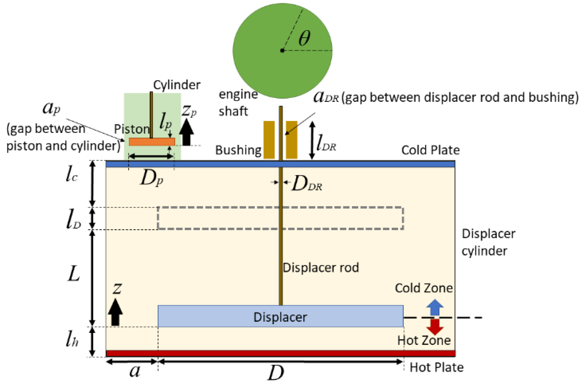
2.2. Kinematics
2.3. Gas Work
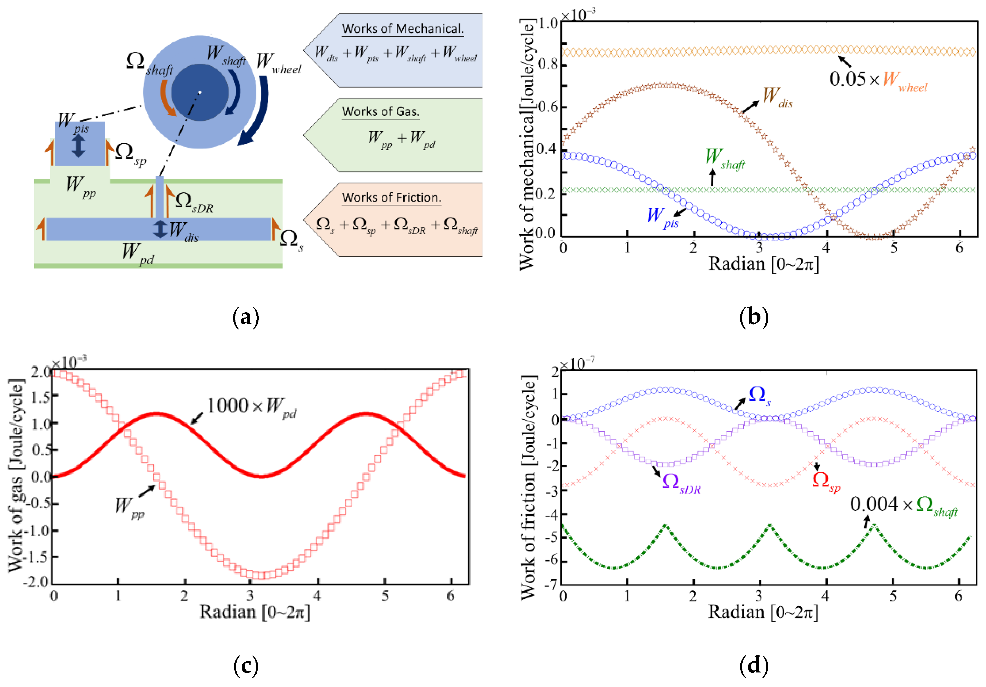
2.4. Mechanical Component Work
2.5. Friction Loss
2.6. Electrostatic Capacitance
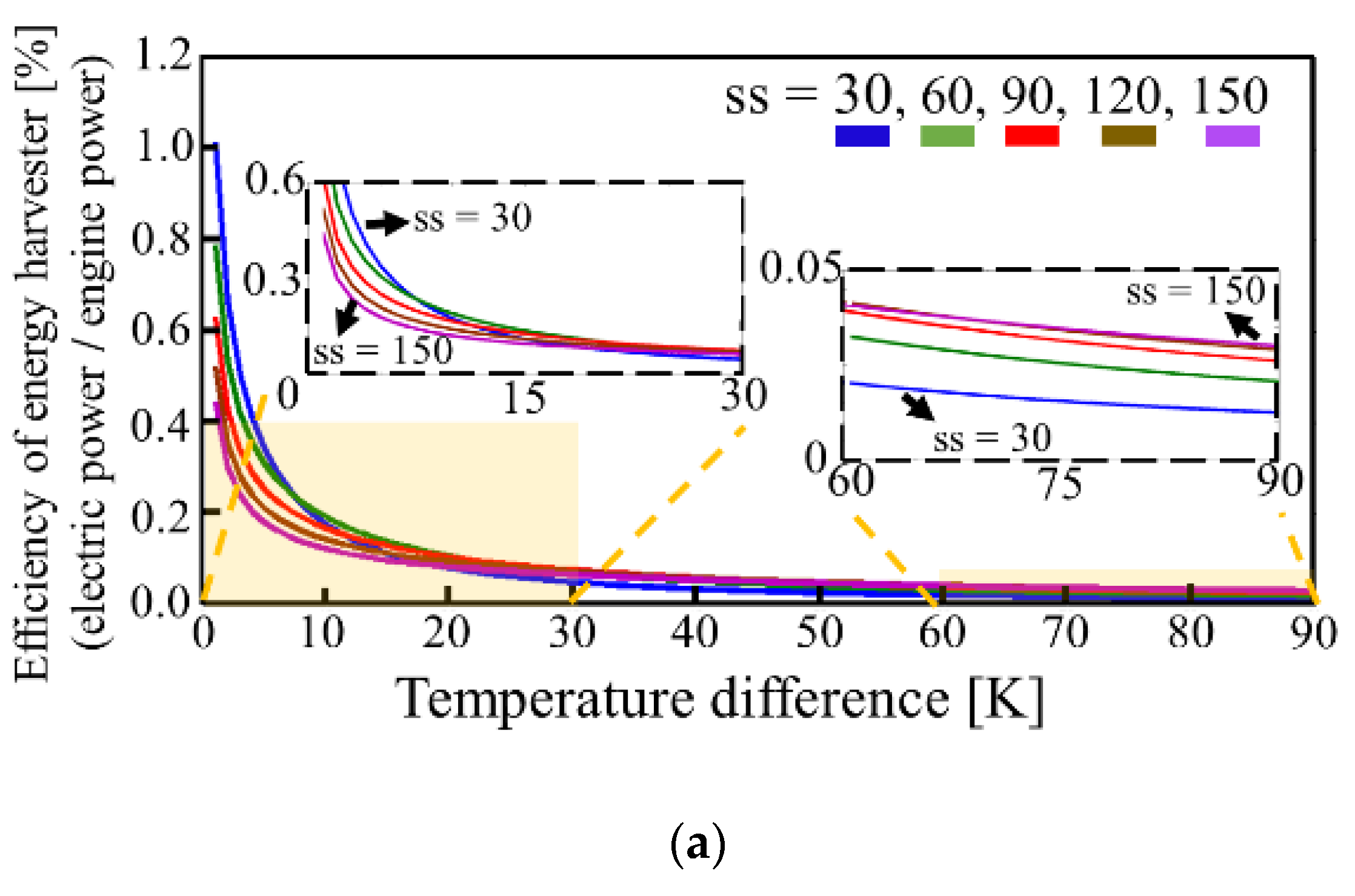
3. Result and Discussion
4. Conclusions
Funding
Conflicts of Interest
Appendix A

| Coefficient | Function | Remark |
|---|---|---|
| c1 | Kinetic energy of M1 and M2 systems. | |
| Kinetic friction loss M1 and M2 systems. | ||
| Kinetic energy of the flywheel component. | ||
| Kinetic energy of the shaft component. | ||
| Kinetic energy of the bearing component. | ||
| c2 | Moving-boundary work of piston. | |
| Friction loss from the viscous drags in the displacer. | ||
| Friction loss from the viscous drags in the piston. | ||
| Friction loss from the viscous drags in the rod. | ||
| Moving-boundary work of displacer. | ||
| c3 | Moving-boundary work of piston. | |
| Kinetic friction loss M1 and M2 systems. | ||
| Potential energy of the M1, M2 systems, and flywheel component. | ||
| Rcon | Thermal resistance in series of the Stirling engine components. | |
| a1 | |
| a2 | |
| a3 | |
| a4 | |
| a5 | |
| a6 | |
| a7 | |
| a8 | |
| a9 |
| Symbol | Description | Dimensions | Unit |
|---|---|---|---|
| ADc | Air room cross-sectional area | m2 | |
| Ap | Piston cross-sectional area | m2 | |
| Aover | The maximum overlap area between two electric plate | m2 | |
| a | Gap between displacer and displacer cylinder | 4.5 × 10⁻³ | M |
| ap | Gap between piston and cylinder | 1 × 10⁻⁴ | M |
| aDR | Gap between displacer rod and bushing | 1 × 10⁻⁴ | M |
| C | Variable capacitor | F | |
| C0 | The maximum capacitance | F | |
| D | Displacer diameter | 9 × 10⁻² | M |
| DDR | Displacer rod dimeter | 3.5 × 10⁻³ | M |
| Dp | Piston dimeter | 1.1 × 10⁻² | M |
| E | Energy of Stirling engine harvester output per cycle | J | |
| Fs | Shear force on displacer lateral surface | N | |
| Fsp | Shear force on displacer rod lateral surface | N | |
| FsDR | Shear force on piston lateral surface | N | |
| f | Frequency of rotating wheel | s−1 | |
| h | Dielectric thickness | 1 × 10⁻⁶ | M |
| kHot | Thermal conductivity of hot plate | 202 | Wm−1K−1 |
| kCold | Thermal conductivity of cold plate | 202 | Wm−1K−1 |
| kAir | Thermal conductivity of air room | 1.44 | Wm−1K−1 |
| kdie | Thin film dielectric constant | 3.7 | |
| L | Displacer stroke | 7 × 10⁻³ | M |
| Lp | Piston stroke | 1.3 × 10⁻² | M |
| lc | Length of clearance in the cold end of displacer cylinder | 2.5 × 10⁻³ | M |
| lh | Length of clearance in the hot end of displacer cylinder | 2.5 × 10⁻³ | M |
| lD | Displacer length | 8 × 10⁻³ | M |
| lDR | Length of the bushing of displacer rod | 3 × 10⁻² | M |
| M | Total mass or air room | kg | |
| Mwheel | Mass of flywheel | 2.64 × 10⁻² | kg |
| Mc | Mass of bearing | 2 × 10⁻³ | kg |
| Ms | Mass of shaft | 7.7 × 10⁻³ | kg |
| M1 | Mass of displacement system | 5.5 × 10⁻³ | kg |
| M2 | Mass of piston system | 4.4 × 10⁻³ | kg |
| P | Power of Stirling engine harvest output per cycle | W | |
| p | Pressure | Pa | |
| pc | Pressure of the cold region | Pa | |
| Ph | Pressure of the hot region | Pa | |
| P12 | Pressure in the air room at 305 K | Pa | |
| P0 | Pressure in the air room at 293 K | Pa | |
| Qv | Volume flow rate in displacer annulus | m3s−1 | |
| Qc | Charge on the variable capacitor | C | |
| q | Heat transfer rate | W | |
| R | Resistive load | Ω | |
| Rnew | Distance between center of flywheel and mass of center point | M | |
| Rc | Radius of bearing | 1.5 × 10⁻³ | M |
| Rs | Radius of shaft | 7.5 × 10⁻³ | M |
| Rw | Radius of wheel | M | |
| ss | Dimensional number | ||
| T1 | Stirling engine hot-end temperature | K | |
| T4 | Stirling engine cold-end temperature | 293 | K |
| Tbt | The best temperature differences for efficiency of heat engine to electric power | K | |
| Tper | Period | s | |
| t | time | s | |
| Uz | Velocity of displacer | ms−1 | |
| Uzp | Velocity of piston | ms−1 | |
| Vau | Volume of the annulus between the displacer and displace cylinder | m3 | |
| Vcd | Clearance in the cold end of the displace cylinder | m3 | |
| Vhd | Clearance in the hot end of the displace cylinder | m3 | |
| VcD | Volume swept by the displacer in the cold end of the displace cylinder | m3 | |
| VhD | Volume swept by the displacer in the hot end of the displace cylinder | m3 | |
| Vp | Volume swept by the piston | m3 | |
| Vpd | Clearance in the power cylinder | m3 | |
| Vtan | Tangential velocity of shaft | m3 | |
| Vbias | Bias voltage | V | |
| Ws | Shear work on the displacer lateral surface | J | |
| WsDR | Shear work on the displacer rod | J | |
| Wsp | Shear work on the piston lateral surface | J | |
| Weng | Stirling engine work | J | |
| Wgas | Work of gas | J | |
| Wmech | Work of mechanical | J | |
| Wloss | Work of friction loss | J | |
| Wpp | Moving-boundary work by piston per cycle | J | |
| Wpd | Moving-boundary work by displacer per cycle | J | |
| Wwheel | Work of flywheel | J | |
| Wshaft | Work of shaft | J | |
| Wdis | Work of displacer system | J | |
| Wpis | Work of piston system | J | |
| Zwheel | Vertical position of mass center point of wheel | ||
| z | Vertical position of the displacer | M | |
| zp | Vertical position of the piston | M | |
| ΔzHot | Thickness of hot plate of Stirling engine | 2 × 10⁻³ | M |
| ΔzCold | Thickness of cold plate of Stirling engine | 2 × 10⁻³ | M |
| ΔzAir | Thickness of air room | 2 × 10⁻² | M |
| α | Angular acceleration of wheel | ||
| θ | Angle of Stirling engine shaft | ||
| ω | Angular velocity | rad/s | |
| μ | Dynamic viscosity or air | 1.8 × 10⁻⁵ | Pa∙s |
| μk | Coefficient of kinetic friction | 0.17 | |
| Ωs | Work of friction loss in displacer per cycle | J | |
| Ωsp | Work of friction loss in piston per cycle | J | |
| ΩsDR | Work of friction loss in displacer rod per cycle | J | |
| Ωshaft | Work of friction with a cycle | J | |
| ε0 | Vacuum permittivity | 8.854…× 10−12 | F/m |
| τ | Shear stresses on the lateral surface of displacer | N/A | |
| τp | Shear stresses on the lateral surface of piston | N/A | |
| τDR | Shear stresses on the lateral surface of displacer rod | N/A | |
| τshaft | Load from m1 and m2 | N | |
| η | Efficiency of engine power | % | |
| ηhe | Efficiency of heat energy to electric power | % | |
| ηee | Efficiency of engine power to electric power | % |
References
- Tartakovsky, L.; Sheintuch, M. Fuel reforming in internal combustion engines. Prog. Energy Combus. Sci. 2018, 67, 88–114. [Google Scholar] [CrossRef]
- LeBlanc, S.; Yee, S.K.; Scullin, M.L.; Dames, C.; Goodson, K.E. Material and manufacturing cost considerations for thermoelectrics. Renew. Sustain. Energy Rev. 2014, 32, 313–327. [Google Scholar] [CrossRef]
- Organ, A.J. Stirling’s air engine-a thermodynamic appreciation. Inst. Mech. Eng. 2000, 14, 511. [Google Scholar] [CrossRef]
- Egas, J.; Clucas, D.M. Stirling Engine Configuration Selection. Energies 2018, 11, 584. [Google Scholar] [CrossRef]
- Kongtragool, B.; Wongwises, S. Performance of low-temperature differential Stirling engines. Renew. Energy 2007, 32, 547–566. [Google Scholar] [CrossRef]
- Chen, W.-L.; Yang, Y.-C.; Salazar, J.L. A CFD parametric study on the performance of a low-temperature-differential γ -type Stirling engine. Energy Convers. Manag. 2015, 106, 635–643. [Google Scholar] [CrossRef]
- Robson, A.; Grassie, T.; Kubie, J. Modelling of a low-temperature differential Stirling engine. Proc. Inst. Mech. Eng. Part C J. Mech. Eng. Sci. 2016, 221, 927–943. [Google Scholar] [CrossRef]
- Kim, Y.M.; Chun, W.G.; Chen, K. Thermal-Flow Analysis of a Simple LTD (Low-Temperature-Differential) Heat Engine. Energies 2017, 10, 567. [Google Scholar] [CrossRef]
- Tan, Y.S.; Dong, Y.; Wang, X.H. Review of MEMS Electromagnetic Vibration Energy Harvester. J. Microelectromech. Syst. 2017, 26, 1–16. [Google Scholar] [CrossRef]
- Invernizzi, F.; Dulio, S.; Patrini, M.; Guizzetti, G.; Mustarelli, P. Energy harvesting from human motion: Materials and techniques. Chem. Soc. Rev. 2016, 45, 5455–5473. [Google Scholar] [CrossRef] [PubMed]
- Wei, C.F.; Jing, X.J. A comprehensive review on vibration energy harvesting: Modelling and realization. Renew. Sustain. Energy Rev. 2017, 74, 1–18. [Google Scholar] [CrossRef]
- Peano, F.; Tambosso, T. Design and optimization of a MEMS electret-based capacitive energy scavenger. J. Microelectromech. Syst. 2005, 14, 429–435. [Google Scholar] [CrossRef]
- Meninger, S.; Mur-Miranda, J.O.; Amirtharajah, R.; Chandrakasan, A.P.; Lang, J.H. Vibration-to-electric energy conversion. IEEE Trans. Very Large Scale Integr. (VLSI) Syst. 2001, 9, 64–76. [Google Scholar] [CrossRef]
- Yen, B.C.; Lang, J.H. A variable-capacitance vibration-to-electric energy harvester. IEEE Trans. Circuits Syst. I Regul. Pap. 2006, 53, 288–295. [Google Scholar] [CrossRef]
- Moon, J.K.; Jeong, J.; Lee, D.; Pak, H.K. Electrical power generation by mechanically modulating electrical double layers. Nat. Commun. 2013, 4, 1487. [Google Scholar] [CrossRef]
- Hsu, T.H.; Manakasettharn, S.; Taylor, J.A.; Krupenkin, T. Bubbler: A Novel Ultra-High Power Density Energy Harvesting Method Based on Reverse Electrowetting. Sci. Rep. 2015, 5, 16537. [Google Scholar] [CrossRef]
- Green, P.L.; Papatheou, E.; Sims, N.D. Energy harvesting from human motion and bridge vibrations: An evaluation of current nonlinear energy harvesting solutions. J. Intell. Mater. Syst. Struct. 2013, 24, 1494–1505. [Google Scholar] [CrossRef]
- Cantero, D.; Hester, D.; Brownjohn, J. Evolution of bridge frequencies and modes of vibration during truck passage. Eng. Struct. 2017, 152, 452–464. [Google Scholar] [CrossRef]
- Uematsu, A.; Inoue, K.; Hobara, H.; Kobayashi, H.; Iwamoto, Y.; Hortobagyi, T.; Suzuki, S. Preferred step frequency minimizes veering during natural human walking. Neurosci. Lett. 2011, 505, 291–293. [Google Scholar] [CrossRef] [PubMed]
- Khan, F.U.; Iqbal, M. Electromagnetic-based bridge energy harvester using traffic-induced bridge’s vibrations and ambient wind. In Proceedings of the 2016 International Conference on Intelligent Systems Engineering (ICISE), Islamabad, Pakistan, 15–17 January 2016; pp. 380–385. [Google Scholar]
- Boisseau, S.; Despesse, G.; Ahmed, B. Electrostatic Conversion for Vibration Energy Harvesting. In Small-Scale Energy Harvesting; IntechOpen: London, UK, 2012. [Google Scholar]
- Li, J.-F.; Lin, Y.-S.; Lin, C.-H.; Chen, K.-C. Three-Parameter Modeling of Nonlinear Capacity Fade for Lithium-Ion Batteries at Various Cycling Conditions. J. Electrochem. Soc. 2017, 164, A2767–A2776. [Google Scholar] [CrossRef]
- Tavakolpour-Saleh, A.R.; Zare, S.H.; Bahreman, H. A novel active free piston Stirling engine: Modeling, development, and experiment. Appl. Energy 2017, 199, 400–415. [Google Scholar] [CrossRef]
- Li, T.; Tang, D.W.; Li, Z.G.; Du, J.L.; Zhou, T.; Jia, Y. Development and test of a Stirling engine driven by waste gases for the micro-CHP system. Appl. Therm. Eng. 2012, 33, 119–123. [Google Scholar] [CrossRef]
- Ulloa, C.; Eguia, P.; Miguez, J.L.; Porteiro, J.; Pousada-Carballo, J.M.; Cacabelos, A. Feasibility of using a Stirling engine-based micro-CHP to provide heat and electricity to a recreational sailing boat in different European ports. Appl. Therm. Eng. 2013, 59, 414–424. [Google Scholar] [CrossRef]
- Mancini, T.; Heller, P.; Butler, B.; Osborn, B.; Schiel, W.; Goldberg, V.; Buck, R.; Diver, R.; Andraka, C.; Moreno, J. Dish-Stirling systems: An overview of development and status. J. Sol. Energy Eng. Trans. ASME 2003, 125, 135–151. [Google Scholar] [CrossRef]
- Holman, J. Heat Transfer, 10th ed.; McGraw-Hill: New York, NY, USA, 2010. [Google Scholar]
- Krupenkin, T.; Taylor, J.A. Reverse electrowetting as a new approach to high-power energy harvesting. Nat. Commun. 2011, 2, 448. [Google Scholar] [CrossRef]


© 2019 by the author. Licensee MDPI, Basel, Switzerland. This article is an open access article distributed under the terms and conditions of the Creative Commons Attribution (CC BY) license (http://creativecommons.org/licenses/by/4.0/).
Share and Cite
Shih, H.-J. An Analysis Model Combining Gamma-Type Stirling Engine and Power Converter. Energies 2019, 12, 1322. https://doi.org/10.3390/en12071322
Shih H-J. An Analysis Model Combining Gamma-Type Stirling Engine and Power Converter. Energies. 2019; 12(7):1322. https://doi.org/10.3390/en12071322
Chicago/Turabian StyleShih, Hua-Ju. 2019. "An Analysis Model Combining Gamma-Type Stirling Engine and Power Converter" Energies 12, no. 7: 1322. https://doi.org/10.3390/en12071322
APA StyleShih, H.-J. (2019). An Analysis Model Combining Gamma-Type Stirling Engine and Power Converter. Energies, 12(7), 1322. https://doi.org/10.3390/en12071322