Particle Simulation Model for Self-Field Magnetoplasmadynamic Thruster

Abstract
:1. Introduction
2. Model Description
2.1. Particle-in-Cell Method
2.2. Monte Carlo Collision
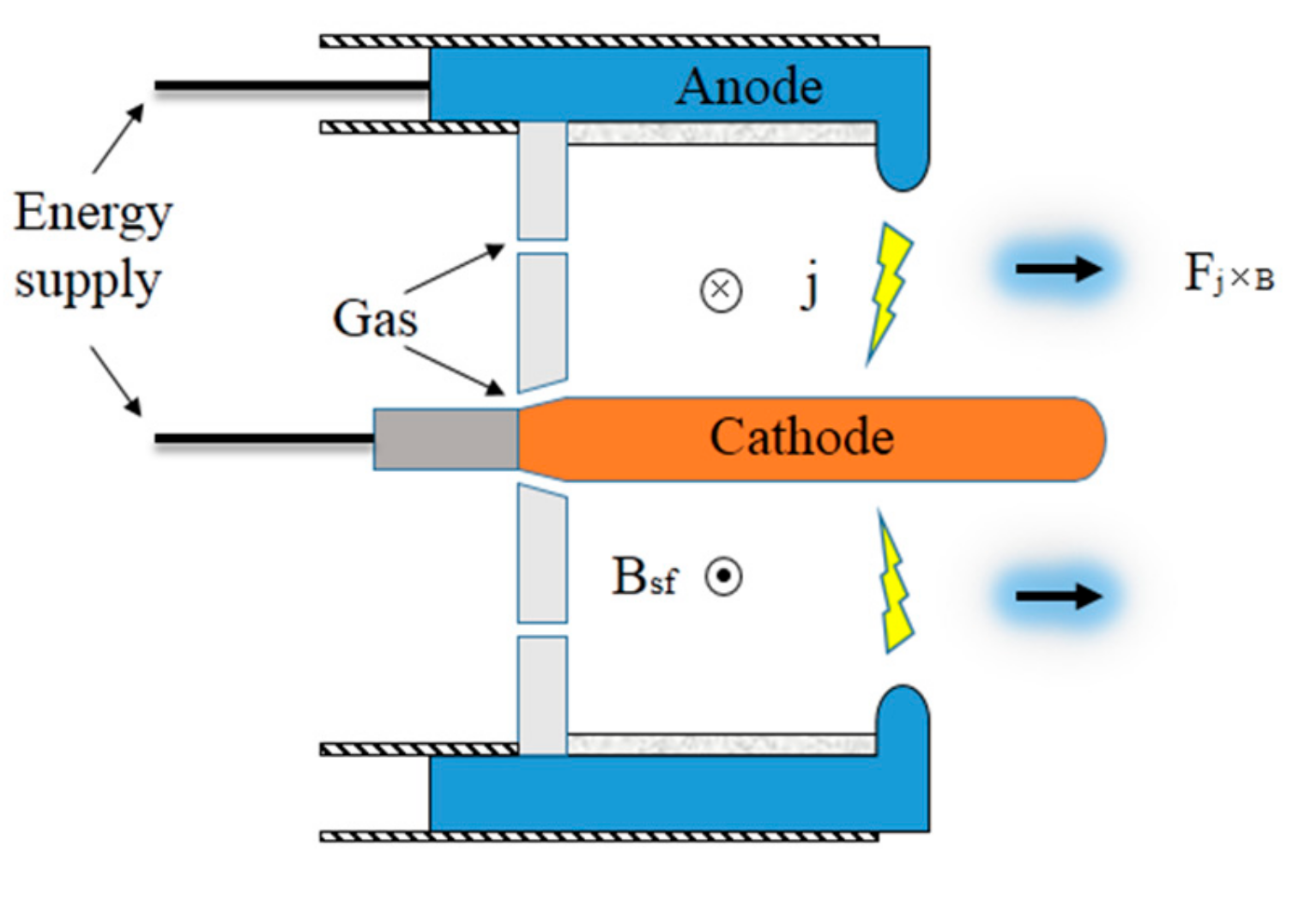
2.3. Physical Processes of a Self-Field MPDT
2.3.1. Cathode Thermionic Emission
2.3.2. Cathode Sheath
2.3.3. Anode Sheath
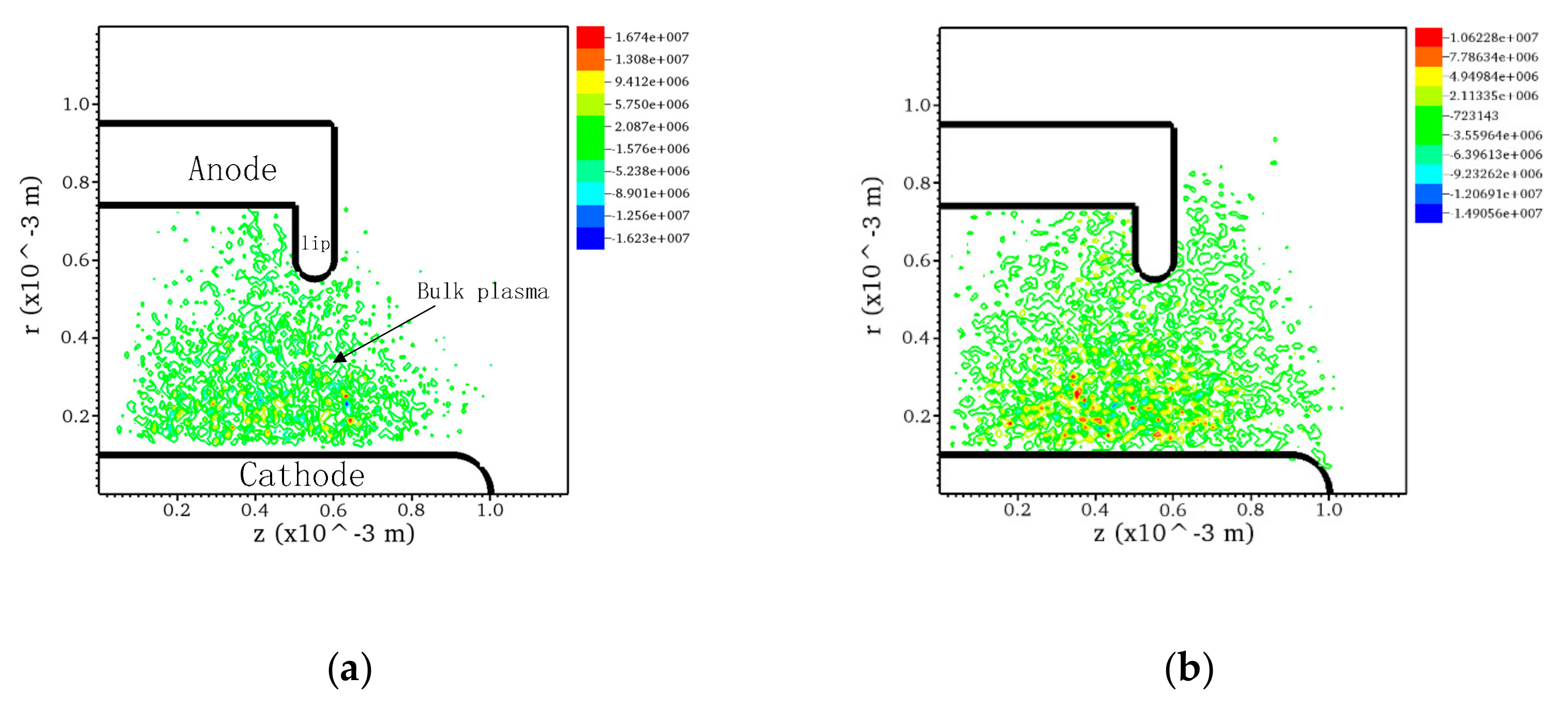
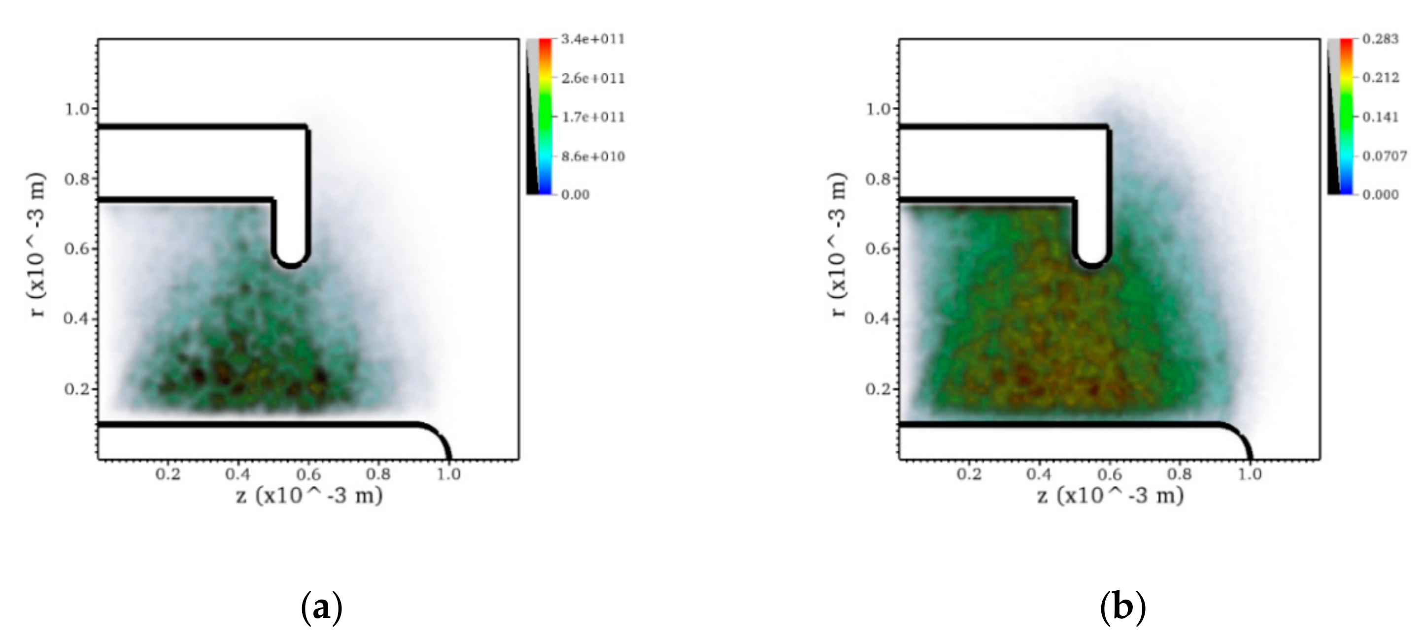
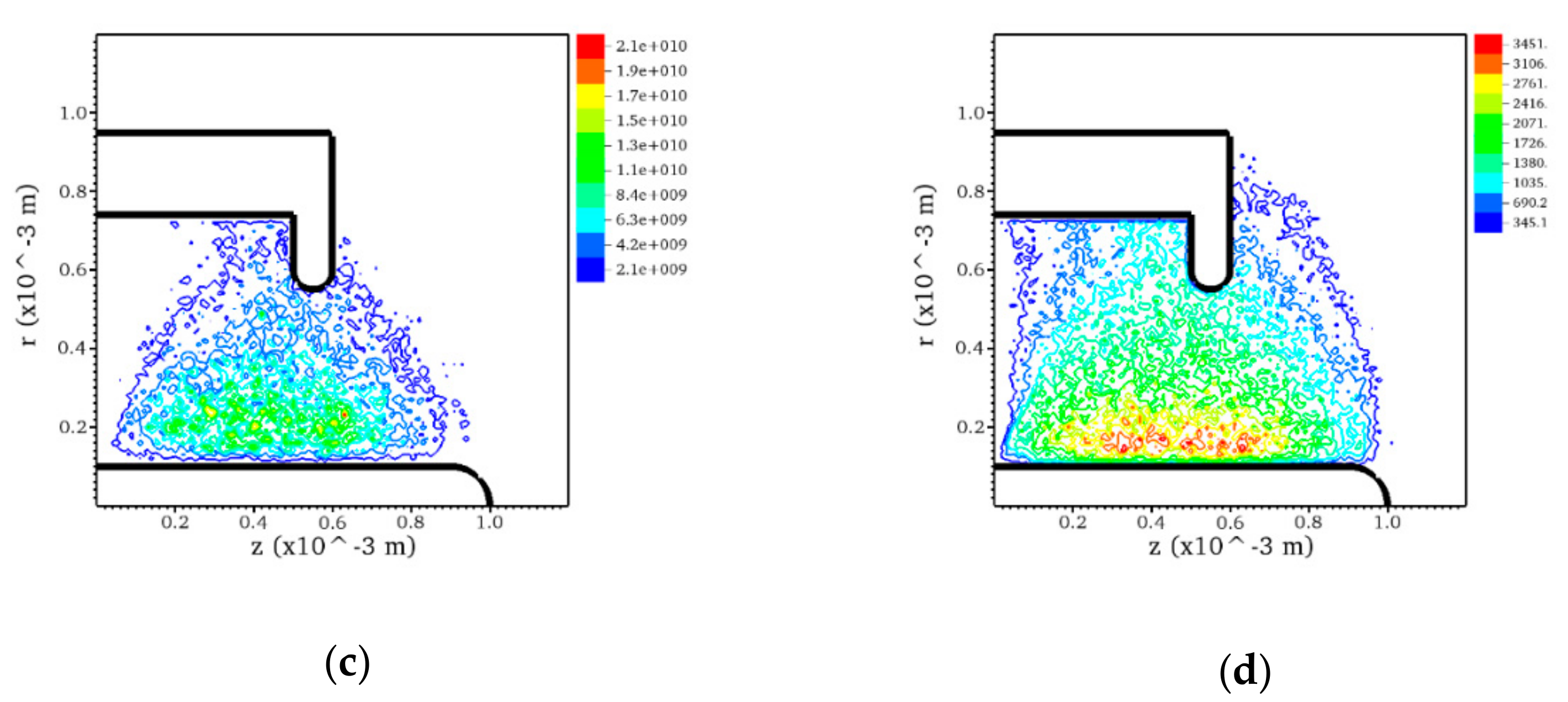
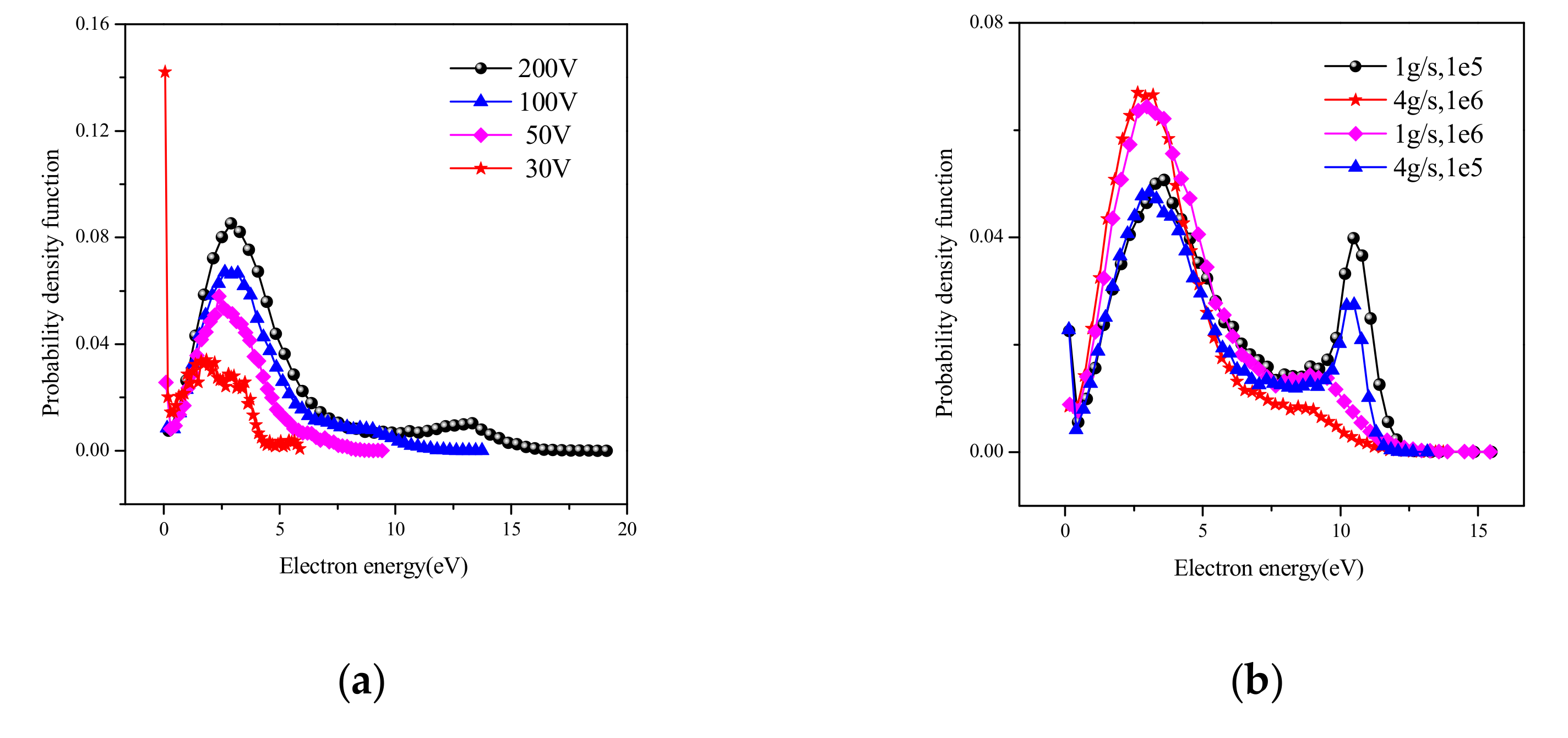
2.3.4. Bulk Plasma
2.4. Computational Method
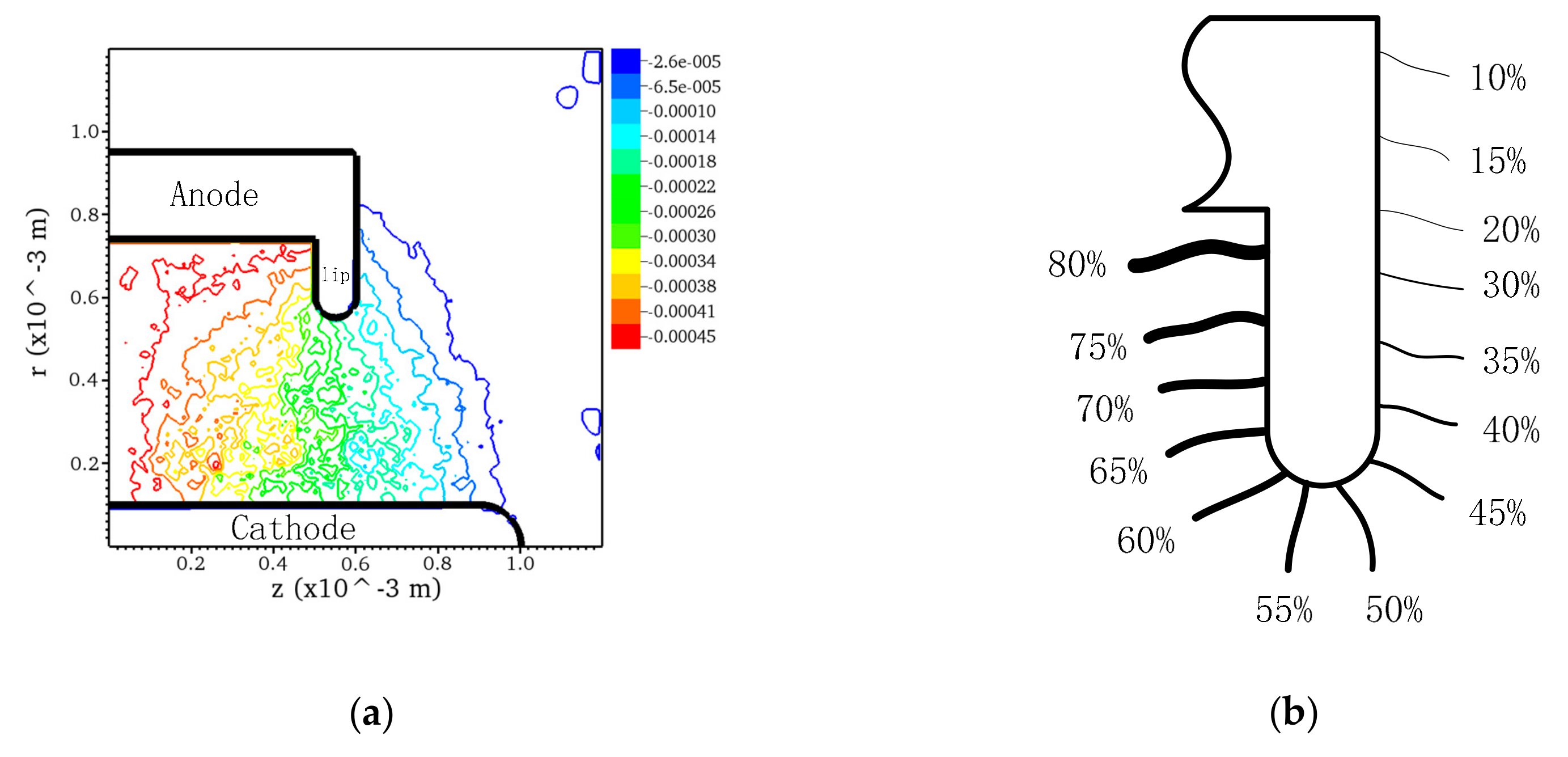
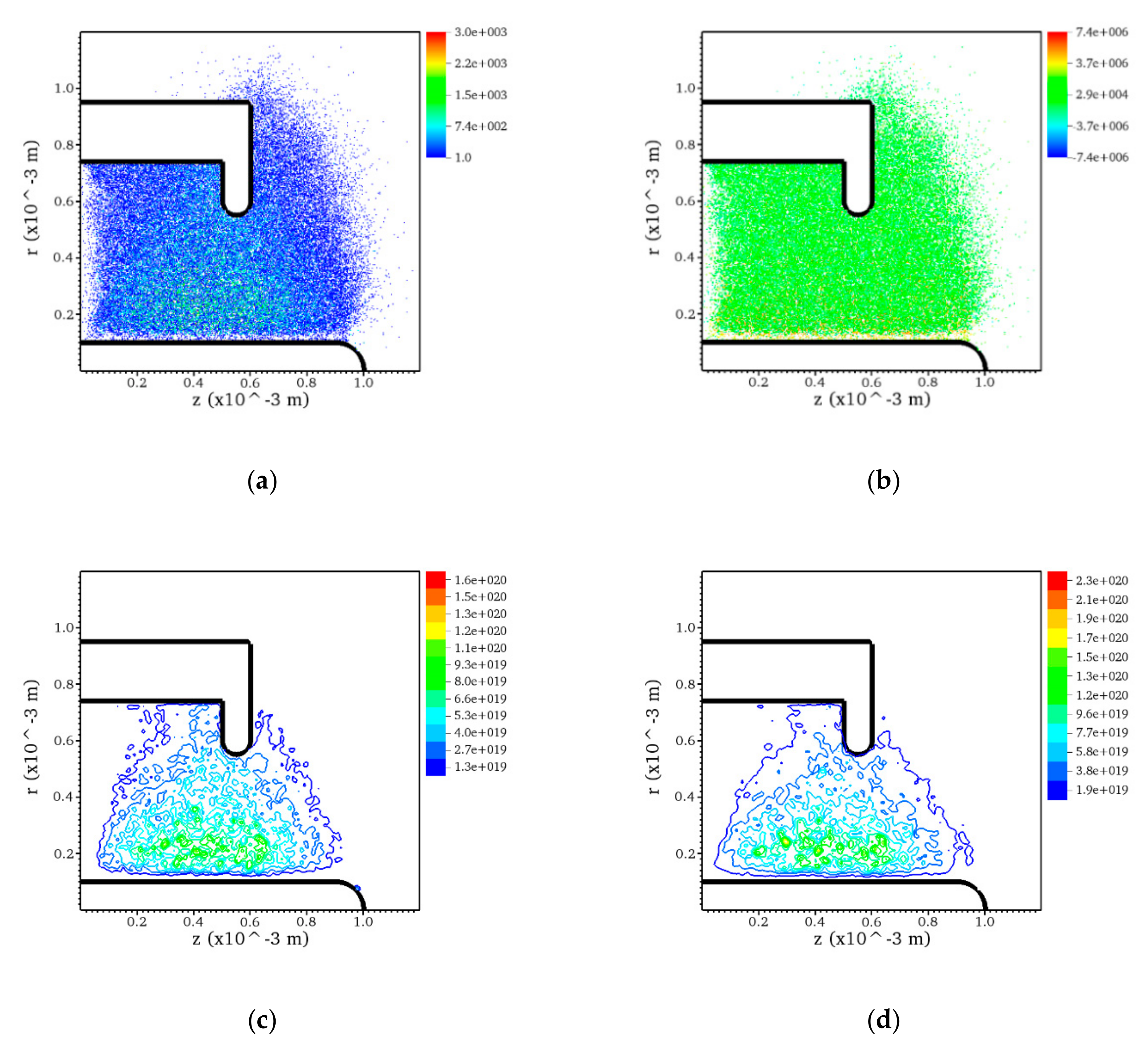
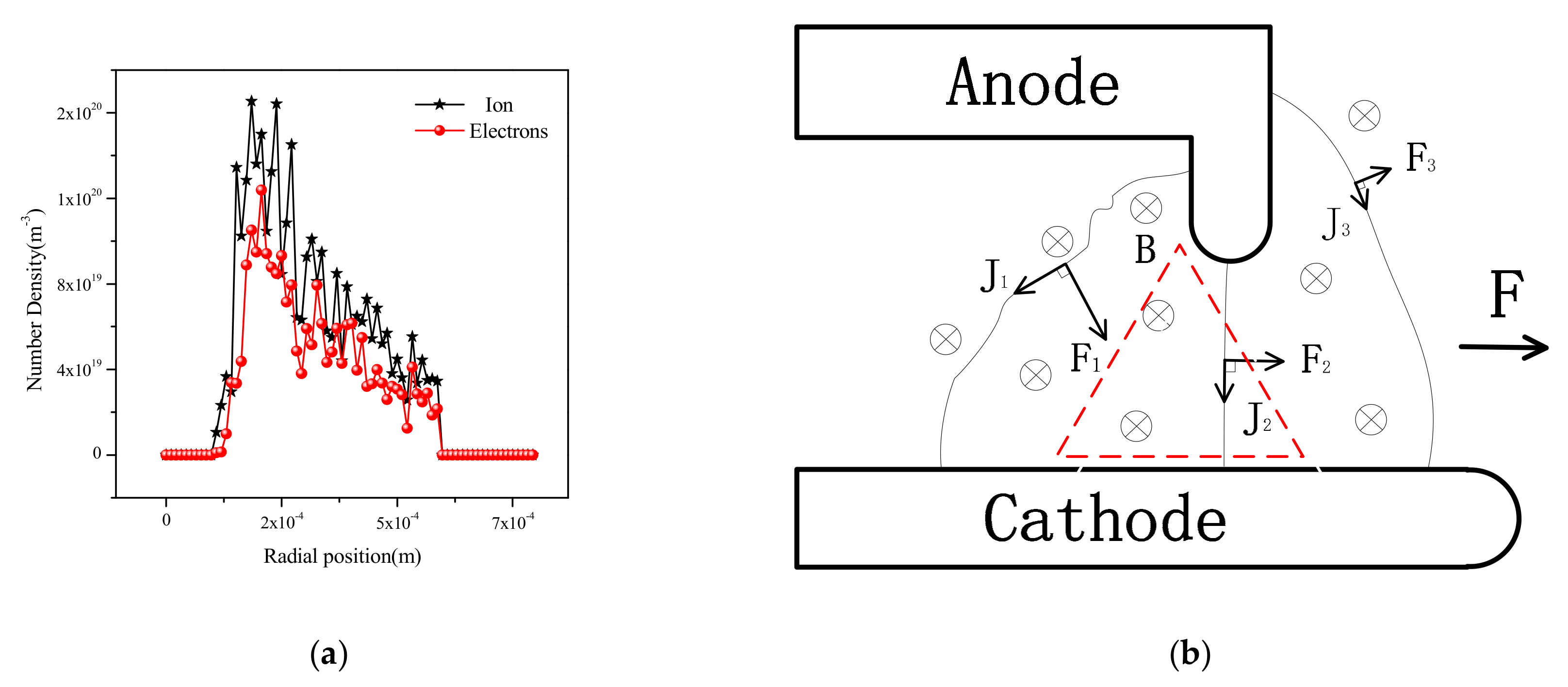
3. Results and Discussion
4. Conclusions
Author Contributions
Funding
Conflicts of Interest
Nomenclature
| B | magnetic field, Tesla |
| Bsf | induced magnetic field, Tesla |
| Bf | known function for gas, for argon Bf = 10eV |
| c | speed of light, m/s |
| E | electric field, V/m |
| Esc | energies of the scattered particles, eV |
| Einc | energies of the incident particles, eV |
| Ese | energies of the secondary electrons, eV |
| Eex | excitation threshold of gas, eV |
| Eiz | ionization threshold of gas, eV |
| j | discharge current, A |
| J | current density, A/m2 |
| Jth | thermionic current density, A/m2 |
| n | density of particles, /m2 |
| ni | number of ions |
| ne | number of electrons |
| N | number of all particles |
| Ncoll | random colliding particles |
| P | collision probability |
| Pmax | maximum collision probability |
| R | random number between 0 and 1 |
| T | temperature of cathode surface, K |
| v | velocity of particles, m/s |
| Vsc | velocity of scattered particles, m/s |
| Vinc | velocity of incident particles, m/s |
| ρq | charge quantity, C |
| νcoll | collision frequency |
| νmax | maximum collision frequency |
| σ | collision cross section, m2 |
| χ | scattering angle |
| ωpe | plasma frequency |
| λDe | Debye length, m |
References
- Gallimor, D.; Kelly, A.J.; Jahn, R.G. Anode Power Deposition in Quasisteady magnetoplasmadynamic thrusters. J. Propuls. Power. 1992, 8, 1224–1231. [Google Scholar] [CrossRef]
- Gallimore, A.D.; Kelly, A.J.; Jahn, R.G. Anode power deposition in MPD thrusters. J. Propuls. Power. 1993, 9, 361–368. [Google Scholar]
- Myers, R.M.; Kelly, A.J.; Jahn, R.G. Energy deposition in low-power coaxial plasma thrusters. J. Propuls. Power. 1990, 7, 732–739. [Google Scholar]
- Itsuro, K.; Kyoichiro, T.; Masafumi, T. Current Distribution on the Electrodes of MPD Arcjets. AIAA J. 1982, 20, 889–892. [Google Scholar]
- Michael, R.L. Numerical Simulation of Self-Field MPD Thrusters. NASA Contractor Rep. 1991, AIAA-91-2341. [Google Scholar]
- Edgar, C. Scaling of Thrust in Self-Field Magnetoplasmadynamic Thrusters. J. Propul. Power 1998, 14, 744–753. [Google Scholar]
- Sankaran, K.; Choueiri, E.Y.; Jardin, S.C. Comparison of Simulated Magnetoplasmadynamic Thruster Flowfields to Experimental Measurements. J. Propul. Power. 2005, 21, 129–138. [Google Scholar] [CrossRef]
- Jorg, H.; Monika, A.K. Numerical and Experimental Investigation of the Current Distribution in Self-Field Magnetoplasmadynamic Thrusters. J. Propul. Power. 2005, 21, 119–128. [Google Scholar]
- Kubota, K.; Funaki, I.; Okuno, Y. Numerical Investigation of Ionization and Acceleration Processed in a Self-Field MPD Thruster. In The 29th International Electric Propulsion Conference; Princeton University: Princeton, NJ, USA, 2005; 089. [Google Scholar]
- Xisto, C.M.; Páscoa, J.C.; Oliveira, P.J. A pressure-based high resolution numerical method for resistive MHD. J. Comput. Phys. 2014, 275, 323–345. [Google Scholar]
- Xisto, C.M.; Páscoa, J.C.; Oliveira, P.J. Numerical analysis of real gas MHD flow on two-dimensional self-field MPD thrusters. Acta Astronaut. 2015, 112, 89–101. [Google Scholar] [CrossRef]
- Szabo, J.J. Fully kinetic numerical modeling of a plasma thruster. Ph.D. Thesis, Massachusetts Institute of Technology, Boston, MA, USA, 2001. [Google Scholar]
- Taccogna, F.; Longo, S.; Capitelli, M. Self-similarity in Hall plasma discharges: Applications to particle models. Phys. Plasmas 2005, 12, 1–9. [Google Scholar] [CrossRef]
- Tang, H.B.; Cheng, J.; Liu, C.; York, T.M. Study of Applied Magnetic Field Magnetoplasmadynamic Thrusters with Particle-in-cell and Monte Carlo Collision. II. Investigation of Acceleration Mechanisms. Phys. Plasmas 2012, 19, 1–11. [Google Scholar] [CrossRef]
- Li, M.; Tang, H.-B.; Ren, J.-X.; York, T.M. Modeling of Plasma Processes in the Slowly Diverging magnetic Fields at the Exit of an Applied-field Magnetoplasmadynamic Thruster. Phys. Plasmas. 2013, 20. [Google Scholar] [CrossRef]
- Cheng, J.; Tang, H.B.; York, T.M. Energy conversion and transfer for plasmas in a magnetic expansion configuration. Phys. Plasmas. 2014, 21, 1–13. [Google Scholar] [CrossRef]
- Birdsall, C.K.; Langdon, A.B. Plasma Physics via Computer Simulation; Adam Hilger: Bristol, UK, 1991. [Google Scholar]
- Vahedi, V.; Surendra, M. A Monte Carlo collision model for the particle-in-cell method: Applications to argon and oxygen discharges. Comput. Phys. Commun. 1995, 87, 179–198. [Google Scholar] [CrossRef]
- Tskhakaya, D.; Matyash, K.; Schneider, R.; Taccogna, F. The Particle-In-Cell Method. Contrib. Plasma Phys. 2007, 47, 563–594. [Google Scholar] [CrossRef]
- Hong-Yu, W.; Wei, J.; Peng, S.; Ling-Bao, K. On the energy conservation electrostatic particle-in-cell Monte Carlo simulation Benchmark and application to the radio frequency discharges. Chin. Phys. B. 2014, 23, 1–9. [Google Scholar]
- Birdsall, C.K. Particle-in-cell Charged-Particle Simulations, plus Monte Carlo Collisions with Neutral Atoms, PIC-MCC. IEEE Trans. Plamsa Sci. 1991, 19, 65–85. [Google Scholar] [CrossRef]
- Verboncoeur, J.P. Particle simulation of plasmas: Review and advances. Plasma Phys. Control. Fusion 2005, 47, A231–A260. [Google Scholar] [CrossRef]
- Kaminsky, M. Atomic and Ionic Impact Phenomena on Metal Surfaces; American Elsevier: New York, NY, USA, 1968. [Google Scholar]
- Myers, R.M.; Suzuki, N.; Kelly, A.J.; Jahn, R.G. Cathode phenomena in a low-power magnetoplasmadynamic thruster. J. Propuls. Power. 1991, 7, 760–766. [Google Scholar] [CrossRef]
- Reece Roth, J. Industrial Plasma Engineering, Volume 1: Principles; IOP Publishing: London, UK, 1994. [Google Scholar]
- Puech, V.; Torchin, L. Collision cross sections and electron swarm parameters in argon. J. Phys. D Appl. Phys. 1986, 19, 2309–2323. [Google Scholar] [CrossRef]
- Yanguas-Gil, A.; Cotrino, J.; Alves, L.L. An update of argon inelastic cross sections for plasma discharges. J. Phys. D Appl. Phys. 2005, 38, 1588–1598. [Google Scholar] [CrossRef]
- Phelps, V. The application of scattering cross sections to ion flux models in discharge sheaths. J. Appl. Phys. 1994, 76, 747–753. [Google Scholar] [CrossRef]


| Particle | Collision Type | ||
|---|---|---|---|
| Electron - Neutral | Elastic | ||
| Excitation | |||
| Ionization | |||
| Ion - Neutral | Momentum exchange | ||
| Charge exchange | |||
| Number | Collision Type | Expressions of Interaction |
|---|---|---|
| 1 | Elastic | |
| 2 | Excitation | |
| 3 | Ionization | |
| 4 | Momentum exchange | |
| 5 | Charge exchange |
| Type | Physical Quantities | Original | Scaled |
|---|---|---|---|
| PIC | Length/electrodes radius | L,R | |
| Electric field | E | E | |
| Magnetic field | B | ||
| Velocity | v | ||
| Gyro-radius | r | ||
| MCC | Collision probability | P | P |
| Particle density | n | ||
| Cross-section | |||
| Energy threshold | |||
| Derivations | Mass flow rate | ||
| Current | I | ||
| Electric potential | V | ||
| Thrust | F | ||
| Specific impulse | |||
| Efficiency |
© 2019 by the authors. Licensee MDPI, Basel, Switzerland. This article is an open access article distributed under the terms and conditions of the Creative Commons Attribution (CC BY) license (http://creativecommons.org/licenses/by/4.0/).
Share and Cite
Li, J.; Zhang, Y.; Wu, J.; Cheng, Y.; Du, X. Particle Simulation Model for Self-Field Magnetoplasmadynamic Thruster. Energies 2019, 12, 1579. https://doi.org/10.3390/en12081579
Li J, Zhang Y, Wu J, Cheng Y, Du X. Particle Simulation Model for Self-Field Magnetoplasmadynamic Thruster. Energies. 2019; 12(8):1579. https://doi.org/10.3390/en12081579
Chicago/Turabian StyleLi, Jian, Yu Zhang, Jianjun Wu, Yuqiang Cheng, and Xinru Du. 2019. "Particle Simulation Model for Self-Field Magnetoplasmadynamic Thruster" Energies 12, no. 8: 1579. https://doi.org/10.3390/en12081579
APA StyleLi, J., Zhang, Y., Wu, J., Cheng, Y., & Du, X. (2019). Particle Simulation Model for Self-Field Magnetoplasmadynamic Thruster. Energies, 12(8), 1579. https://doi.org/10.3390/en12081579