Article

Speed Control of Permanent Magnet DC Motor with Friction and Measurement Noise Using Novel Nonlinear Extended State Observer-Based Anti-Disturbance Control

by
Amjad J. Humaidi
1 and
Ibraheem Kasim Ibraheem
2,*
1
Department of Control and Systems Engineering, University of Technology, Baghdad 10001, Iraq
2
College of Engineering, Department of Electrical Engineering, University of Baghdad, Al-Jadriyah, P.O.B.: 47273, Baghdad 10001, Iraq
*
Author to whom correspondence should be addressed.
Energies 2019, 12(9), 1651; https://doi.org/10.3390/en12091651
Submission received: 24 March 2019 / Revised: 16 April 2019 / Accepted: 19 April 2019 / Published: 30 April 2019
(This article belongs to the Section I: Energy Fundamentals and Conversion)

Abstract

:
In this paper, a novel finite-time nonlinear extended state observer (NLESO) is proposed and employed in active disturbance rejection control (ADRC) to stabilize a nonlinear system against system’s uncertainties and discontinuous disturbances using output feedback based control. The first task was to aggregate the uncertainties, disturbances, and any other undesired nonlinearities in the system into a single term called the “generalized disturbance”. Consequently, the NLESO estimates the generalized disturbance and cancel it from the input channel in an online fashion. A peaking phenomenon that existed in linear ESO (LESO) has been reduced significantly by adopting a saturation-like nonlinear function in the proposed nonlinear ESO (NLESO). Stability analysis of the NLEO is studied using finite-time Lyapunov theory, and the comparisons are presented over simulations on permanent magnet DC (PMDC) motor to confirm the effectiveness of the proposed observer concerning LESO.

1. Introduction

In most control industries, it is hard to establish accurate mathematical models to describe the systems precisely. Also, some terms are not explicitly known in mathematical equations and, on the other hand, some unknown external disturbances exist around the system environment. The uncertainty, which includes internal uncertainty and external disturbance, is ubiquitous in practical control systems [1].

1.1. Background

To tackle the shortcomings of passive anti-disturbance control (PADC) strategies in treating the disturbances, Han in Reference [2] has proposed the alleged active disturbance rejection control (ADRC) paradigm. Generally speaking, the basic idea behind the ADRC is to straightforwardly oppose disturbances by feedforward compensation control configuration given disturbance estimations/cancellation principle [3]. This procedure has discovered a number of practical applications [4,5]. Extended state observer (ESO) is the central part of the ADRC, which works by augmenting the mathematical model of the nonlinear dynamical system with an additional virtual state. It describes all the unwanted dynamics, uncertainties, and exogenous disturbances and is called the “generalized disturbance” or “total disturbance”. Then, this total disturbance is estimated by the ESO and fed back into the control input channel for cancelation [2,6]. It can be applied for varieties of systems like those studied in References [7,8,9,10].

1.2. Related Work

During recent years, the literature has found many types of research for analysis, design, and implementation of the ESO. Different forms of modern control theory-based observers have been proposed to meet this need where several surveys of various disturbance observers can be found in [11,12,13]. In 1971, Johnson introduced the unknown\input observer (UIO) [14] to estimate the unknown input of the system. The transfer function-based disturbance observer (DOB) [15], proposed later on by Japanese researchers, can predict the disturbance as well. The Perturbation observer (POB) was offered by Kwon and Chung in 2002 [16] in the discrete form to estimate the perturbation acted on the system. The “unknown input”, the “disturbance”, and the “perturbation” are just different names for the external disturbance, and the above observers can only deal with it. The aforementioned DOBC techniques employ some plant information for disturbance observation and control design. The ESO is the one that uses less information as only the system relative degree should be known (defined later in this paper). For that reason, the ESO has become very popular in recent years. ADRC can be understood as a combination of an extended state observer (ESO) and a state feedback controller, where the ESO is utilized to observe the generalized disturbance taken as an augmented/extended state. The state feedback controller is used to regulate the tracking error between the real output and a reference signal for the physical plant [17]. It should be remembered that the ESO together with the nonlinear plant takes the form of chain-like integrators where any of the linear or nonlinear control design methods, like those presented in [18,19,20,21,22,23], can be applied for feedback stabilization and performance enhancement.

1.3. Paper Scope and Contribution

In this paper, a new class of nonlinear extended state observers (NLESO) are proposed to actively reject the generalized disturbance for a general uncertain nonlinear system according to the principle of estimation/cancelation. For this NLESO, a saturation-like nonlinear error function was suggested to attenuate the large observer error at the starting stage and/or at the time of a discontinuous disturbance is injected to the system, consequently alleviating the peaking phenomenon. From the stability analysis of the error dynamics of NLESO observer, the finite-time stability analysis based on Lyapunov principle and self-stable region (SSR) were introduced an applied on NLESO.

1.4. Problem Statement and Motivation

Assume an n-dimensional SISO nonlinear system, which is expressed by [24],
y n ( t ) = f ( t , x 1 ( t ) , x 2 ( t ) , , x n ( t ) ) + w ( t ) + b u ( t )
which can be rewritten as a chain of integrals with nonlinear uncertainties appearing in the n-th equation,
{ x ˙ 1 ( t ) = x 2 ( t ) ,   x ˙ 2 ( t ) = x 3 ( t ) ,     x ˙ n ( t ) = f ( t , x 1 ( t ) , x 2 ( t ) , , x n ( t ) ) + w ( t ) + b u ( t ) , y ( t ) = x 1 ( t )  
where u ( t ) C ( , ) is the control input, y ( t ) the measured output, f ( · ) C ( n , ) an unknown system function, w ( t ) C ( , ) the uncertain exogenous disturbance, x ( t ) = ( x 1 ( t ) , x 2 ( t ) , , x n ( t ) ) T the state vector of the nonlinear system, and x ( 0 ) = ( x 10 , x 20 , , x n 0 ) T the initial state, L ( t ) = f ( t , x 1 ( t ) , x 2 ( t ) , , x n ( t ) ) + w ( t ) is called “generalized disturbance” [25]. By adding the extended state x n + 1 ( t ) L ( t ) = f ( t ,   . ) + w ( t ) , the system (2) can be written as,
{ x ˙ 1 ( t ) = x 2 ( t ) ,   x ˙ 2 ( t ) = x 3 ( t ) ,     x ˙ n ( t ) = x n + 1 ( t ) + b u ( t ) ,   x ˙ n + 1 ( t ) = Δ ( t ) = f ˙ ( t , x 1 ( t ) , x 2 ( t ) , , x n ( t ) ) + w ˙ ( t ) , y ( t ) = x 1 ( t )
with   x ( 0 ) = ( x 10 , x 20 , , x n 0 ,   x ( n + 1 ) 0 ) T . The following linear ESO (LESO) needs to be designed to estimate the states of the nonlinear system as well as the generalized disturbance L ( t ) and is described as [26],
{ x ^ ˙ 1 ( t ) = x ^ 2 ( t ) + β 1 ( y ( t ) x ^ 1 ( t ) ) ,   x ^ ˙ 2 ( t ) = x ^ 3 ( t ) + β 2 ( y ( t ) x ^ 1 ( t ) ) ,       x ^ ˙ ρ ( t ) = x ^ ρ + 1 ( t ) + b u ( t ) + β ρ ( y ( t ) x ^ 1 ( t ) ) ,   x ^ ˙ ρ + 1 ( t ) = β ρ + 1 ( y ( t ) x ^ 1 ( t ) ) ,  
where x ^ n + 1 ( t ) = L ^ = f ^ ( t , x 1 ( t ) , x 2 ( t ) , , x ρ ( t ) ) + w ^ ( t ) , β i , i { 1 , 2 , , ρ , ρ + 1 } is a constant observer gain to be tuned. With β i = a i ε i , where a i , i { 1 , 2 , , ρ , ρ + 1 } are pertinent constants, and ε is the constant gain or the reciprocal of observer’s bandwidth, ρ is the relative degree of the nonlinear system [24]. The observer gain is directly proportional to the observer bandwidth. Selecting a bandwidth that is too large will lead to a drop in the estimation error within an acceptable bound [27]. Therefore, the observer bandwidth is chosen to be sufficiently larger than the disturbance frequency and smaller than the frequency of unmodelled dynamics [28]. On the other hand, the performance of the ESO will be deteriorated if the bandwidth of the ESO is selected as either too low or too high. The side effects of adopting a large value for bandwidth can be summarised as the measurement noise causes a degradation on the output tracking and the control signal. Some unmodelled high frequencies dynamics may be activated beyond a certain frequency, causing inconsistency in the closed-loop system.
Motivated by the above reasons, the aim is to design a nonlinear ESO(NLESO) whose functions are as follows:
  • Its states approach as accurate as possible the states of (3) through time and coincide with them as t .
  • It reduces the peaking phenomenon.
  • It avoids large transient behaviours.
  • It guarantees fast-convergence and robustness concerning noise.
A general nonlinear extended state observer is given by,
{ x ^ ˙ 1 ( t ) = x ^ 2 ( t ) + g 1 ( y ( t ) x ^ 1 ( t ) ) , x ^ ˙ 2 ( t ) = x ^ 3 ( t ) + g 2 ( y ( t ) x ^ 1 ( t ) ) ,   x ^ ˙ ρ ( t ) = x ^ ρ + 1 ( t ) + b u ( t ) + g ρ ( y ( t ) x ^ 1 ( t ) ) ,   x ^ ˙ ρ + 1 ( t ) = g ρ + 1 ( y ( t ) x ^ 1 ( t ) )
If the nonlinear functions g i : ,   i { 1 , 2 , , ρ + 1 } were selected appropriately, the state variables of the nonlinear system could track the state variables of the original system and generalized disturbance. A nonlinear function is the mathematical fitting of “big error, small gain or small error, big gain” [29]. This function is generally selected as a nonlinear combination power function and is given as [30,31].
f a l ( e , α , δ ) = { e δ 1 α   | e | δ   | e | α s g n ( e ) | e | > δ  
where δ is a small number which is used to express the length of the linear part [32]. The f a l ( · ) is a piecewise continuous, nonlinear saturation, a monotonous increasing function.

1.5. Paper Structure

The rest of the paper is organized as follows: In Section 2, preliminary assumptions and mathematical definitions from nonlinear control theory are summarized. The main results of the proposed NLESO with the stability studies are presented in Section 3. Section 4 describes an enhanced version of ADRC with the proposed NLESO as its central core. The simulations of the enhanced ADRC on the permanent magnet DC motor are shown in Section 5. Conclusions and future work are mentioned in Section 6.

2. Basic Definitions and Assumptions

Some of the definitions of the nonlinear control theory mentioned below are needed in the mathematical analysis of the Nonlinear ESO (NLESO) proposed in this paper.
Definition 1.
[33]: Assuming that S is a region in the state space, which contains the origin. If it satisfies the condition that any system’s trajectory, which remains in it after a particular time, will eventually converge to the origin, then S is called the self-stable region (SSR) of the system.
Lemma 1.
[34,35]:the system
e ˙ = k   s g n ( e )   | e | α
is globally finite-time stable where k > 0, α ( 0 ,   1 ) . For any initial value of e(t) at t = to, i.e., e o , it is easily obtained that the solution trajectory of (7) will reach e = 0 in finite time t f = | e o | 1 α ( 1 α ) k .
Theorem 1.
[36,37]:Consider the nonlinear system x ˙ = f ( x ) with f(0) = 0. Suppose there exists a continuous function V : D on an open neighborhood D n of the origin such that the following conditions hold,
  • V(x) is positive definite.
  • V ˙ ( x ) + c V α 0 .
Then, the origin is finite-time stable, and the settling time tf depending on the initial conditions x(0) = xo is given as,
t f   V ( x o ) 1 α c ( 1 α )
for all xo in some open neighborhood of the origin, where c > 1, 0 < α < 1.
The assumptions given below are related to finite-time stability analysis of both the ESO and the closed-loop system.
Assumption (A1). The function f and w ( t ) is continuously differentiable for all ( t , x ( t ) ) × n .
Assumption (A2). The generalized disturbance L ( t ) is bounded and belongs to a known compact set L , i.e.,
s u p   L ( t )     , t
Assumption (A3). There is a positive constant M such that | Δ ( t ) | M for t 0 ,   where
Δ ( t ) = L ˙ ( t ) = f ˙ ( t , x 1 ( t ) , x 2 ( t ) , , x n ( t ) ) + w ˙ ( t ) M
Assumption (A4). The solution x i of (2) satisfy | x i ( t ) | B for some constant B > 0 for all i = 1, 2,…, n, and t   0 .

3. Main Results

In this section, the proposed NLESO will be presented followed by the stability analysis and its finite-time convergence based on self-stable region technique. The conversion of the mismatched disturbance into matched one will also be introduced.

3.1. The Proposed NLESO

The proposed NLESO for the general uncertain nonlinear system of (3) is designed as,
{ x ^ ˙ 1 ( t ) = x ^ 2 ( t ) + β 1 1 ( ω 0 ( y ( t ) x ^ 1 ( t ) ) ) , x ^ ˙ 2 ( t ) = x ^ 3 ( t ) + β 2 2 ( ω 0 ( y ( t ) x ^ 1 ( t ) ) ) , x ^ ˙ ρ ( t ) = x ^ ρ + 1 ( t ) + b u ( t ) + β ρ ρ ( ω 0 ( y ( t ) x ^ 1 ( t ) ) ) ,   x ^ ˙ ρ + 1 ( t ) = β ρ + 1 ρ + 1 ( ω 0 ( y ( t ) x ^ 1 ( t ) ) )  
where x ^ n + 1 ( t ) = L ^ , β i = a i ω 0 i 1 , ω 0 > 0 is the ESO bandwidth, and a i , i = 1, 2,….., ρ + 1, are selected according to,
a i = ( ρ + 1 ) ! i ! ( ρ + 1 i ) !
such that the characteristic equation
s ρ + 1 + a 1 s ρ + + a ρ s + a ρ + 1 = ( s + 1 ) ρ + 1
is Hurwitz, where ρ is the relative degree of the nonlinear system. The nonlinear function i : is designed as:
i ( ω 0 e ) = c i ( K α | ω 0 e | α 1 + K β | ω 0 e | β ) ω 0 e ,   i =   1 , 2 ,     ρ + 1
where K α , K β , α ,   c i ,   and   β are the positive design parameters, c i , i = 1,2,….. ρ   + 1 are used to help further reduce peaking phenomenon, a coherent problem with LESO, they are chosen such that c 1 > c 1 > > c ρ + 1 . It should be noted that the proposed NLESO estimates the states of the uncertain nonlinear system up to relative degree ρ of the nonlinear system. For the chain of integrals characterized by (2) or (3), the relative degree is ρ = n . So, the NLESO will estimate up to n-th states of (3) in addition to the generalized disturbance defined by x n + 1 ( t ) .
The proposed nonlinear function has a saturation-like profile which obeys the principle of “small error, large gain, and large error, small gain”, it is an odd function in terms of the error e. It has the following additional features: g (0) = 0 and g ( ω 0 e) = k( ω 0 e). ω 0 e, where k m i n k ( ω 0 e ) < and k ( ω 0 e ) = c i ( K α | ω 0 e | α 1 + K β | ω 0 e | β ) .

3.2. Stability Analysis of the Proposed NLESO

The convergence of the proposed NLESO is studied based on how well it estimates the states of the uncertain nonlinear system and the generalized disturbance, Theorem 2 below shows the convergence analysis in terms of the estimation error dynamics and finite-time stability.
Theorem 2.
Consider the nonlinear system of (2) and assumptions 1–4 are satisfied, then the proposed NLESO described by (10) is globally asymptotically stable, it is finite-time convergent to (3) with tf > to such that e i = 0 ,   i = 1 , 2 , . ,   n + 1 for all t > tf.
Proof. 
By introducing the augmented state x n + 1 = L into (2), we obtained (3). Moreover, set
{ e i ( t ) = x i ( t ) x ^ i ( t )     i { 1 ,   2 , n }   e n + 1 ( t ) = x n + 1 ( t ) x ^ n + 1 ( t )   i = n + 1      
It should be noted that in (12), x n + 1 ( t ) x ^ n + 1 ( t ) = L L ^ , where L and L ^ are the generalized disturbances and the estimated generalized disturbance, respectively. A direct computation shows that the estimation error dynamics of (12) satisfies:
{ x ˙ 1 ( t ) x ^ ˙ 1 ( t ) = x 2 ( t ) ( x ^ 2 ( t ) + β 1 1 ( ω 0 ( y ( t ) x ^ 1 ( t ) ) )   x ˙ 2 ( t ) x ^ ˙ 2 ( t ) = x 3 ( t ) ( x ^ 3 ( t ) + β 2 2 ( ω 0 ( y ( t ) x ^ 1 ( t ) ) )   x ˙ n ( t ) x ^ ˙ n ( t ) = x n + 1 ( t ) + b u ( t ) ( x ^ n + 1 ( t ) + b u ( t ) + β n n ( ω 0 ( y ( t ) x ^ 1 ( t ) ) ) )   x ˙ n + 1 ( t ) x ^ ˙ n + 1 ( t ) = Δ ( t ) β n + 1 n + 1 ( ω 0 ( y ( t ) x ^ 1 ( t ) ) )
Substituting (11) in (13), gives
{ e ˙ 1 ( t ) = e 2 ( t ) β 1 c 1 K α | ω 0 e 1 ( t ) | α 1 ω 0 e 1 ( t ) β 1 c 1 K β | ω 0 e 1 ( t ) | β ω 0 e 1 ( t )   e ˙ 2 ( t ) = e 3 ( t ) β 2 c 2 K α | ω 0 e 1 ( t ) | α 1 ω 0 e 1 ( t ) β 2 c 2 K β | ω 0 e 1 ( t ) | β ω 0 e 1 ( t ) e ˙ n ( t ) = e n + 1 ( t ) β n c n K α | ω 0 e 1 ( t ) | α 1 ω 0 e 1 ( t ) β n c n K β | ω 0 e 1 ( t ) | β ω 0 e 1 ( t ) e ˙ n + 1 ( t ) = Δ ( t ) β n + 1 c n + 1 K α | ω 0 e 1 ( t ) | α 1 ω 0 e 1 ( t ) β n + 1 c n + 1 K β | ω 0 e 1 ( t ) | β ω 0 e 1 ( t )
where Δ ( t ) is the derivative of the generalized disturbance L given by (9). According to Lemma 1 and Theorems 5–7 of [37], and if assumption A3 holds true, then the error dynamics of (14) are asymptotically stable, i.e., the error e 1 ( t ) in the first equation approaches zero, so do e 2 ( t ) ,   e 3 ( t ) , , e n + 1 ( t ) go to zero. Moreover, the error dynamics of (14) are finite-time stable, i.e., the NLESO converges to (3) within tf > to such that e i = 0 ,   i = 0 ,   1 , . ,   n + 1 For all t > tf.
To prove it is time-finite convergent, we use the self-stable region (SSR) approach in Reference [33] to accomplish this task as follows,
Firstly, for simplicity, assume n = 1, then the error dynamics of the NLESO is
{ e ˙ 1 ( t ) = e 2 ( t ) β 1 c 1 K α | ω 0 e 1 ( t ) | α 1 ω 0 e 1 ( t ) β 1 c 1 K β | ω 0 e 1 ( t ) | β ω 0 e 1 ( t ) e ˙ 2 ( t ) = Δ ( t ) β 2 c 2 K α | ω 0 e 1 ( t ) | α 1 ω 0 e 1 ( t ) β 2 c 2 K β | ω 0 e 1 ( t ) | β ω 0 e 1 ( t )
Define m 2 ( e 1 , e 2 ) = e 2 β 1 c 1 K α | ω 0 e 1 ( t ) | α 1 ω 0 e 1 ( t ) β 1 c 1 K β | ω 0 e 1 | β ω 0 e 1 + k q 1 ( e 1 )   s g n ( e 1 ) where q 1 ( e 1 ( t ) ) is positive definite continuous function, i.e., q 1 ( 0 ) = 0 , k > 1. Also, define S = { e 1 , e 2 :   | m 2 ( e 1 , e 2 ) | q 1 ( e 1 ) } , assume that there exists ( e 1 , e 2 ) S ,   t > T . According to the structure of S
e 2 β 1 c 1 K α | ω 0 e 1 ( t ) | α 1 ω 0 e 1 ( t ) β 1 c 1 K β | ω 0 e 1 | β ω 0 e 1 + k q 1 ( e 1 )   s g n ( e 1 ) q 1 ( e 1 )
or
e 2 β 1 c 1 K α | ω 0 e 1 ( t ) | α 1 ω 0 e 1 ( t ) β 1 c 1 K β | ω 0 e 1 | β ω 0 e 1 q 1 ( e 1 ) k q 1 ( e 1 )   s g n ( e 1 ) .
Choose a Lyapunov candidate function V( e 1 ( t ) ) as
V ( e 1 ( t ) ) = 0 e 1 ( t )   e 1 ( t ) d e 1 ( t )
Then,
V ˙ ( e 1 ( t ) ) = e 1 d e 1 ( t ) d t = e 1 ( e 2 ( t ) β 1 c 1 K α | ω 0 e 1 ( t ) | α 1 ω 0 e 1 ( t ) β 1 c 1 K β | ω 0 e 1 ( t ) | β . ω 0 e 1 ( t ) ) .
Substituting (16) in (17), we get
V ˙ ( e 1 ( t ) ) | e 1 | ( q 1 ( e 1 ) k q 1 ( e 1 )   ) ( k 1 ) | e 1 |   q 1 ( e 1 ) .
From the positiveness definition of q 1 ( e 1 ) and since k > 1, we conclude that V ˙ ( e 1 ( t ) ) is negative definite. Hence,
t e 1 ( t ) 0
and based on the structure of S
t e 2 ( t ) 0
Let q 1 ( e 1 ) = k 1 | e 1 ( t ) | α , with k 1 > 0 and 0 <   α <1. With this choice of q 1 ( e 1 ) , V ˙ ( e 1 ( t ) ) becomes
V ˙ ( e 1 ( t ) ) r | e 1 | 1 + α
From V ( e 1 ( t ) ) = 0 e 1 ( t )   e 1 ( t ) d e 1 ( t ) , one can deduce that V = e 1 2 2 or e 1 = ( 2 V ) 1 2 , and V ˙ ( e 1 ( t ) ) gets its final form as
V ˙ ( e 1 ( t ) ) r ( 2 V ) 1 + α 2
with r = ( k 1 )   k 1 . According to Theorem 1, the error dynamics of (15) is finite-time convergent with
t f   V ( e 1 ( t 0 ) ) 1 α ˜ c ( 1 α ˜ )
where α ˜ = 1 + α 2 . □
Remark 1.
The proof of the first part of Theorem 3 is based on the Filippov sense, where any discontinuous differential equation x ˙ = v ( x ) , x n , and v is a locally bounded measurable vector function, is replaced by an equivalent differential inclusion x ˙ V ( x ) (see Reference [38]). While the second part was proved by self-stable region approach defined in Definition 1, see Reference [39] and the references therein.
The dynamics of the proposed NLESO given by (10) can be represented in terms of (14) as,
{ x ^ ˙ 1 ( t ) = x ^ 2 ( t ) + e 2 ( t ) e ˙ 1 ( t ) , x ^ ˙ i ( t ) = x ^ i + 1 ( t ) + e i + 1 ( t ) e ˙ i ( t )   ,   i = 1 , , n 1   x ^ ˙ n ( t ) = x ^ n + 1 ( t ) + e n + 1 ( t ) e ˙ n ( t ) + u ( t ) x ^ ˙ n + 1 ( t ) = Δ ( t ) e ˙ n + 1 ( t )  
The dynamics (20) tells us that the states of the NLESO suffer from observer error dynamics (14).

3.3. Mismatched Disturbance and System of Integrals Chain

The original ESO in the works [2,3] assume that the plant is expressed in the integral chain form (ICF) satisfying the matched condition (Brunovsky form) [40]. Therefore, its applicability is restricted to systems which, directly or using a change of variable, can be expressed in the ICF. Performing such transformation is not always easy, as mentioned in [41,42], especially if the system has zero-dynamics. Furthermore, in certain nonlinear systems, the disturbances appear in the system in a different channel of the control input and hence does not satisfy the matching condition. Consequently, the standard manipulation of ADRC for this mismatched disturbance is no longer available. For example, assume the following uncertain nonlinear system,
{ x ˙ 1 ( t ) = f 1 ( x 1 ( t ) , x 2 ( t ) , , x n ( t ) ) + b 1 d 1 ( t )     x ˙ i ( t ) = f i ( x 1 ( t ) , x 2 ( t ) , , x n ( t ) ) + b i d i ( t )   x ˙ n ( t ) = f n ( x 1 ( t ) , x 2 ( t ) , , x n ( t ) ) + b n u ( t ) + b n d n ( t ) y ( t ) = x 1 ( t )  
where x ( t ) = ( x 1 ( t ) , x 2 ( t ) , , x n ( t ) ) T n, u , y ( t ) are the states of the system, the control input, and the system output, respectively. f i , are smooth function and are differentiable and f i (⋅) ≠ 0 for i = 1, 2, …, n−1, d i ( t )   represents the external mismatched disturbance, d n is the matched disturbance.
Therefore, motivated by the successful results of the ESO, it was recently pointed out in Reference [43] that it is imperative to develop ESO-based control techniques for systems without assuming the ICF and satisfying the matching condition (the disturbance must appear on the same channel of the control input, i.e., Brunovsky form). The next theorem is proposed to deal with mismatch disturbances and uncertainties assuming n = 2 for simplicity and omitting the time variable t from the dynamic equations for succinctness.
Theorem 3.
Consider the second-order affine nonlinear dynamical system with mismatched disturbance satisfying assumption A2 represented by,
{ x ˙ 1 = f 1 ( x 1 , x 2 ) + b 1 d   x ˙ 2 = f 2 ( x 1 , x 2 ) + b 2 u   y = x 1  
The above system can be transformed into the nonlinear model satisfying the matching condition (Brunovsky form) with the state-space given by,
{ x ˜ ˙ 1 = x ˜ 2   x ˜ ˙ 2 = f ^ ( x ˜ 1 , x ˜ 2 ,   x 2 ) + b ^ ( u + d ^ )   y = x ˜ 1  
where f ^ ( x 1 , x 2 ) = f 1 ( x 1 , x 2 ) x 1 f 1 ( x 1 , x 2 ) + f 1 ( x 1 , x 2 ) x 2 f 2 ( x 1 , x 2 ) , b ^ = b 2 f 1 ( x 1 , x 2 ) x 2 ,
d ^ = ( b 1 f 1 ( x 1 , x 2 ) x 1 d + b 1 d ˙ ) / ( b 2 f 1 ( x 1 , x 2 ) x 2 ) .
Remark 2.
It must be noted that the matched disturbance d ^   or d ^ n e w is different from the original mismatched disturbance d of (22) in the sense that, after being transformed into the same channel of the control input, it is expressed in terms of the dynamic states of the nonlinear system and derivative of the original mismatched disturbance. In effect, the proposed NLESO will, in real-time manner, estimate and cancel f ^ ( x ˜ 1 , x ˜ 2 ,   x 2 ) + d ^ , and depending on how well the NLESO estimate the dynamic states of the nonlinear system and the generalized disturbance, the nonlinear system together with the NLESO will look like a chain of integrals up to the relative degree ρ of the original uncertain nonlinear system.

4. Application of The Proposed NLESO in ADRC

The classical active disturbance rejection control (ADRC) proposed by Han [2] is built by combining the tracking differentiator (TD), the nonlinear state error combination (NLSEF), and the linear extended state observer (LESO). In this work, an enhanced version of the ADRC(EADRC), which is called EADRC-NLESO, is illustrated to emphasize that the proposed NLESO is employed in the design; it consists of a second-order nonlinear differentiator (SOND) [44], an improved nonlinear state error feedback (INLSEF) controller [45], and the proposed NLESO. In the improved INLSEF controller, the algorithm uses the sign(.) together with the exponential function, which are integrated as follows: u I N L S E F = u o = Ψ ( e ) = k ( e ) T f ( e ) + u i n t , where e n is the vector of the state error, defined as e = [ e ( 0 ) . e ( i ) . e ( n 1 ) ] T . In this regard, e ( i ) is the i-th derivative of the state error defined as, e ( i ) = x ( i ) z ( i ) . The function k(e) and the function f(e) are defined in Reference [45]. It must be mentioned that u i n t = 0 in our work, where integral action in ADRC is almost achieved by the ESO. Supposedly, the ESO will estimate and cancel online all the errors caused by any kind of discrepancy in the nonlinear system including the external disturbances. The NLESO (for n = 2) has the following state-space representation,
{ x ^ ˙ 1 = x ^ 2 ( t ) + β 1 c 1 [ K α | ω 0 ( y x ^ 1 ( t ) ) | α s i g n ( ω 0 ( y x ^ 1 ( t ) ) ) + K β | ω 0 ( y x ^ 1 ( t ) ) | β ( ω 0 ( y x ^ 1 ( t ) ) ) ]   x ^ ˙ 2 = x ^ 3 ( t ) + b u + β 2 c 2 [ K α | ω 0 ( y x ^ 1 ( t ) ) | α s i g n ( ω 0 ( y x ^ 1 ( t ) ) ) +   K β | ω 0 ( y x ^ 1 ( t ) ) | β ( ω 0 ( y x ^ 1 ( t ) ) ) ]   x ^ ˙ 3 = β 3 c 3 [ K α | ω 0 ( y x ^ 1 ( t ) ) | α s i g n ( ω 0 ( y x ^ 1 ( t ) ) ) +   K β | ω 0 ( y x ^ 1 ( t ) ) | β ( ω 0 ( y x ^ 1 ( t ) ) ) ]
where x ^ ( t ) = [ x ^ 1 ( t ) , x ^ 2 ( t ) , x ^ 3 ( t ) ] T 3 , is a vector that includes the predictable states of the plant and the total-disturbance. The coefficients β 1 = 3 ,   β 2 = 3 ω o ,   β 3 = ω o 2 ,   K α ,   α ,   K β , c 1 , c 2 , c 3 and β + are NLESO design parameters.
Another structure of ADRC was designed to compare the performance of the proposed EADRC-NLESO with it. It has the same configuration of the EADRC-NLESO, but with LESO instead of the NLESO; throughout the simulations, it is referred to as EADRC-LESO. Based on the above, the control signal, which actuates the nonlinear system in the ADRC paradigm, is given by,
v = u o x ^ 3 ( t ) b .
It is worthy to mention that other ADRC configurations like those presented in [46,47,48,49] can be used in the comparison, however, the one with the better performance has been used in this work.

5. Simulations Results

As an application of the EADRC, the following numerical simulations include the nonlinear control of the permanent magnet DC (PMDC) motor shown in Figure 1 with Coulomb friction force using EADRC. The nonlinear model of the PMDC motor, including the external disturbance, is of a mismatched type, see (26). Applying Newton’s law and Kirchoff’s law, we get the following equations,
{ J e q d 2 θ d t 2 = T T L b e q d θ d t   L d i d t = R i + v e   =   { d 2 θ d t 2 = 1 J e q ( K t i T L b e q d θ d t ) d i d t = 1 L ( R i + v K b d θ d t )  
where v is the input voltage applied to the motor (Volt), K b is electromotive force constant (Volt/rad/s), K t is the torque constant (N.m/A), R is the electric resistance constant(Ohm), L is the electric self-inductance (Henry), J e q is the total-equivalent moment of inertia(kg.m2), J e q = Jm+ JL/N2, where JL is the load moment of inertia (kg.m2), Jm is the motor armature moment of inertia(kg.m2), b e q is the total-equivalent viscous damping of the combined motor rotor and load (N.m/rad/s), b e q = bm+ bL/N2, bm is the motor’s rotor damping (N.m/rad/s), and bL is the load viscous damping (N.m/rad/s), N is the gearbox ratio, T L (N.m) is the load torque applied at the motor side.
Applying the transformation of Appendix A, we get a simplified model for the nonlinear state-space representation of the PMDC motor expressed in Brunovsky form given by [3],
{ x ˙ 1 =   x 2 x ˙ 2 = R   b e q + K t K b L   J e q x 1 ( L   b e q + R   J e q ) L   J e q x 2 +   K t L   J e q ( v + d ) y = x 1 / N  
The detailed derivation of (27) can be found in Appendix B. As can be seen, the relative degree ρ = n . The state x 1 is the angular velocity (rad/s) of the PMDC motor before dividing the actual angular velocity of the motor shaft d θ d t by the gear ratio N, while the output y is measured after the gearbox, i.e., y = 1 N x 1 . The state x 2 is the angular acceleration (rad/s2). The equivalent disturbance at the input is given as d = L K t T ˙ L R K t T L and T L (N.m) is the load torque applied at the motor side. The load torque is given as
T L = 1 N ( T e x t + F c s g n ( x 1 ) )
where F c is the Coulomb friction force [50]; it is a nonlinear function of x 1 , which is why the system of (27) is nonlinear, T e x t is the external disturbance torque, usually of discontinuous type. The values of the parameters for PMDC motor are [51]: Ra = 0.155, La = 0.82, Kb = 1.185, Kt = 1.188, n = 3.0, Jeq = 0.275, and beq = 0.392, F c = 1 . The parameters of the proposed EADRC-NLESO are as follows, INLSEF: k11 = 1.955, k12 = 1.222, k21=0.502, k22 = 3.265, μ1 = 4.925, μ2 = 3.744, α1 = 0.693, α2 = 0.770. The SOND: a = 0.978, b = 5.587, c = 8.386, σ = 26.5. The NLESO: ω o = 35 , Kα = 0.999, α = 0.3013, Kβ = 0.38, β = 0.305, β1 = 3, β2 =105, β3 = 1225, c1 = 0.5, c2 = 0.125, c3 = 0.0625. While the parameters of the EADRC-LESO are, INLSEF: k11 = 1.763, k12 = 0.7199, k21= 0.762, k22 = 3.04, μ1 = 8.69, μ2 = 2.35, α1 = 0.688, α2 = 0.644. The SOND: a = 0.978, b = 5.587, c = 8.386, σ = 26.5. The LESO: ω o = 35 , β1 = 105, β2 = 3675, β3 = 42875.
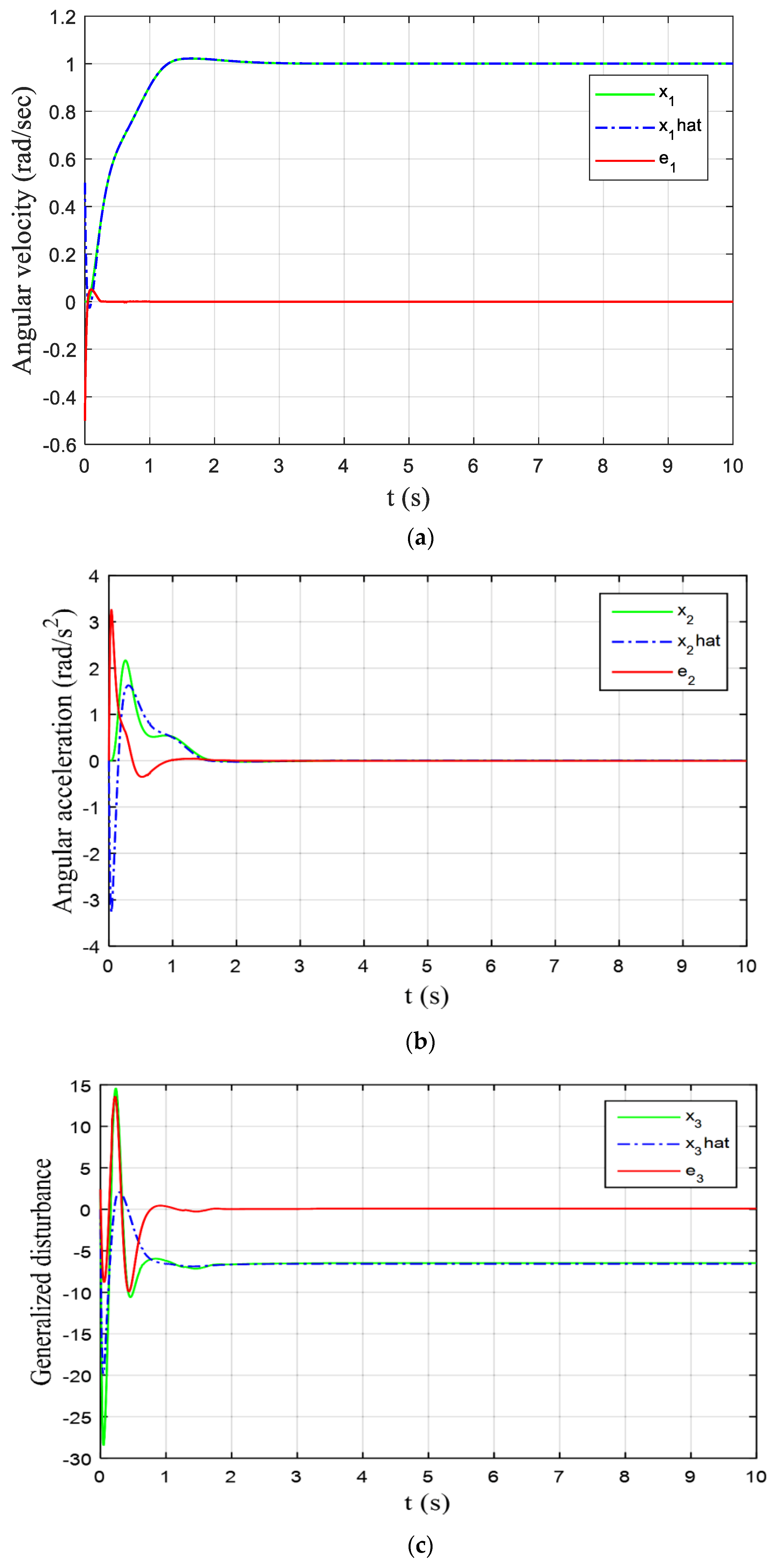
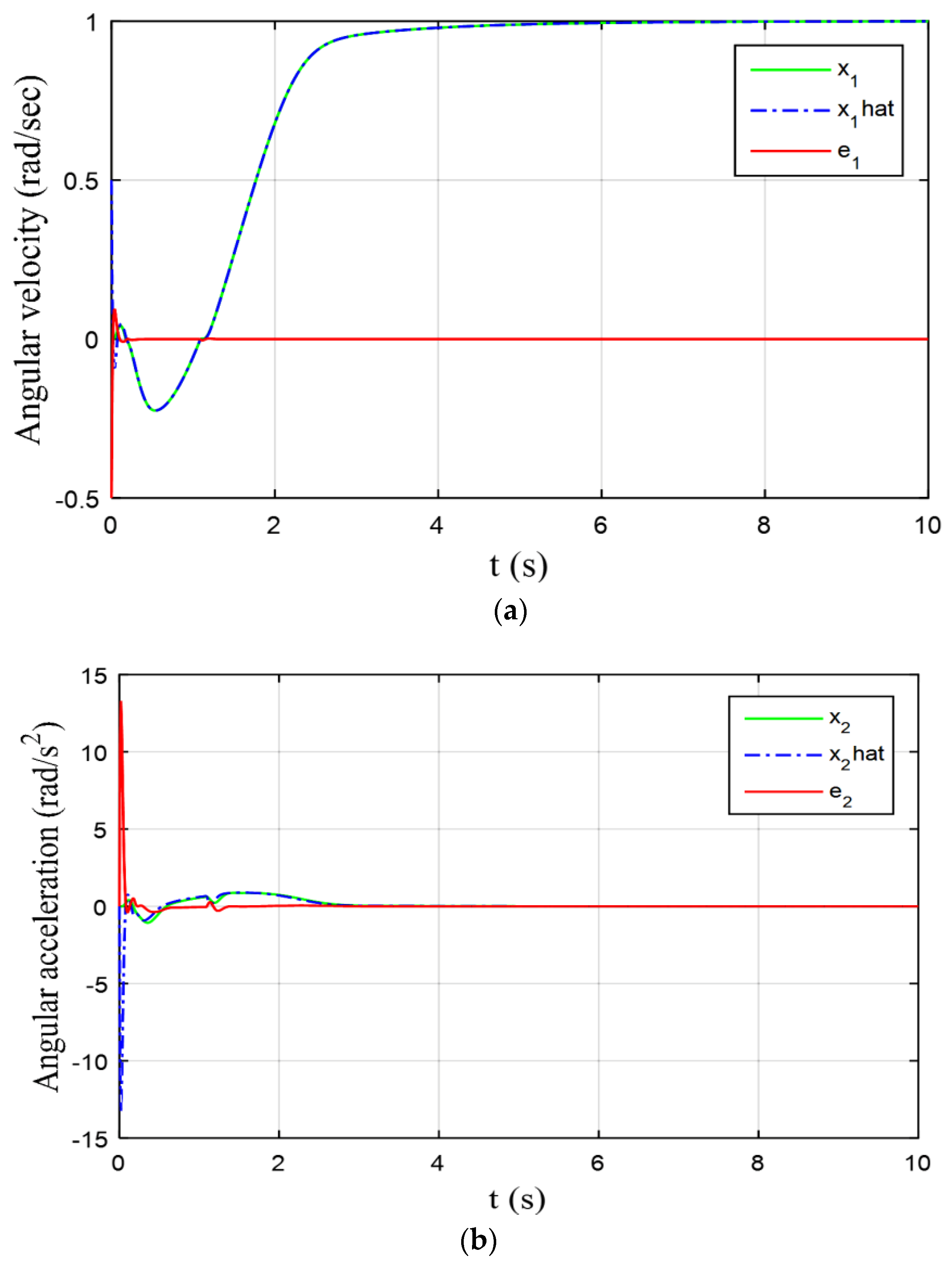
The PMDC controlled by both EADRC-NLESO and EADRC-LESO is tested by applying a reference angular-velocity equal to 1 rad per second at t = 0 and for Tf = 10 s. To verify “Peaking Phenomenon”, the initial conditions of both NLESO and LESO were set to x ^ 1 ( 0 ) = 0.5 , x ^ 2 ( 0 ) = x ^ 3 ( 0 ) = 0 , and that of the PMDC motor were, x 1 ( 0 ) = x 2 ( 0 ) = x 3 ( 0 ) = 0 . The results are shown in Figure 2 and Figure 3.
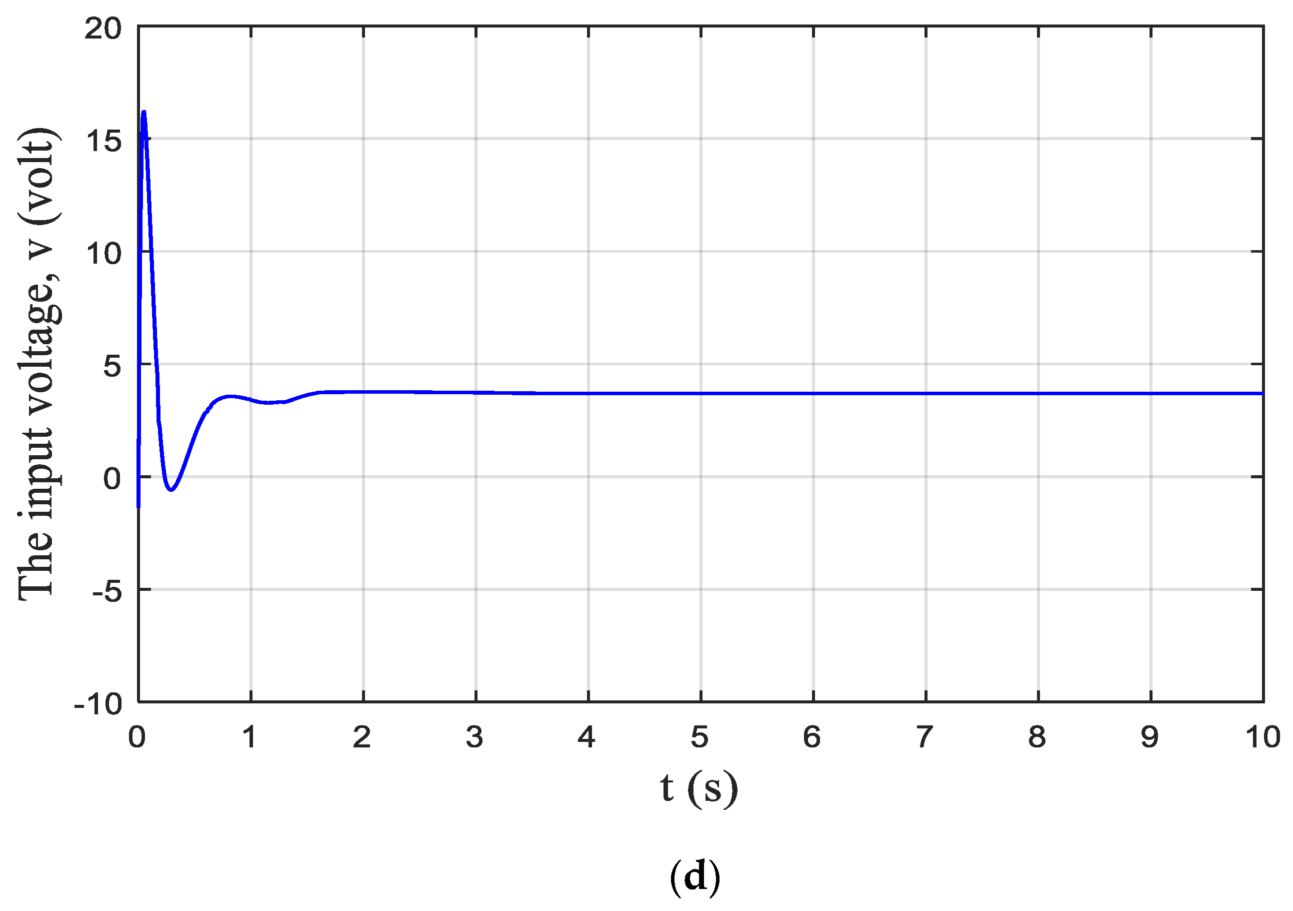
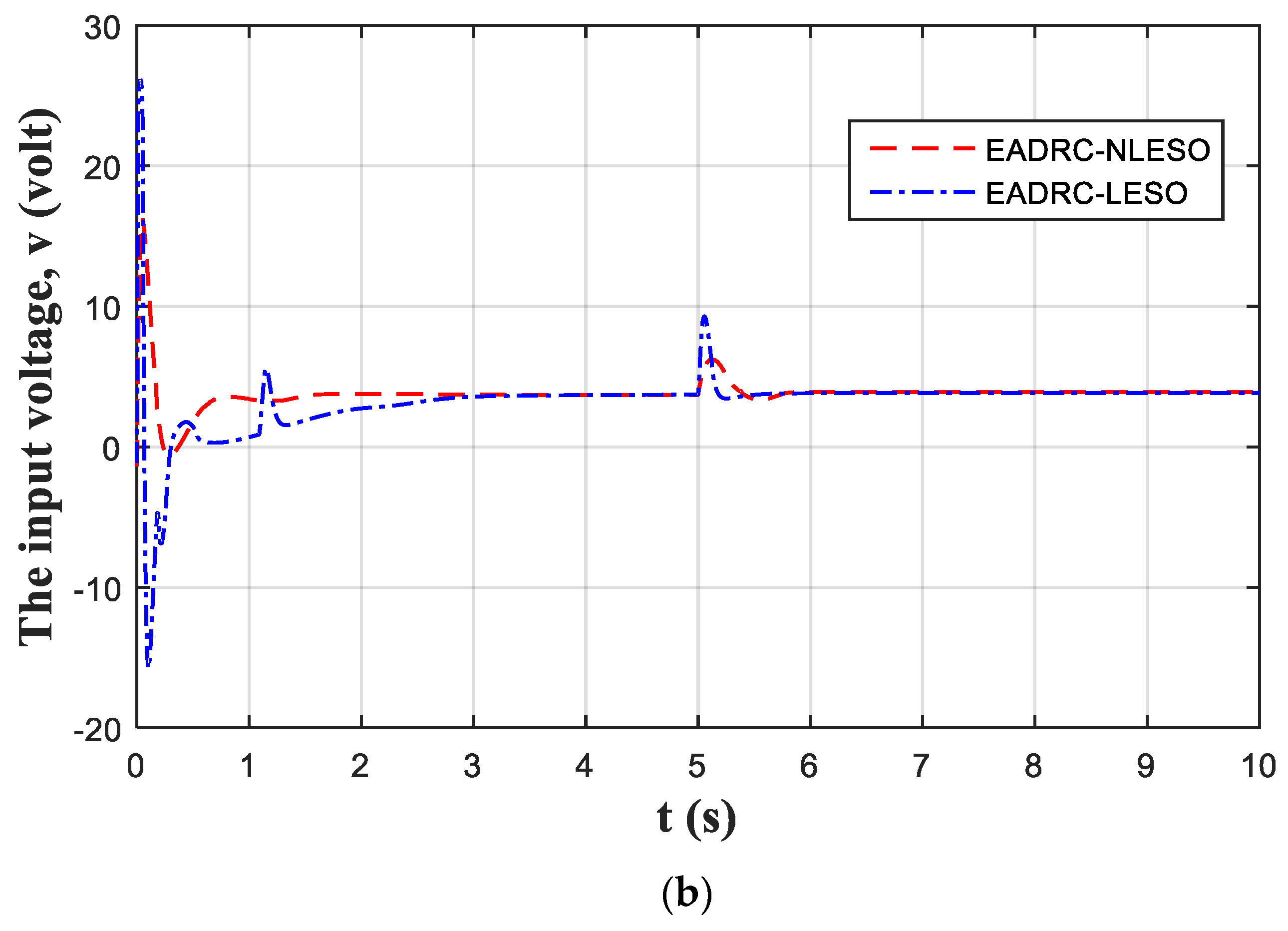
For ω o = 35 , the output responses of the PMDC motor system of (27) using EADRC-NLESO are plotted in Figure 2. The angular velocity x 1 ( t ) and its estimation x ^ 1 ( t ) are drawn in Figure 2a, while the angular acceleration x 2 ( t ) and its estimation x ^ 2 ( t ) are plotted in Figure 2b. The generalized disturbance x 3 ( t ) together with its estimation are depicted in Figure 2c. It can be seen that the estimation using NLESO is almost guaranteed. For the same ω o , the numerical results of the PMDC motor of (27) are plotted in Figure 3, but using EADRC-LESO. It was clear that the LESO satisfactorily achieved state and generalized disturbance estimation, but suffers from “Peaking phenomenon”, where x ^ 1 ( t ) peaks to −0.225, x ^ 2 ( t ) to −13.3, and x 3 ( t ) to −139.6, compared to NLESO where x ^ 1 ( t ) peaks to −0.026, x ^ 2 ( t ) to −3.27, and x 3 ( t ) did not peak. The underestimation in generalized disturbance x ^ 3 ( t ) (i.e., x 3 ( t ) does not exactly follow x 3 ( t ) ) can be treated successfully by increasing ω o , but on the account of noise filtration. The control signal in EADRC-LESO peaks down to −16 volts and up to 26 volts, whereas it peaks just to about 16.5 volts in EADRC-NLESO. It is apparent that the peaking in EADRC-NLESO is much smaller than that of EADRC -LESO.
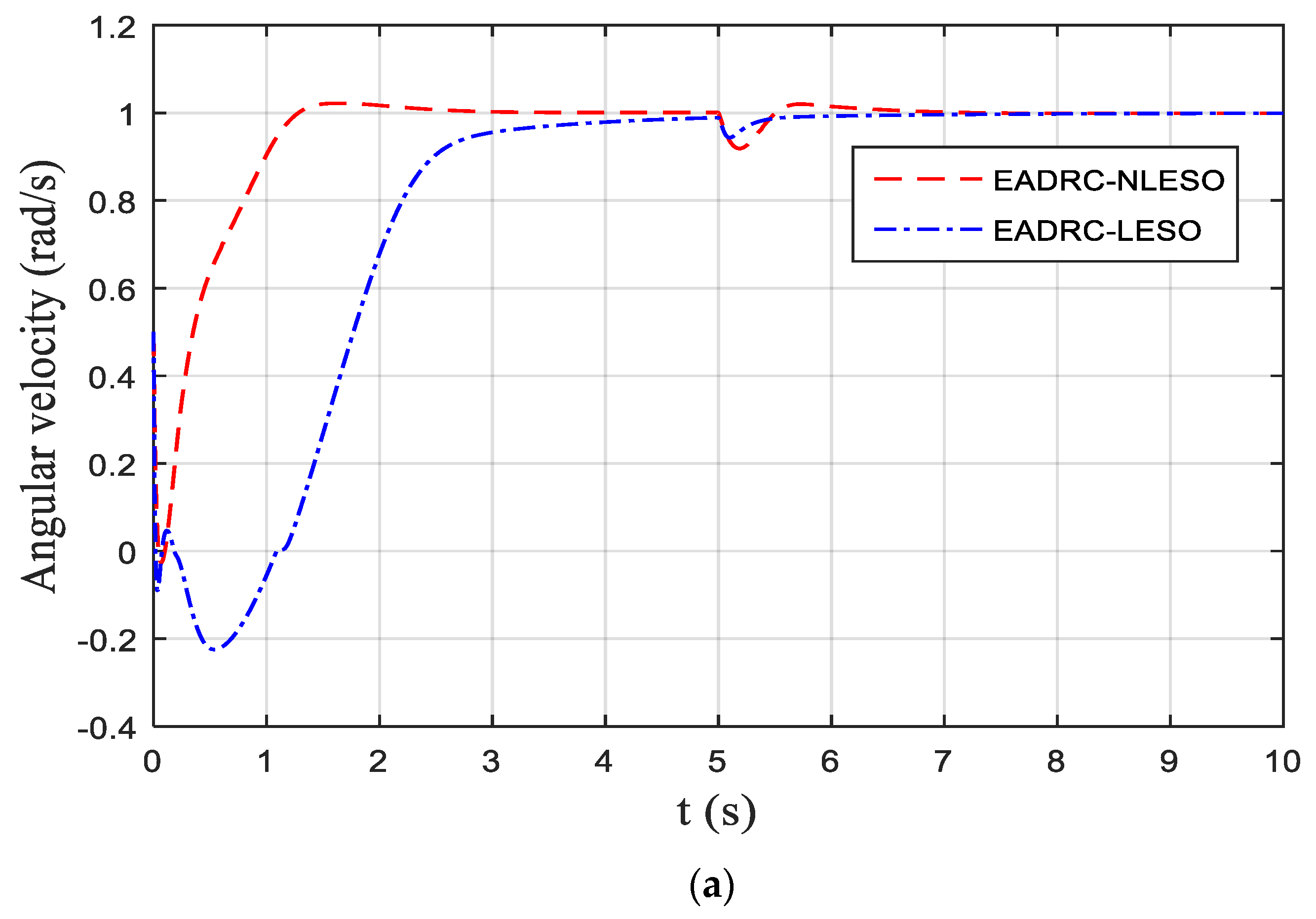
To investigate the performance of the proposed NLESO to an exogenous disturbances, an experiment was conducted with an external torque acting as a step disturbance equal to 2 N.m ((2 N.m/3) = 0.666 N.m seen from the rotor side) is applied after the gearbox during the simulation at t = 5 s using MATLAB Simulink environment. The numerical results are shown in Figure 4. From this figure, it is easy to verify that both methods cancel the effect of the disturbance on the angular velocity efficiently with the EADRC-NLESO exhibiting an undershoot larger than that of the EADRC-LESO (see Figure 3a, at t = 5). The integration-time-absolute-error (ITAE) performance measure defined as,
ITAE = 0 10 t × | r y |   d t
where y is the PMDC motor angular velocity output, and r is the reference signal, is used to measure the performance of both NLESO and LESO at steady-state. Its value in EADRC-LESO is 2.238, and the ITAE value using EADRC-NLESO is 0.485. It is clear that EADRC-NLESO outperforms EADRC-LESO significantly. Also, the control signal in the EADRC-LESO had a high peak at the starting and fluctuated after that until it reached the time of disturbance occurrence, again overshooting to 9.3 volts. On the other hand, the control signal in EADRC-NLESO overshoots with positive values only and to the half of that in EADRC-LESO. This leads to an increase of the energy required in the EADRC-LESO case, where an energy index defined as the integral square of the control signal (u) denoted as ISU is used to measure how much energy the control scheme requires, i.e.,
ISU = 0 10   u 2 d t
Based on ISU index, the control energy in EADRC-NLESO is 161.600 and 172.922 in EADRC-LESO. It must be mentioned that a limiter of 12   volts has been placed before the PMDC motor to limit the control signal input within the safe bounds.
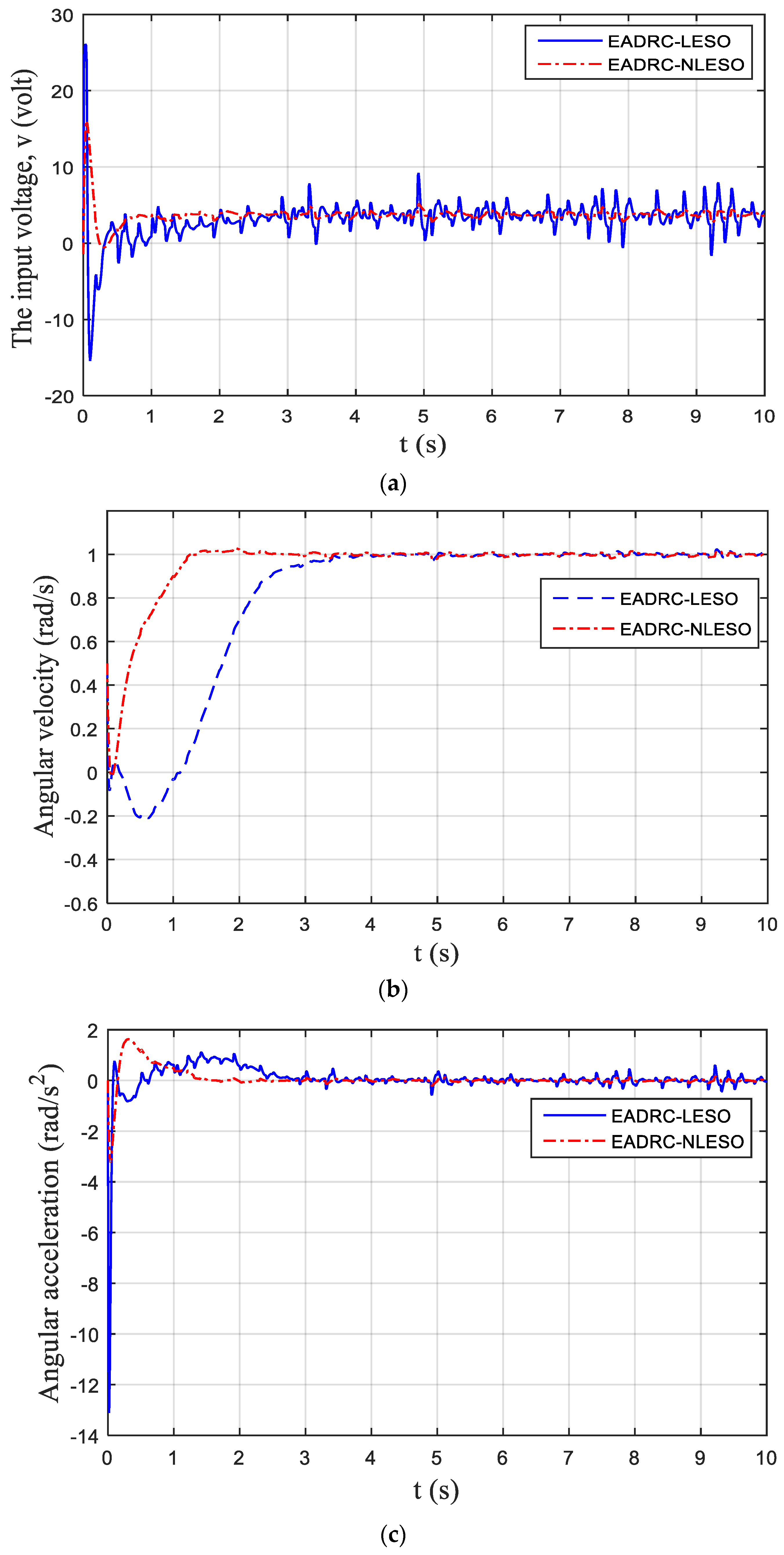
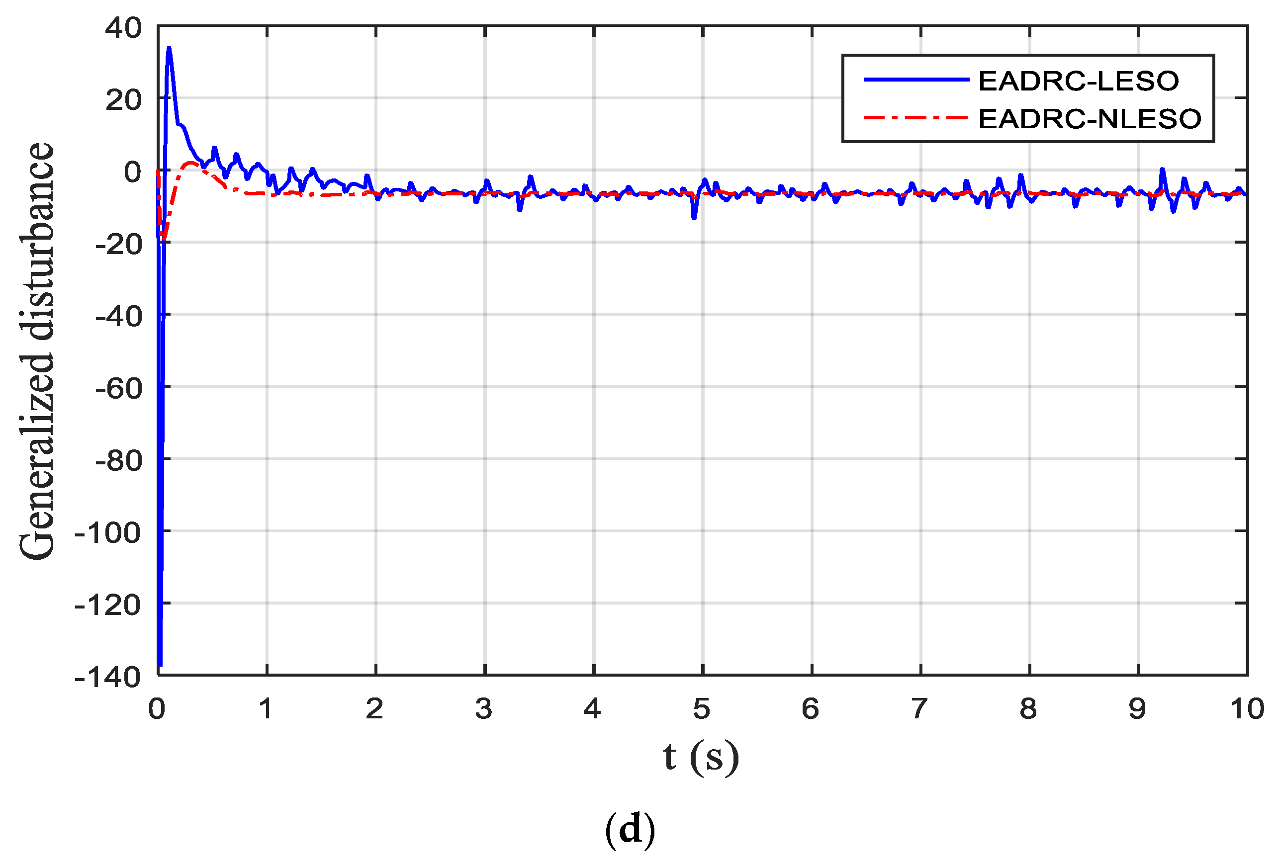
Another experiment has been conducted to test the proposed NLESO against measurement noise. Assume that y(t) has been contaminated by a Gaussian distributed random signal n(t),
y n ( t ) = y ( t ) + n ( t )
with 36 × 10 6 and zero mean and is added using MATLAB Simulink block called random number. With the same values of the parameters in the above simulations including the bandwidth ( ω o ), the results are presented in Figure 5. It can be seen that the noise still exists in the output response of the EADRC-LESO, while EADRC-NLESO produces a smoother response and suppresses noise evidently.
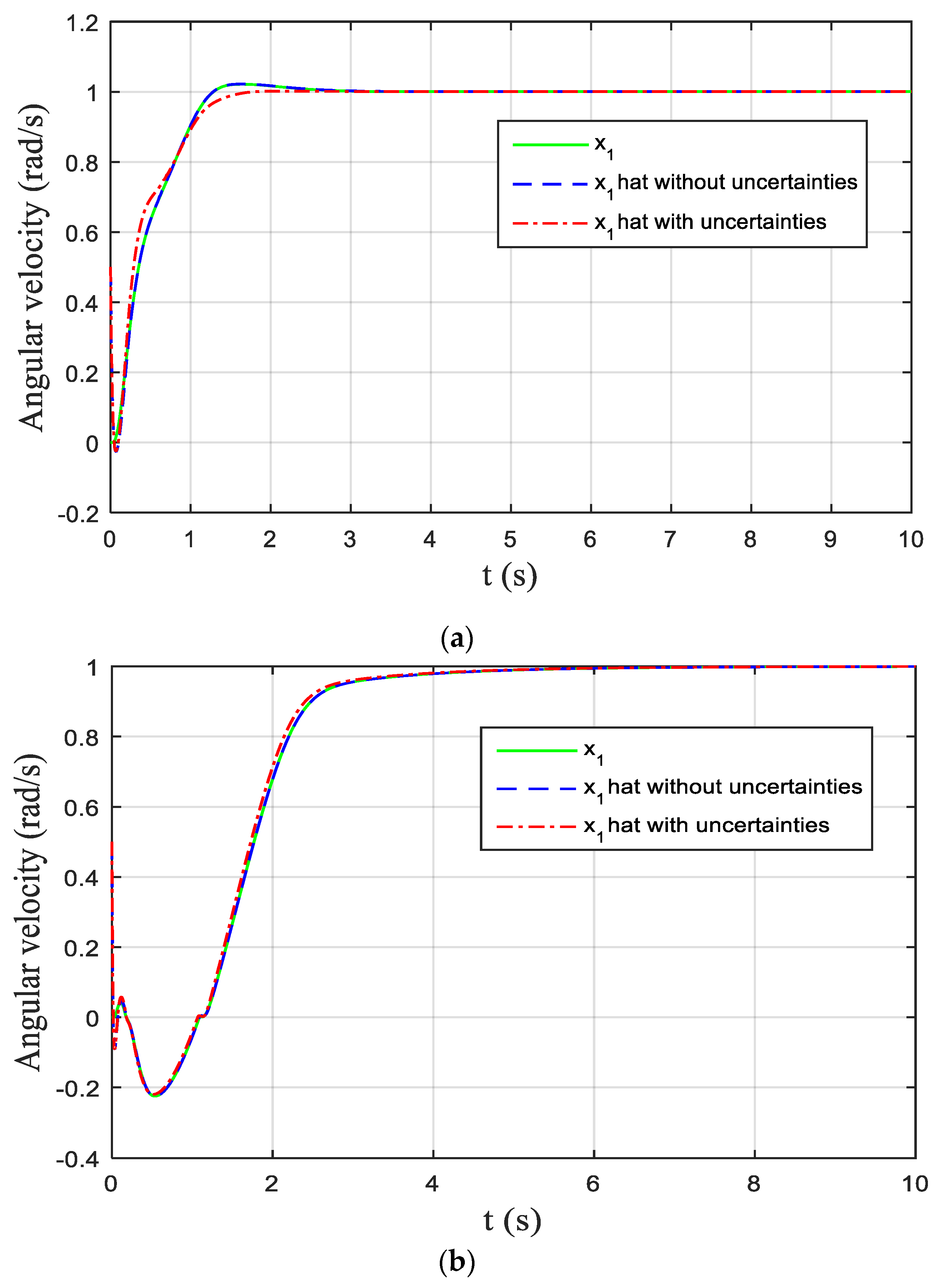
Finally, we end our simulations by subjecting the PMDC motor of (27) to parameter uncertainties and test the efficiency of EADRC-LESO, EADRC-NLESO, and compared to each other. The parameters to be varied are defined in their allowable range as follows,
J e q = J ¯ e q ( 1 + Δ J δ J )   ,   b e q = b ¯ e q ( 1 + Δ b δ b )   ,   R = R ¯ ( 1 + Δ R δ R )
where J ¯ e q = 0.275 ,   b ¯ e q = 0.392 , and R ¯ = 0.155 are called the nominal values of J e q , b e q , and Δ J , Δ b , and Δ R are the possible relative changes in their respective parameters. Assume that δ J = δ b = δ R = 1 and let Δ J = 0.2 , Δ b = 0.4 , and δ R = 0.5 ; the angular velocity of the PMDC motor of (39) using both EADRC-LESO and EADRC-NLESO are graphed in Figure 6.
To end this section, let us discuss the advantages and disadvantages of using NLESO over LESO in ADRC configuration. At steady state and for n = 2 , the error dynamics in (14) will be zero, i.e., e ˙ 1 ( t ) = e ˙ 2 ( t ) = e ˙ 3 ( t ) = 0 ; then, one can find a relationship between error e 1 ( t ) in the last equation of (14) in terms of Δ , β3, c3, and other parameters, e 1 ( t ) = φ ( Δ ,   β 3 , c 3 , ) , where φ ( . ) is a nonlinear function. The same can be done for e 2 ( t ) and e 3 ( t ) , i.e., e 2 ( t ) = γ ( Δ ,   β 2 , . ) , e 3 ( t ) = ϑ ( Δ ,   β 1 , . ) , and this makes the errors of the NLESO sensitive to Δ , which is the rate of the generalized disturbance L ( t ) , while in LESO, the errors are linearly depending on Δ . That explains the jumps in the generalized disturbance using EADRC-NLESO at the points in the times where L ( t ) exhibits a sudden increase or decrease (e.g., sudden external disturbance) or parameter variations in the nonlinear system of the PMDC motor described in (39). Figure 4a and Figure 6 clarify this reasoning.
Next, we comment on the peaking phenomenon in both EADRC-LESO and EADRC-NLESO scenarios; it occurs at the starting when there is an initial condition x ^ 1 ( 0 ) for x ^ 1 ( t ) different from that of x 1 ( t ) ( i . e . x ^ 1 ( 0 ) x 1 ( 0 ) ), this makes the terms in the equations of (14) that depends on ω o , i.e., a i ω 0 i 1   i ( ω 0 ( y ( t ) x ^ 1 ( t ) ) ) very large for some i ’s and with large ω 0 . This term with a large value in the right-hand side makes the ESO to produce large fluctuation on its output channels. For example, when i ( e ) = e , that means the ESO acts as a LESO, then the term a i ω 0 i 1   i ( ω 0 ( y ( 0 ) x ^ 1 ( 0 ) ) ) will have a high value for y ( 0 ) x ^ 1 ( 0 ) and large ω 0 . The nonlinear function of (11) in our proposed NLESO (10) has a saturation-like behaviour for large e1, in addition to the attenuating factors c i ( c 1 > c 1 > > c n + 1 ) , which explains why our proposed NLESO has a smaller peaking than LESO for the same ω 0 . For example, the ω 0 -dependent term in the i-th equation of (14) can be expressed as
a i ω 0 i 1 c i K α | ω 0 ( y ( 0 ) x ^ 1 ( 0 ) ) | α 1 ω 0 e 1 ( 0 ) + a i ω 0 i 1 c i K β | ω 0 ( y ( 0 ) x ^ 1 ( 0 ) ) | β ω 0 e 1 ( 0 )
The K β has small value in most cases as compared to K α , so for the easiness of illustration, we neglect the second term and the ω 0 -dependent becomes a i c i K α   ω 0 α + i 1 | ( y ( 0 ) x ^ 1 ( 0 ) ) | α 1 e 1 ( 0 ) , and since α + i 1 < i , then ω 0 α + i 1 < ω 0 i in the NLESO for big ω 0 . For example, assume ω 0 = 35 , α = 0.3 , n = 2, ρ = 2 , c 3 = 1 / 16 , K α = 0.99927 , and e 1 ( 0 ) = 1 , so | ( y ( 0 ) x ^ 1 ( 0 ) ) | = 1 . In the third equation (i = 3), a 3 = 1 and the ω 0 -dependent term, a i c i K α ω 0 2 + α e 1 ( 0 ) = 1 ×   1 16   × 0.99927 ×   ( 35 ) 2 + 0.3   ×   1   =   222.289 , whereas the corresponding term in the LESO is ( ω 0 ) 3   =   ( 35 ) 3   =   42,875 . The reduction in the peaking with the proposed saturation-like function i (.) defined in (11) in our proposed NLESO of (10) is noteworthy.
The same reasoning can be extended to illustrate why the noise is attenuated using our proposed NLESO of (10) with the saturation-like function i (.) defined in (11), where the noise is magnified to ( ω 0 ) 3 n ( t ) in the i-th equation of the LESO of (4). While with our proposed saturation-like function i (.) defined in (11), the magnification of the noise n ( t ) in our proposed NLESO of (10) is a i c i K α   ω 0 α + i 1 | ( y ( 0 ) x ^ 1 ( 0 ) ) | α 1 , which is proven to be less than ( ω 0 ) 3 . The results of Figure 5 illustrate this justification.

6. Conclusions

In this paper, a novel saturation-like function has been proposed and employed in the design of a nonlinear extended state observer used to estimate the states and the generalized disturbance of any uncertain nonlinear system with mismatch disturbance. Stability analysis based on Lyapunov principles has shown the asymptotic convergence of the proposed ESO and finite-time stability is always guaranteed provided that the generalized disturbance is bounded. The advantage of the proposed ESO is that it produced smaller peaking and had immunity against measurement noise and parameter variations. All the mathematical investigations and the conducted experiments included in this paper proved that the proposed ESO presented better performance than the linear ESO for the mentioned reasons. Employing the proposed ESO in the ADRC configuration provided an excellent tool to control any uncertain nonlinear system and to counteract the generalized disturbance. As a future direction, this work can be extended to a general MIMO uncertain nonlinear system and apply the proposed ESO to non-affine control system like ball-and-beam system.

Author Contributions

Investigation, A.J.H.; Supervision, I.K.I.

Funding

This research received no external funding.

Conflicts of Interest

The authors declare no conflict of interest.

Appendix A

Proof of Theorem 2
Differentiate the first equation of (23) w.r.t t along the dynamics of (22) one gets,
x ¨ 1 = f 1 ( x 1 , x 2 ) x 1 x ˙ 1 + f 1 ( x 1 , x 2 ) x 2 x ˙ 2 + b 1 d ˙
x ¨ 1 = f 1 ( x 1 , x 2 ) x 1 ( f 1 ( x 1 , x 2 ) + b 1 d ) + f 1 ( x 1 , x 2 ) x 2 ( f 2 ( x 1 , x 2 ) + b 2 u ) + b 1 d ˙ .
Rearrange (A2), then,
x ¨ 1 = f 1 ( x 1 , x 2 ) x 1 f 1 ( x 1 , x 2 ) + f 1 ( x 1 , x 2 ) x 2 f 2 ( x 1 , x 2 ) + b 2 f 1 ( x 1 , x 2 ) x 2 ( u + ( b 1 d ˙ + b 1 f 1 ( x 1 , x 2 ) x 1 d b 2 f 1 ( x 1 , x 2 ) x 2 ) ) .
Then, (A3) is reduced to
x ¨ 1 = f ^ ( x 1 , x 2 ) + b ^ ( u + d ^ )
Let, x ˜ 1 = x 1 x ˜ 2 = x ˙ 1 . Then,
{ x ˜ ˙ 1 = x ˜ 2   x ˜ ˙ 2 = f ^ ( x ˜ 1 , x ˜ 2 ,   x 2 ) + b ^ ( u + d ^ )   y = x ˜ 1   .
What remained is just x 2 , and one can find an expression of x 2 from the first equation of (22) and substitute this expression in (A4) to get a matched nonlinear state-space equation in terms of the new coordinate system x ˜ 1 , x ˜ 2 . Finally, (A4) is called the canonical form of ADRC (Brunovsky form) [1].

Appendix B

Conversion of nonlinear PMDC motor mismatched model into a Brunovsky form
Let x 1 = d θ d t   , x 2 = i , then, the mismatched nonlinear mathematical model of the PMDC motor can be written as
{ x ˙ 1 = 1 J e q ( K t x 2 T L b e q x 1 )   x ˙ 2 = 1 L ( R x 2 + v K b x 1 )    
Let
x ˜ 1 = x 1
x ˜ 2 = x ˙ 1 = 1 J e q ( K t x 2 T L b e q x 1 ) .
Then,
x ˜ ˙ 1 = x ˜ 2
x ˜ ˙ 2 = 1 J e q ( K t x ˙ 2 T ˙ L b e q x ˙ 1 ) .
Substituting (A5) into (A7), we get
x ˜ ˙ 2 = 1 J e q [ K t 1 L ( R x 2 + v K b x ˜ 1 ) T ˙ L b e q 1 J e q ( K t x 2 T L b e q x ˜ 1 ) ] = x 2 [ K t R J e q L + b e q K t J e q 2 ] + x ˜ 1 [ b e q 2 J e q 2 K t K b J e q L   ] + K t J e q L v + b e q J e q 2 T L 1 J e q T ˙ L .
To express (A8) in the new coordinate system ( x ˜ 1 , x ˜ 2 ) , we need to eliminate x 2 from (A8). From (A6),
x 2   = 1 K t ( J e q x ˜ 2 + T L + b e q x ˜ 1 ) .
Substituting (A9) in (A8), we have
x ˜ ˙ 2 = 1 K t ( J e q x ˜ 2 + T L + b e q x ˜ 1 ) [ K t R J e q L + b e q K t J e q 2 ] + x ˜ 1 [ b e q 2 J e q 2 K t K b J e q L   ] + K t J e q L v + b e q J e q 2 T L 1 J e q T ˙ L = R L x ˜ 2 R J e q L T L b e q R J e q L x ˜ 1 b e q J e q x ˜ 2 b e q J e q 2 T L b e q 2 J e q 2 x ˜ 1 + b e q 2 J e q 2 x ˜ 1 K t K b J e q L x ˜ 1 + K t J e q L v + b e q J e q 2 T L 1 J e q T ˙ L = R L x ˜ 2 R J e q L T L b e q R J e q L x ˜ 1 b e q J e q x ˜ 2 K t K b J e q L x ˜ 1 + K t J e q L v 1 J e q T ˙ L = ( R L + b e q J e q ) x ˜ 2 ( b e q R J e q L + K t K b J e q L ) x ˜ 1 + K t J e q L ( v + d )
where d = R K t T L L K t T ˙ L . So,
{ x ˜ ˙ 1 = x ˜ 2   x ˜ ˙ 2 = ( R L + b e q J e q ) x ˜ 2 ( b e q R J e q L + K t K b J e q L ) x ˜ 1 + K t J e q L ( v + d )
which is exactly the model given by (39) and the load torque is given as T L = T e x t + F c s g n ( x 1 ) .

References

  1. Guo, B.Z.; Zhao, Z.L. Active Disturbance Rejection Control for Nonlinear Systems: An Introduction, 1st ed.; John Wiley & Sons Singapore Pte. Ltd.: Singapore, 2016. [Google Scholar]
  2. Han, J. From PID to Active Disturbance Rejection Control. IEEE Trans. Ind. Electron. 2009, 56, 900–906. [Google Scholar] [CrossRef]
  3. Abdul-adheem, W.R.; Ibraheem, I.K. Improved Sliding Mode Nonlinear Extended State Observer based Active Disturbance Rejection Control for Uncertain Systems with Unknown Total Disturbance. Int. J. Adv. Comput. Sci. Appl. 2016, 7, 80–93. [Google Scholar]
  4. Qing, Z.; Gao, Z. On Practical Applications of Active Disturbance Rejection Control. In Proceedings of the Chinese Control Conference, Beijing, China, 29–31 July 2010; pp. 6095–6100. [Google Scholar]
  5. Abdul-Adheem, W.R.; Ibraheem, I.K. On The Active Input Output Feedback Linearization of Single Link Flexible Joint Manipulator, An Extended State Observer Approach. arXiv 2018, arXiv:1805.00222v1. [Google Scholar]
  6. Huang, Y.; Xue, W.; Gao, Z.; Sira-Ramirez, H.; Wu, D.; Sun, D. Active Disturbance Rejection Control: Methodology, Practice and Analysis. In Proceedings of the 33rd Chinese Control Conference, Nanjing, China, 28–30 July 2014; pp. 1–5. [Google Scholar] [CrossRef]
  7. Palli, G.; Strano, S.; Terzo, M. Sliding-mode observers for state and disturbance estimation in electro-hydraulic systems. Control Eng. Pract. 2018, 74, 58–70. [Google Scholar] [CrossRef]
  8. Strano, S.; Terzo, M. Accurate state estimation for a hydraulic actuator via a SDRE nonlinear filter. Mech. Syst. Signal Process. 2016, 75, 576–588. [Google Scholar] [CrossRef]
  9. Pappalardo, C.M.; Guida, D. Control of nonlinear vibrations using the adjoint method. Meccanica 2017, 52, 2503–2526. [Google Scholar] [CrossRef]
  10. Pappalardo, C.; Guida, D. Use of the Adjoint Method for Controlling the Mechanical Vibrations of Nonlinear Systems. Machines 2018, 6, 19. [Google Scholar] [CrossRef]
  11. Guo, L.; Cao, S. Anti-disturbance control theory for systems with multiple disturbances: A survey. ISA Trans. 2014, 53, 846–849. [Google Scholar] [CrossRef]
  12. Radke, A.; Gao, Z. A survey of state and disturbance observers for practitioners. In Proceedings of the 2006 American Control Conference, Minneapolis, MN, USA, 14–16 June 2006; pp. 5183–5188. [Google Scholar] [CrossRef]
  13. Tian, G.; Gao, Z. From Poncelet’s invariance principle to Active Disturbance Rejection. In Proceedings of the 2009 American Control Conference, St. Louis, MO, USA, 10–12 June 2009; pp. 2451–2457. [Google Scholar] [CrossRef]
  14. Johnson, C.D. Accommodation of External Disturbances in Linear Regulator and Servomechanism Problems. IEEE Trans. Autom. Control 1973, 16, 635–644. [Google Scholar] [CrossRef]
  15. Umeno, T.; Hori, Y. Robust Speed Control of DC Servomotors Using Modern Two Degrees-of-Freedom Controller Design. IEEE Trans. Ind. Electron. 1991, 38, 363–368. [Google Scholar] [CrossRef]
  16. Kwon, S.J.; Chung, W.K. Robust performance of the multiloop perturbation compensator. IEEE/ASME Trans. Mechatron. 2002, 7, 190–200. [Google Scholar] [CrossRef]
  17. Gao, Z. Active disturbance rejection control: A paradigm shift in feedback control system design. In Proceedings of the American Control Conference, Minneapolis, MN, USA, 14–16 June 2006; pp. 2399–2405. [Google Scholar] [CrossRef]
  18. Najm, A.A.; Ibraheem, I.K. On The Design of Nonlinear PID Controller for Nonlinear Quadrotor System. Eng. Sci. Technol. 2019. [Google Scholar] [CrossRef]
  19. Maher, R.A.; Mohmmed, I.A.; Ibraheem, I.K. State-Space Based H∞ Robust Controller Design for Boiler-Turbine System. Arab. J. Sci. Eng. 2012, 37, 1767–1776. [Google Scholar] [CrossRef]
  20. Ibraheem, I.K. A Digital-Based Optimal AVR Design of Synchronous Generator Exciter Using LQR Technique. Al-Khwarizmi Eng. J. 2011, 7, 82–94. [Google Scholar]
  21. Ibraheem, I.K.; Ibraheem, G.A. Motion Control of An Autonomous Mobile Robot using Modified Particle Swarm Optimization Based Fractional Order PID Controller. Eng. Technol. J. 2016, 34, 2406–2419. [Google Scholar]
  22. Ibraheem, I.K. Robust Governor Design for Hydro machines using H∞ Loop-Shaping Techniques. In Proceedings of the 6th Engineering Conference, Baghdad, Iraq, 5–7 April 2009; pp. 1–10. [Google Scholar]
  23. Ibraheem, I.K. On the frequency domain solution of the speed governor design of non-minimum phase hydro power plant. Mediterr. J. Meas. Control 2012, 8, 422–429. [Google Scholar]
  24. Guo, B.Z.; Zhao, Z.-L. On convergence of non-linear extended state observer for multi-input multi-output systems with uncertainty. IET Control Theory Appl. 2012, 6, 2375–2386. [Google Scholar] [CrossRef]
  25. Huang, Y.; Xue, W. Active disturbance rejection control: Methodology and theoretical analysis. ISA Trans. 2014, 53, 963–976. [Google Scholar] [CrossRef]
  26. Pu, Z.; Yuan, R.; Yi, J.; Tan, X. A Class of Adaptive Extended State Observers for Nonlinear Disturbed Systems. IEEE Trans. Ind. Electron. 2015, 62, 5858–5869. [Google Scholar] [CrossRef]
  27. Bao, D.; Tang, W. Adaptive sliding mode control of ball screw drive system with extended state observer. In Proceedings of the 2nd International Conference on Control, Automation and Robotics (ICCAR), Hong Kong, China, 19–22 April 2016; pp. 133–138. [Google Scholar] [CrossRef]
  28. Godbole, A.A.; Kolhe, J.P.; Talole, S.E. Performance analysis of generalized extended state observer in tackling sinusoidal disturbances. IEEE Trans. Control Syst. Technol. 2013, 21, 2212–2223. [Google Scholar] [CrossRef]
  29. Li, J.; Qi, X.; Xia, Y.; Pu, F.; Chang, K. Frequency domain stability analysis of nonlinear active disturbance rejection control system. ISA Trans. 2014, 56, 1–8. [Google Scholar] [CrossRef]
  30. Li, J.; Xia, Y.; Qi, X.; Gao, Z. On the Necessity, Scheme, and Basis of the Linear-Nonlinear Switching in Active Disturbance Rejection Control. IEEE Trans. Ind. Electron. 2017, 64, 1425–1435. [Google Scholar] [CrossRef]
  31. Mao, J.; Gu, L.; Wu, A.; Wu, G.; Zhang, X.; Chen, D. Back-stepping Control for Vertical Axis Wind Power Generation System Maximum Power Point Tracking based on Extended State Observer. In Proceedings of the 35th Chinese Control Conference, Chengdu, China, 27–29 July 2016; pp. 8649–8653. [Google Scholar] [CrossRef]
  32. Yang, H.; Yu, Y.; Yuan, Y.; Fan, X. Back-stepping control of two-link flexible manipulator based on an extended state observer. Adv. Space Res. 2015, 56, 2312–2322. [Google Scholar] [CrossRef]
  33. Huang, Y.; Han, J. Analysis and design for the second order nonlinear continuous extended states observer. Chin. Sci. Bull. 2000, 45, 1938–1944. [Google Scholar] [CrossRef]
  34. Bhat, S.P.; Bernstein, D.S. Finite-time stability of homogeneous systems. In Proceedings of the 1997 American Control Conference (Cat. No. 97CH36041), Albuquerque, NM, USA, 6 June 1997; Volume 4, pp. 2513–2514. [Google Scholar]
  35. Bhat, S.P.; Bernstein, D.S. Finite-Time Stability of Continuous Autonomous Systems. SIAM J. Control Optim. 2000, 38, 751–766. [Google Scholar] [CrossRef] [Green Version]
  36. Bhat, S.P.; Bernstein, D.S. Continuous finite-time stabilization of the translational and rotational double integrators. IEEE Trans. Autom. Control 1998, 43, 678–682. [Google Scholar] [CrossRef]
  37. Levant, A. Higher-order sliding modes, differentiation and output-feedback control. Int. J. Control 2003, 76, 924–941. [Google Scholar] [CrossRef]
  38. Filippov, A.F. Differential Equations with Discontinuous Right Hand Side; Springer: Berlin/Heidelberg, Germany, 1988. [Google Scholar]
  39. Yi, H.; Jingqing, H. The self-stable region approach for second order nonlinear uncertain systems. In Proceedings of the IFAC 14th Triennial World Congress, Beijing, China, 5–9 July 1999; Volume 32, pp. 2262–2267. [Google Scholar] [CrossRef]
  40. Guo, B.Z.; Wu, Z.H. Output tracking for a class of nonlinear systems with mismatched uncertainties by active disturbance rejection control. Syst. Control Lett. 2017, 100, 21–31. [Google Scholar] [CrossRef]
  41. Khalil, H.K. Nonlinear Systems, 3rd ed.; Prentice Hall: Upper Saddle River, NJ, USA, 2002. [Google Scholar]
  42. Isidori, A. Nonlinear Control Systems; Springer Science & Business Media: Berlin/Heidelberg, Germany, 2013. [Google Scholar]
  43. Li, S.; Yang, J.; Chen, W.H.; Chen, X. Generalized extended state observer based control for systems with mismatched uncertainties. IEEE Trans. Ind. Electron. 2012, 59, 4792–4802. [Google Scholar] [CrossRef]
  44. Abdul-Adheem, W.R.; Ibraheem, I.K. A Novel Second-Order Nonlinear Differentiator With Application to Active Disturbance Rejection Control. In Proceedings of the the 1st International Scientific Conference of Engineering Sciences and the 3rd Scientific Conference of Engineering Sciences, Diyala, Iraq, 10–11 January 2018; pp. 68–73. [Google Scholar]
  45. Abdul-Adheem, W.R.; Ibraheem, I.K. From PID to Nonlinear State Error Feedback Controller. Int. J. Adv. Comput. Sci. Appl. 2017, 8, 312–322. [Google Scholar]
  46. Humaidi, A.J. Experimental Design and Verification of Extended State Observers for Magnetic Levitation System Based on PSO. Open Electr. Electron. Eng. J. 2018, 12, 110–120. [Google Scholar] [CrossRef]
  47. Humaidi, A.J.; Badr, H.M.; Hameed, A.H. PSO-Based Active Disturbance Rejection Control for Position Control of Magnetic Levitation System. In Proceedings of the IEEE 5th International Conference on Control, Decision and Information Technologies (CoDIT’18), Thessaloniki, Greece, 10–13 April 2018; pp. 922–928. [Google Scholar]
  48. Humaidi, A.J.; Badr, H.M.; Ajil, A.R. Design of Active Disturbance Rejection Control for Single-Link Flexible Joint Robot Manipulator. In Proceedings of the IEEE 22nd International Conference on System Theory, Control and Computing (ICSTCC) Design, Sinaia, Romania, 10–12 October 2018; pp. 452–457. [Google Scholar]
  49. Humaidi, A.J.; Badir, H.M. Linear and Nonlinear Active Disturbance Rejection Controllers for Single-Link Flexible Joint Robot Manipulator based on PSO Tuner. J. Eng. Sci. Technol. Rev. 2018, 11, 133–138. [Google Scholar] [CrossRef]
  50. Sun, Y.H.; Chen, T.; Wu, C.Q.; Shafai, C. A comprehensive experimental setup for identification of friction model parameters. Mech. Mach. Theory 2016, 100, 338–357. [Google Scholar] [CrossRef]
  51. Mahfouz, A.A.; Salem, F.A. Mechatronics Design of a Mobile Robot System. Int. J. Intell. Syst. Appl. 2013, 3, 23–36. [Google Scholar] [CrossRef]
Figure 1. Schematic diagram of the permanent magnet DC (PMDC) motor.
Energies 12 01651 g001
Figure 2. Results of the numerical simulations of the PMDC motor by enhanced active disturbance rejection control (EADRC)-nonlinear extended state observer (NLESO).
Energies 12 01651 g002aEnergies 12 01651 g002b
Figure 3. Results of the numerical simulations of the PMDC motor by EADRC-linear extended state observer (LESO).
Energies 12 01651 g003aEnergies 12 01651 g003b
Figure 4. Angular velocity due to an external step disturbance of 2 N.m.
Energies 12 01651 g004aEnergies 12 01651 g004b
Figure 5. The numerical results for PMDC motor of Equation (27) with measurement noise.
Energies 12 01651 g005aEnergies 12 01651 g005b
Figure 6. The angular velocity of PMDC motor of Equation (27) with parameter uncertainties.
Energies 12 01651 g006