1. Introduction
With the rapid development of hydropower, safe and stable operation is becoming increasingly important. In addition, as renewable energies, such as wind power and solar power, are being incorporated into electric grids, the hydropower units require higher flexibility and stability. Consequently, hydropower units often operate under off-design conditions [
1,
2]. Cavitation and high-amplitude pressure fluctuations are two of the most severe stability problems under off-design conditions. They are greatly harmful to the stability of Francis turbines and even the whole hydraulic system [
3,
4]. Hence, studies on the generation mechanism and methods to restrain the occurrence of cavitation and reduce of high-amplitude pressure fluctuation are valuable.
The instabilities caused by cavitation and pressure fluctuation have been studied for many years, and a great number of achievements have been accomplished through experimental and numerical methods. Wang et al. [
5] performed numerical simulations to study the pressure fluctuation in a large Francis turbine runner and concluded that the characteristic frequencies are affected by the flow in the guide vanes and draft tube. Li et al. [
6] found, through numerical methods, that the amplitudes of pressure fluctuations in the vaneless space in a pump-turbine are strongly influenced by the oscillation of the guide vanes. Zuo et al. [
7] analyzed the pressure fluctuations induced by interblade vortices in a model Francis turbine and estimated the stability of these interblade vortices using the centrifugal Rayleigh instability criterion. Amiri et al. [
8] addressed the unsteady pressure measurements for the blades and stationary parts of a Kaplan turbine model during load acceptance and rejection transient processes and revealed the effect of load variation on the pressure distributions in the turbine. Trivedi et al. [
9] conducted transient pressure measurements on a high-head model Francis turbine during emergency shutdown, total load rejection, and runaway, and they observed the maximum amplitudes of unsteady pressure fluctuation in the turbine under the runaway condition. Li et al. [
10] carried out a numerical simulation to study the mechanism of high-amplitude low-frequency fluctuations under large partial operating conditions in a Francis pump-turbine in pump mode. The results show that the high-amplitude pressure fluctuation at 0.74
QBEP originates from the rotation of Dean vortices in the draft tube.
All the above studies enable a deep understanding of the variation in pressure fluctuation and its formation mechanism. However, few methods for restraining the occurrence of cavitation and reducing high-amplitude pressure fluctuation have been reported.
Li et al. [
11] concluded from a numerical simulation that the number of runner blades could change the dominant characteristics of pressure fluctuation. Yang et al. [
12] found that the unsteady pressure field within a pump is improved when the turbine used splitter blades. Lin et al. [
13] conducted a numerical analysis on a conventional runner and a runner with splitter blades, and they concluded that the runner with splitter blades could improve the inflow condition of the runner, and thereby increase the operation stability and energy characteristics. Hou et al. [
14] performed simulations for an ultra-high-head Francis runner with splitter blades of different length ratios and found that the efficiency was much higher when the length ratio was between 60% to 75%. Kergourlay et al. [
15] studied the influence of splitter blades on the performance of a centrifugal pump, using numerical simulation, and the results revealed that the splitter blades could decrease the pressure fluctuation at the canal duct.
In summary, splitter blades can effectively improve the performance characteristics. This study aimed to determine the effects of splitter blades on the performance characteristics of a Francis turbine. Hence, experimental studies on the energy characteristics, cavitation, and pressure fluctuation were carried out. The experimental results of Francis turbines with splitter blades and normal blades were compared. Detailed comparative analyses of the efficiency, occurrence of cavitation, variation in peak-to-peak amplitude, and frequency domain under the operating conditions were conducted. Herein, firstly, a brief introduction on the related experimental information, including a description of the test rig, flow pattern observation system, and Francis specifications is provided. Then, the results of the comparative analyses of the efficiency, occurrence of the cavitation at suction side of the blades, and pressure fluctuations of the two different runners under various operating conditions are performed. Finally, a detailed discussion about the effect of splitter blades on the characteristics of the Francis turbine is presented.
2. Experimental Information
2.1. Francis Turbine Specification
The investigated turbine was a Francis turbine. The rated head was 202 m for the prototype turbine. The Francis turbine was composed of one runner with 15 blades, 24 guide vanes, 23 stay vanes, one draft tube, and one spiral casing. Based on the above parameters, splitter blades were designed to replace the normal blades. The new runner included 15 long blades and 15 short blades. The shape and total size of the long blades were the same as those of the old runner. A sketch of the two runners is shown in
Figure 1. The main parameters of the two runners are listed in
Table 1. The different views of the two runners are shown in
Figure 2.
2.2. Test Rig
All the experiments were carried out at the Harbin Institute of Large Electrical Machinery (HILEM). There are six test rigs in HILEM, that can conduct performance characteristic, pressure fluctuation, and cavitation experiments on different types of turbines and pumps. The experiments for this study were carried out in test rig number 3 shown in
Figure 3. The main parameters are listed in
Table 2. The test rig is a closed-loop system, as shown in
Figure 4, which can operate in two directions. The acquisition system was programmed using LabVIEW 2015 (National Instruments, Austin, Texas, USA). All the experiments met the standard of the International Electrotechnical Commission (IEC60193) [
16].
2.3. Performance Characteristic Measurements
Performance characteristics (head, torque and efficiency) could be measured using the test rig. The hydraulic torque of the runner was measured by an 1110-A0-1K torque sensor, manufactured by the Interface Inc. (Scottsdale, Arizona, USA, Range: 0–1000 p; Accuracy: ±0.02%). The rotational speed was measured by the rotational speed sensor (MP-981, made by ONOSOKKI (Yokohama, Japan; Range: 0–3000 r/min; Accuracy: ±0.06%). The head of the turbine was measure using a pressure difference sensor (3051CD4A22A1A, Rosemount, 1110-A0-1K torque sensor, Range: 0–2.07 MPa; Accuracy: ±0.075%). The discharge was measured by the discharge sensor, which was manufactured by Rosemount (8732E, Range: 0–1.2 m
3/s; Accuracy: ±0.15%). All the sensors were calibrated before the measurements according to the standard of the International Electrotechnical Commission (IEC60193) [
16].
2.4. Flow Pattern Observation System
The flow patterns of the test rig could be observed, recorded, and photographed using a light-guide endoscope-stroboscope from DRELLO (Nürnberg, Germany), an optical fiber endoscope from Wolf (Mainburg, Bavaria, Germany), and an image monitoring system, as shown in
Figure 5. Using this device, the front and back flow and the vortex cavitation of runner blades can be observed. In addition, it can also be used to observe Karman vortices, interblade vortices, and the vortex rope at the runner outlet.
The image monitoring system uses a high-definition high-resolution industrial camera as the core, and employs a manual-zoom telescope objective lens to achieve high-definition imaging.
The image monitoring system consists of three high-resolution industrial digital cameras (GC1020C, Allied Vision, Stradtroda, Thuringia, Germany) that form the front-end imaging part. The shooting of the digital camera is controlled by the back-end computer. The aperture and shutter can be programmed. Synchronous or asynchronous imaging can be conducted with the stroboscope. The image taken was displayed on the back-end computer screen, the display screen of the model segment, and a HDTV in the conference room.
The Wolf endoscope used was manufactured by. The endoscope specifications were φ10 mm × 300 mm × DOV 50° × FO55, 10 mm diameter, 300 mm working length, 50° viewing angle, and 55° field of view; the optical lens system of the industrial rigid endoscope adopts the “lupus-telescope” technology, glass fiber illumination, and a rotary light-guide joint, which can rotate 360°. The system is heat resistant up to 135 °C and a pressure of 4 bar.
The stroboscope used was a Dreloscope 3020C (Digital display: 5-digit, 7-segment LED display, 12 mm high; Angle display: 5 digits, angular resolution better than 0.1°; Flash energy: up to 7.5 jog/flash; Lighting area: 3000 mm in the range of 2 m; Lighting: 4037 hand-held light with mirror (6 m long connection cable); Flash intensity: greater than 10,000 lux).
2.5. Pressure-Fluctuation Experiments
To investigate the effects of the splitter blades on the pressure fluctuation, pressure-fluctuation experiments were conducted for both types of blades. In these experiments, 11 high-resolution pressure sensors (PCB-S112A22, PCB Piezotronics, New York, USA: Voltage sensitivity, 14.20 mV/kPa; Output bias level, 9.5 V DC) were mounted throughout the Francis turbine. As shown in
Figure 6, one is in the spiral casing (SC1), four are in the vanless space between the guide vane and the runner (RG1, RG2, RG3, and RG4), four are in the cone of the draft tube (CT1, CT2, CT3, and CT4), and two are in the elbow of the draft tube (ET1 and ET2). All the pressure sensors were calibrated before the experiments, and the errors of the fitting were within 0.4%. All the experiments were carried out at a fixed head (25 m). The sampling rate was set as 4000 Hz, and the number of sample points was 40,000 for every operating point, i.e., it took 10 s to finish the acquisition for each point. The frequency resolution was 0.1 Hz, which was high enough to capture the low frequency induced by the motion of unsteady vortices and the blade-passing frequency, as well as the harmonic frequencies originating from the rotor–stator interaction.
3. Results and Discussion
3.1. Effects on Efficiency
The normal operating conditions of prototype turbines are constant rotational speeds under different heads. Generally, in model Francis turbine experiments, the rotational speed is changed at a constant head to simulate different operating conditions of prototype Francis turbines. The rated head of the investigated Francis turbine was 202 m, and the maximum and minimum heads were 243 and 164 m, respectively.
To evaluate the effect of the splitter blades on the efficiency, a comparison of the efficiencies under different heads was conducted, as shown in
Figure 7. In this study, the discharge factor and efficiency are calculated according to Equations (1) and (2):
where
D1 is the diameter of the runner inlet, m;
n is the rotational speed of the runner, r/min;
g is the gravitational acceleration, m/s
2;
H is the head, m;
Qm is the mass flow, kg/s; and
T is the hydraulic torque of the runner, N·m.
At the maximum head (243 m), when the discharge factor was less than 0.14, the efficiency evidently increased for the runner with splitter blades (approximately 2%), whereas when the discharge factor was higher than 0.45, there was no evident change in the efficiency for the splitter blades compared with that for the normal blades. At a 220 m head, when the discharge factor was less than 0.12, the efficiency for the splitter blades was higher than that for the normal blades. When the discharge factor was higher than 0.12, the efficiencies for the two types of blades were almost the same. At the rated head (202 m), the efficiencies for both the types of blades were nearly the same for most operating conditions, except one operating point. At that point, the efficiency for the splitter blades was slightly lower than that for the normal blades. At a 164 m head, when the discharge factor was between 0.06 and 0.14, the efficiency for the splitter blades was lower than that for the normal blades. Under the other operating conditions, the efficiencies for the two types of blades were the almost the same.
It can be concluded that under the high-head operating conditions, the splitter blades can increase the efficiency. Under the rated-head operating conditions, the efficiency does not change. However, under low-head operating conditions, the efficiency for the splitter blades certainly decreases.
3.2. Effects on Cavitation Ability
In Francis turbines operating under off-design conditions, cavitation may occur on the suction side of the blades, which restrains the stable operating range. In the hill diagram using unit parameters between the cavitation and non-cavitation regions, there is a line named the incipient cavitation line, which is the criterion for the cavitation ability of Francis turbines.
To study the effect of the splitter blades on the cavitation ability, hill diagrams using the parameters (
QED, discharge factor;
nED, speed factor) of the two types of blades were plotted as depicted in
Figure 8 and
Figure 9. In these figures, the ab line represents the incipient cavitation line for the suction side of the blades. At the low unit rotational speed and high unit discharge region, the cavitation ability improved evidently. This indicates that the safe and stable operating range expands upon using splitter blades.
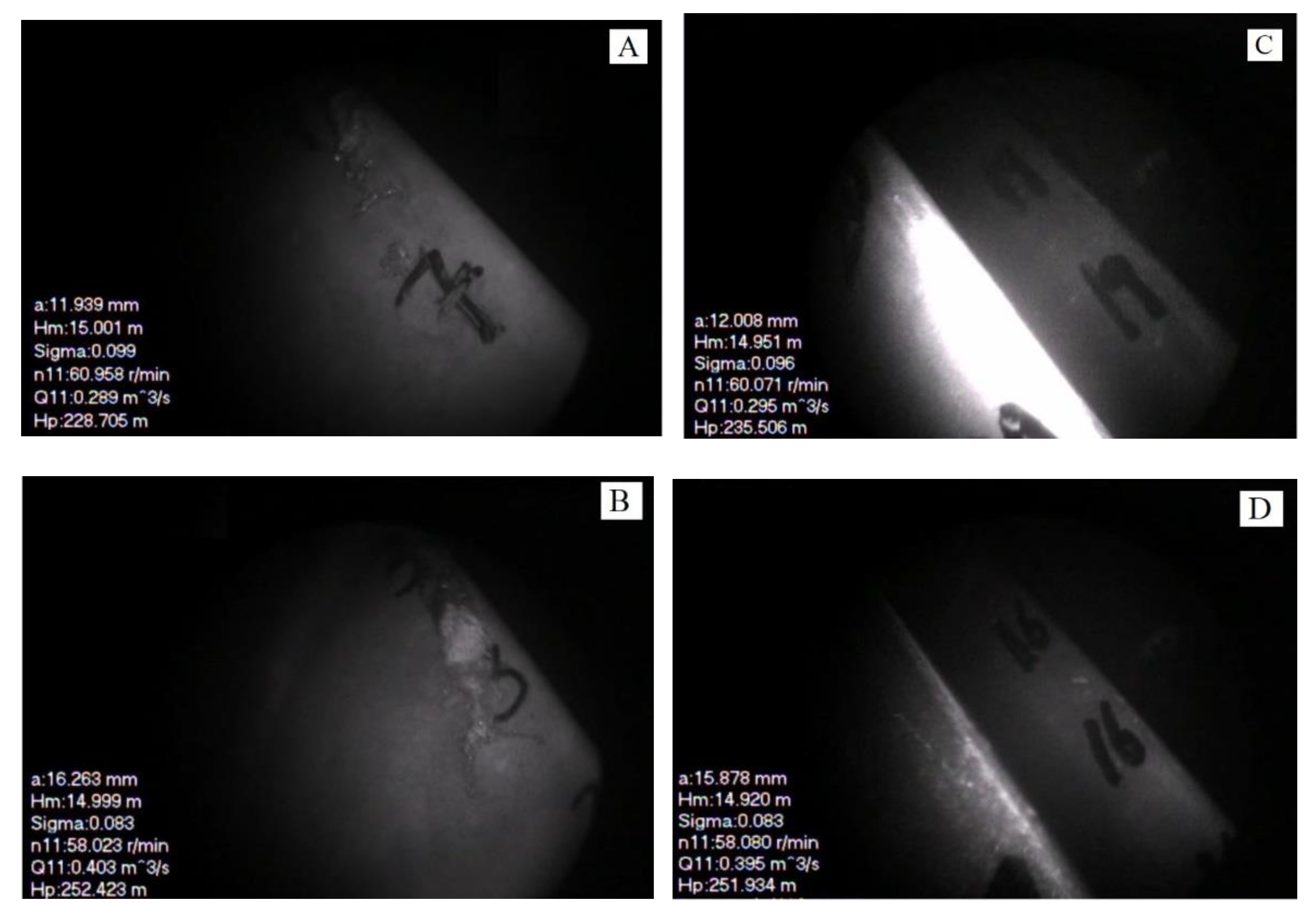
Four operating points (A:
nED = 19.5;
QED = 0.946; B:
nED = 18.5;
QED = 0.130; C:
nED = 19.1;
QED = 0.960; D:
nED = 18.5;
QED = 0.126) were chosen to observe the flow patterns at the suction sides of the blades shown in in
Figure 10. Using
Figure 10A, evident cavitation was found at the suction side of the blades at point A for the normal blades. There was no evident cavitation at almost the same operating point C for the splitter blades. At operating point B for the normal blades, which was located in the cavitation region, severe cavitation could be observed at the suction sides; whereas, at the operating point D for the splitter blades, which was located in the non-cavitation region, no cavitation could be observed. Therefore, the splitter blades could evidently improve the cavitation ability under off-design operating conditions.
3.3. Effects on Pressure Fluctuation
3.3.1. Comparison of amplitude of pressure fluctuation
In this study, all the signals from the experiments are normalized according to Equation (3):
where Δ
Cp indicates the peak-to-peak value for the pressure fluctuation of the pressure–time signal. In this study, Δ
Cp was used to denote the relative value of the pressure fluctuation.
The peak-to-peak values for different components under different discharge operating conditions at maximum head (243 m) are depicted in
Figure 11. The amplitudes of pressure fluctuations for both the runners in the Francis turbine increase as the discharge increases. The highest amplitude of pressure fluctuation is that for the cone of the draft tube.
In the spiral casing, for most operating conditions, the runner with splitter blades could reduce the peak-to-peak value. The maximum decrease in peak-to-peak value of the pressure was 0.64, from 0.98 to 0.34 (65.3%) at analysis point A. In the vaneless space between the guide vanes and the runner, for most operating conditions, the splitter blades could evidently reduce the pressure fluctuations. The maximum decrease in peak-to-peak value of the pressure was 1.25, from 2.15 to 0.90 (58.1%) at analysis point A. In this space, pressure fluctuations mainly arise from the rotor–stator interaction. This indicates that the splitter blades evidently improve the rotor–stator interaction, as proved in the following section. For the draft tube, the peak-to-peak values at all the operating conditions are almost same for the runners with splitter blades and normal blades. In the draft tube, pressure fluctuations mainly originate from the vortex rope. This reveals that the splitter blades have no effect on the generation of the vortex rope, as discussed in the following section.
3.3.2. Influence of head on pressure fluctuation
To investigate the influence of the head on the pressure fluctuation, the peak-to-peak values for different positions under different heads were determined as shown in
Figure 12,
Figure 13,
Figure 14 and
Figure 15. The peak-to-peak values for the spiral casing at different heads are shown in
Figure 12. The amplitudes of the pressure fluctuation show a slight decline as the head decreases from 220 to 185 m. As the head continues to decrease to 164 m, the amplitudes of the pressure fluctuation at large discharge operating conditions evidently increase. Furthermore, the splitter blades could reduce the pressure fluctuation at the at large discharge under low-head operating conditions. Whereas, the splitter blades do not improve the pressure fluctuations in the spiral casing around the rated operating conditions. The variations in the peak-to-peak values for the vaneless space are shown in
Figure 14. The amplitudes of the pressure fluctuation at the rated head (202 m) are the smallest, and there are no evident differences in the peak-to-peak values for both the runners. Under the high-head operating conditions (220 m), the runner with splitter blades evidently reduces the pressure fluctuation, unlike the runner with normal blades. Under the low-head operating conditions (185 m and 164 m), the pressure fluctuation at a large discharge increases sharply. The splitter blades could reduce the pressure fluctuation in the vaneless space, unlike the normal blades.
The peak-to-peak values for the cone of the draft tube at different heads are shown in
Figure 14. This figure shows that the pressure fluctuation under off-design operating conditions is evidently higher than that under other operating conditions. At heads of 202 m and 164 m, the splitter blades evidently reduce the pressure fluctuation under large-discharge operating conditions. However, under other operating conditions, the splitter blades have no differences compared with the normal blades. The peak-to-to peak values for the elbow of the draft tube at different heads are depicted in
Figure 15. The variations in these peak-to-peak values are almost the same as those for the cone of the draft tube.
3.3.3. Analysis of main frequencies
To analyze the effects of splitter blades on the main frequencies, a fast Fourier transform was applied to certain monitoring points. According to the above analysis, under 243 m head operating condition, the splitter blades evidently reduce the pressure fluctuation when
QED = 0.1–0.16. Hence, operating point
QED = 0.126 (Analysis point A) was chosen to perform detailed frequency analysis. The frequency characteristics in the spiral casing with normal and splitter blades are shown in
Figure 16. There are no high-amplitude main frequencies could be observed. The frequency characteristics in the vaneless space are shown in
Figure 17. In the vaneless space with splitter blades, the main frequency is 30
fn (where
fn is the rotating frequency of the runner); whereas, for normal blades, the first frequency is 15
fn, which are both blade passing frequencies originating from the rotor–stator interaction. The amplitude of pressure fluctuation induced by rotator–stator interaction was reduced by 71.4% from 0.311 to 0.089. In addition, rotating frequency (1.0
fn) and its harmonic frequency (2.0
fn) for both blades could be found. The rotating frequency and its harmonic frequencies increased slightly. However, the increase is relatively lower as compared with that in the blade passing frequency. The splitter blades change the main frequency and sharply decrease its amplitude. Based on the above analysis, the splitter blades decrease the pressure fluctuation in the vaneless space. It can be concluded that the runner with more splitter blades than normal blades changes the blade-passing frequency and significantly lowers the effects of the rotator–stator interaction.
The frequency characteristics in the cone of the draft tube are depicted in
Figure 18. For normal blades, the first main frequency is 1.536
fn, whereas it is 1.416
fn for the splitter blades. Frequencies 1.536
fn and 1.416
fn, were usually from the rotation of vortex rope in the draft tube [
16]. The amplitude of the first main frequency increased a certain degree upon using splitter blades. The frequency characteristics in the elbow of the draft tube are shown in
Figure 19. The first main frequency is 1.536
fn with normal blades, whereas it is 1.416
fn for splitter blades. The amplitude induced in a slight degree, the difference between the two frequencies is small. According to the analysis results in
Section 3.3.2, the pressure fluctuation in the cone of the draft tube is relatively low. In addition, the splitter blades have no effective function compared with normal blades.
According to the analysis results in
Section 3.3.2, as the head reduces, the effects of the splitter blades on the pressure fluctuation decrease. However,
Figure 13 shows that the splitter can lower the pressure fluctuation in the vaneless space for the
QED = 0.16–0.20 under the low-head operating condition (164 m). Hence, the operating point
QED = 0.177 (Analysis point B) was chosen to perform detailed frequency analyses.
Figure 20 gives the frequency characteristics in the vaneless space at a 164 m head. The first main frequency is 15
fn with a high amplitude for normal blades, whereas it is 1.0
fn for the splitter blades. In addition, the harmonic frequencies of the rotating frequency (2
fn, 3
fn) could be found. The amplitudes of these frequencies have no significant change. The splitter blades mainly change the frequency induced by the rotator–stator interaction and lower its amplitude.
Figure 21 shows the frequency characteristics in the cone of the draft tube at a 164 m head. Under the off-design operating conditions, high-amplitude low frequencies could be observed, which are generally from the rotation of the vortex rope in the draft tube. Based on the frequency analysis, it can be concluded that the splitter blades may change the rotation of vortex rope. Numerical simulation needs to be conducted to investigate the effect and its mechanism in detail.


