Article

Flexible Modern Power System: Real-Time Power Balancing through Load and Wind Power

1
US Pakistan Center for Advance Studies in Energy, University of Engineering and Technology, 25000 Peshawar, Pakistan
2
Department of Wind Energy, Technical University of Denmark, 2800 Lyngby, Denmark
3
KIOS Research and Innovation Center of Excellence, Department of Electrical and Computer Engineering, University of Cyprus, 1678 Nicosia, Cyprus
*
Author to whom correspondence should be addressed.
Energies 2019, 12(9), 1710; https://doi.org/10.3390/en12091710
Submission received: 12 March 2019 / Revised: 10 April 2019 / Accepted: 25 April 2019 / Published: 6 May 2019

Abstract

:
Increasing large-scale integration of renewables in conventional power system has led to an increase in reserve power requirement owing to the forecasting error. Innovative operating strategies are required for maintaining balance between load and generation in real time, while keeping the reserve power requirement at its minimum. This research work proposes a control strategy for active power balance control without compromising power system security, emphasizing the integration of wind power and flexible load in automatic generation control. Simulations were performed in DIgSILENT for forecasting the modern Danish power system with bulk wind power integration. A high wind day of year 2020 was selected for analysis when wind power plants were contributing 76.7% of the total electricity production. Conventional power plants and power exchange with interconnected power systems utilize an hour-ahead power regulation schedule, while real-time series are used for wind power plants and load demand. Analysis showed that flexible load units along with wind power plants can actively help in reducing real-time power imbalances introduced due to large-scale integration of wind power, thus increasing power system reliability without enhancing the reserve power requirement from conventional power plants.

1. Introduction

Large-scale integration of renewables affects the active power balance control in the real-time operation of the power system [1,2]. Traditionally, conventional power plants are responsible for providing system services to maintain secure operation of the power system [3]. Increased integration of renewable energy sources therefore requires new solutions. This is especially true for wind energy integration, as it is difficult to predict the wind speed with 100% accuracy.
The intermittent nature of wind increases the challenge for power system operators in maintaining balance between load and generation. Wind Power Plants (WPPs) require more rigorous and better planned deterministic load following the characteristics. This increases the need for reserve power from conventional power plants mostly based on fossil fuel that not only adds to the operational cost, but also results in increased CO 2 emissions. The increasingly large scale of integrating WP therefore requires services from WPPs the same as conventional power plants. Therefore, coordination between conventional and wind power plants, to maintain balance between load and generation, will not only help in minimizing the spinning reserves and energy storage requirements, but also in improving system security and reliability [4]. Moreover, to enhance effective utilization of wind power resources, loads must also be made flexible so that they can actively participate in load generation balance control as required.
Non-conventional loads such as Cold Storage Power Plants (CPL), Electric Vehicles (EVs) and Heat Pumps (HPs) can provide the required system services for supporting the grid operations due to their dynamic load characteristic [5]. Their flexible consumption, coupled with their energy storage capabilities and controlled through external or local units, offers a promising solution to the above-mentioned problems [6]. According to the study carried out in [7] for the modern Danish power system, the flexible consumption units in the Danish system are capable of providing ancillary services. The cold storage and electric vehicles were examined in that case for regulation services (secondary and tertiary), which eases the operator’s burden of forecasting and supervising the operation of high wind power integrated power systems and decreases the overall system costs by lowering the production from conventional thermal power plants. According to [7], the consumption units have potential for shifting the energy for several hours in order to provide ancillary services, without compromising the primary function of their operation. The study also estimated the flexible consumption units in Denmark in 2020, i.e., 200 MW of cold storage and 75,000 of electric vehicles (600 MW).
The ability of flexible loads to provide demand response during peak hours and shifting load to optimize the power flow in existing grids can decrease the need for reserves and helps in maintaining the stable operation of the system without additional costs [7,8]. Thus, flexible loads can achieve demand control by mitigating the load generation imbalances due to probabilistic load or wind forecasting error. Additionally, flexible loads provide a more economic and realistic power generation from intermittent energy technologies, thereby serving as an additional value for the promotion of renewable energy technologies. The demand side management for flexible loads facilitates the increasing share of renewables and specifically wind energy in modern power systems.
Real-time power balancing using coordinated control of flexible loads has the attribute of being one of the key features for increasing the integration of renewable energy technologies. Many researchers have explored the benefits of flexible loads to mitigate power imbalances; however, they have ignored the uncertainty in power system due to real-time forecasting error by considering a deterministic operational environment. The study in [9,10,11] maintained the active power through conventional generating units and ignored the potential of other sources in providing system services. The use of energy storage devices was proposed in [12,13], while the study in [11] achieved balance through demand side management by optimally scheduling non-interruptible and deferrable loads of individual users. There have been studies that combined supply side management with demand side management [14], supply side with energy storage management [15], demand side with storage management [16,17,18] and all three types of energy management for achieving power balance [19]. The study in [20] proposed an algorithm to mitigate power imbalances due to the intermittent nature of renewable power, but this was only feasible for offline studies (day-ahead scheduling) and cannot be implemented in real time. A real-time algorithm was proposed for conventional generating units in [21]; however, this study ignored the ramping constraints that significantly influence the power system operation.
Among the existing work, the studies in [2,3,22,23] are of more relevance to this paper as they mitigated power imbalance in high wind power generation integrated through AGC in real time. The studies in [2,3] mitigated the power imbalances through conventional generating units, but ignored the effectiveness of services from wind power plants and flexible loads. The study in [2] also observed that power systems having wind integrated with base load plant gave better AGC performance than the control area having wind integrated with the peak load plant. The study in [22,23] proposed the effect of flexible loads in controlling the power balance in real time. The work in [22] showed that flexible consumption units (alkaline electrolyzers, heat pumps and electric vehicles) not only participated in the load frequency control, but also provided better performance than the conventional generation units. Likewise, the work in [23] employed aggregated electric vehicle-based battery storage and conventional generating sources for power balancing and found that the regulation needs from conventional generators and the power deviations were significantly minimized. However, these studies [22,23] employed the static optimization techniques for secondary dispatch. This technique does not take into account the operating constraints of generating units and re-dispatches the power plants with pre-defined participation factors. This approach cannot foresee the present loading of units and may affect the power system security. On the contrary, the study presented in this research paper employed a dynamic dispatch approach that enabled AGC with better allocation of regulating reserves from flexible load units and WPPs, taking into account the energy threshold level and available wind power, respectively.
To analyze the effectiveness of the proposed dispatch strategy, this study developed the modern Danish power system (Eastern Denmark) in DIgSILENT Powerfactory, taking the year 2020 into account. Aggregated models of the power generating units were developed for long-term dynamic simulation studies along with interconnections with neighboring power systems. Simulations were performed for input data of load, generation and power exchange for a single day with high wind power production. This paper is organized as follows. Section 2 discusses the modeling of the power system, i.e., flexible load, generating units, regulating power plan and AGC. Section 3.1 illustrates the power balance control through wind and conventional power plants. The performance of the proposed dispatch strategy is illustrated in Section 3. The conclusion of the paper is provided in Section 4.

2. System Modeling

In current power system operations, conventional power plants are responsible for providing system services, while renewable generation sources (WPPs) are exempted for providing the required support [1,3,24,25]. Studies have shown that WPPs can also contribute actively to power balancing control [4,5,26]. This research analyzed the case where only conventional power plants, WPPs and flexible units provide the required support. The following sections will discuss the modeling of flexible load units, conventional and WPPs and the AGC along with the generation of the regulating power plan by the power balancing model.

2.1. Modeling of the Flexible Loads

Modern flexible loads have potential to support power system operation as conventional power plants [7]. As discussed in Section 1, the Danish power system in the year 2020 is estimated to have 800 MW of flexible consumption units (cold storage and electrical vehicles) that have potential for shifting the energy for several hours in order to provide ancillary services, without compromising the primary function of their operation. This paper models the cold storage units as flexible load assuming that they can provide regulation of 90 MW through AGC. These services from cold storage units reduce the dependency on conventional power sources and provide more flexibility to operate the power system in a secure manner when large-scale wind power is integrated in the system. the energy balance for the cold storage can be represented as Equation (1) [25].
m c P d T C p d t = d Q l o a d d t d Q e d t
where m represents the mass of goods to be refrigerated and C P represents the specific heat capacity of the refrigerated goods, while Q l o a d and Q e represent cooling capacity applied to air and the cold room, respectively. The load on the cold storage unit can be represented by Equations (2) and (3), while the state and control variables are defined in Equations (4)–(6) [25].
d Q l o a d d t = ( U A ) a m b c r . ( T a m b T a )
d Q e d t = ( U A ) c r e . ( T c r T e )
T c r , m i n T c r T c r , m a x
0 T c r T e
0 d Q e d t ( U A ) c r e , m a x . ( T c r T e )
where U A represents the heat transfer coefficient, T a m b is the ambient air temperature, T c r shows the cold storage temperature in a given range ( T c r , m i n , T c r , m a x ) and T e represents the evaporation temperature of the refrigerant. A compressor controls T e such that T c r T e .
System dynamics and the constraints of cold storage are satisfied by the energy balance equation. The power consumed by the system is predominantly dominated by the work done through the compressor, which is represented by the mass flow of the refrigerant and the change in its energy content. The mass flow of the refrigerant can be expressed by Equation (7) [25], which represents the ratio between cooling capacity and the change in enthalpy of the evaporator.
m r e f = d Q e d t h o e ( T e ) h i e ( P c )
where m r e f is the mass flow of the refrigerant. The change in energy content W c of the refrigerant, shown in Equation (8) [25], can be determined by the change in enthalpy of the refrigerant at the inlet h i c , as well as the outlet of the compressor h o c . The isentropic efficiency η i c is assumed to be constant in the given operating range.
d W c d t = m r e f ( h o c ( T e , P c ) h i c ( T e ) η i c ( P c / P e )
where P c and P e represent the pressure of the refrigerant at the inlet and outlet of the compressor, respectively.

2.2. Modeling of Generating Units

Denmark generates its electrical power from wind and conventional generation sources. These generation sources mainly consist of centralized and de-centralized combined heat and power plants and WPPs. This section briefly explains the aggregated models for these generation sources along with flexible loads specifically modeled for the purpose of this study. The developed models have the advantage of reduced computational effort, but contain dynamic features relevant for long-term dynamic simulation studies. The theoretical foundation for the development of these models was presented in [24,26] and took the information from the power balancing model (SimBa) [27] and the AGC for power generation set points, as shown in Figure 1.

2.2.1. Combined Heat and Power Plant Model

The dynamic response of the CHP power plant was examined by developing an aggregated model based on the studies in [28] for this research study. The model took into account the slow boiler response that can affect the system stability. In power system studies, the ramp rates and response time related to CHP are important to consider and are in the order of minutes. The aggregated model of CHP was comprised of the steam turbine, boiler turbine controller, thermal boiler and speed governor. A generic diagram of an aggregated CHP model developed for this study is demonstrated in Figure 2.
The primary reserves from CHP were activated through the speed governor. The governor control action altered the steam turbine valve position according to its droop settings, thereby controlling the steam flow. The steam turbine model considered the delays associated with valve movements and changes in steam flow. Likewise, the boiler model estimated the delays linked with the stored steam energy and the practical limits of the turbine.

2.2.2. Decentralized Combined Heat and Power Plant

Similarly, based on the study in [29], an aggregated model for a DCHP power plant was developed for this study. The generic diagram of the DCHP model is shown in Figure 3, which was comprised of a gas turbine and a speed governor that governed the activation of primary reserves according to its droop settings.
The gas turbine model was comprised of power limitation block, power distribution block and gas turbine dynamics block. The constraints on turbine response and fuel firing during ramping process were provided by the power limitation block. The features of fuel flow, air flow and allowable temperature within the gas turbine were represented by the power distribution block; while the gas turbine dynamics block was included to characterize the combustion chambers and air compressor dynamics.

2.2.3. Wind Power Plant

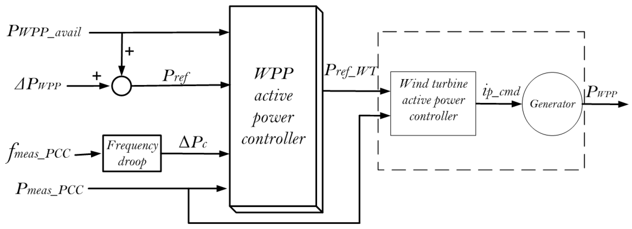
To assess the performance of the wind power plant on the power system level in controlling the active power during large-scale wind power penetration, it is important to assess the performance of WPP compared to the performance of individual turbines. This study developed a simplified aggregated WPP model based on the IEC 61400-27-1 recommendations [30]. The developed generic WPP model as shown in Figure 4 has been further simplified for the purpose of primary and secondary active power control.
The aggregated WPP model had a hierarchical control level, i.e., active power was controlled at the WPP level and at the wind turbine level. The WPP control level provided reference power to the wind turbine controller ( P r e f _ W T ) based on the reference power signal ( P r e f ), the measured power at PCC ( P m e a s _ P C C ) and the required primary response ( Δ P c ). The Prefwas decided based on the available wind power ( P W P P _ a v a i l ) and the required response from AGC ( Δ P W P P ). The WPP controller and the wind turbine controller were comprised of PI controllers. The PI controller at the WPP level minimized the error between P m e a s _ P C C and the required response, i.e., the sum of P r e f and Δ P c . The WT controller and the static generator simulated the relevant dynamic response of the WPP based on the signals P r e f _ W T and P m e a s _ P C C .

2.3. Regulating Power Plan

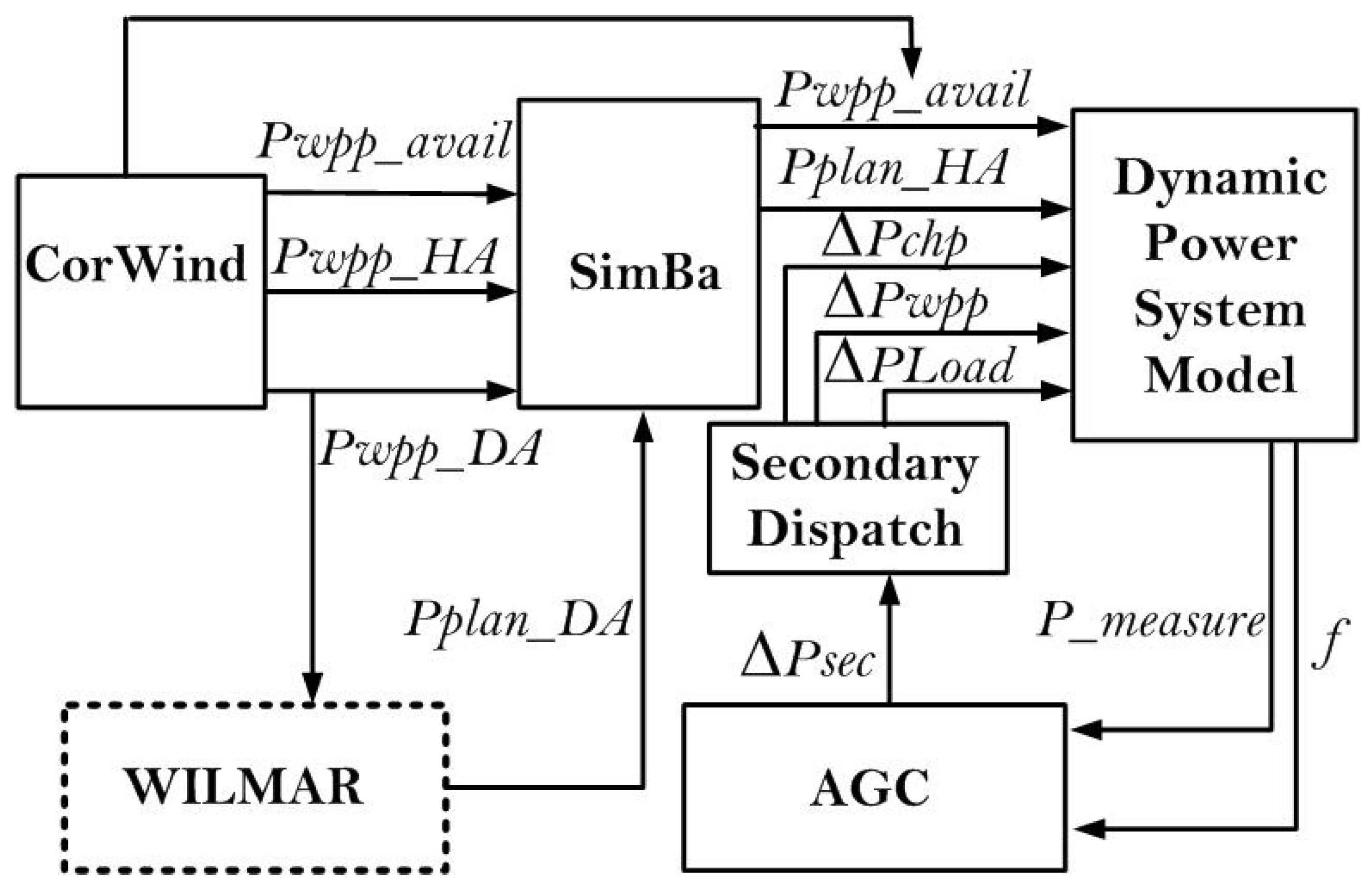
As previously mentions, the regulating power plan for the generating units, loads and interconnections was provided by the power balance model, SimBa [27]. The hour-ahead forecast of wind power and the day-ahead market model provided the base data for the generation of the power plan. HA forecast of wind power was provided by Correlated Wind (CorWind), and day-ahead plan data were provided by Wind power Integration in Liberalized electricity Markets (WILMAR) [27]. The regulating power plan arrangement based on data from WILMAR, CorWind, SimBa and AGC is shown in Figure 5.
Grid codes and the dynamics were taken into account by SimBa, while providing the the regulating power plan. WILMAR and CorWind provide input to SimBa. WILMAR provides energy production, import, export and load demand in one hour resolution, while CorWind provides the forecasting data for wind and wind power generation data in real time. SimBa takes the input data, balances the input from WILMAR and CorWind and generates a real power regulation plan for power plants and interconnections with five-minute resolution, i.e., P p l a n H A . SimBa compiles a list of regulating bids based on production capacity, bidding price and the marginal cost function of each unit and generates an hour-ahead five minute-resolution plan ( P P l a n H A ), for each power plant and the power exchange with the neighboring power systems. SimBa takes power exchange and ramp limitations for generating units. Power exchange ramps for Nordic and CEpower systems are 30 and 10 min, respectively. Power exchange between the CE power system starts 5 min before the agreed hour, while for the Nordic power system, it starts 15 min before the agreed hour [31].
A mismatch between generation and load occurs when the wind speed differs from the forecasted value due to inevitable forecasting error. To maintain the power balance in such situations, primary response is provided by the speed governors and then by AGC. Due to forecasting errors, real-time wind generation is usually not equal to HA wind forecast, thus creating a real power imbalance, which will be mitigated by activating reserve power through speed governors and AGC.

2.4. Automatic Generation Control

Figure 6 represents the model of AGC implemented in this study. The AGC monitored the changes in frequency ( Δ f ) and the power exchange with the interconnections. As the frequency deviated from its nominal value or the scheduled power exchange, given by Equation (9), it generated an error known as Area Control Error (ACE). P A C E is the total imbalance power in the control area under study. It is the sum of Δ P , which is the primary response from interconnection, and the product of Δ f and biasing factor B. B is the droop characteristic of all generating units that provide the primary response for frequency stability [25]. PI controllers were used to minimize the P A C E to zero by calculating the required power set points for the power plants.
Δ P e x c h a n g e = P e x c h a n g e _ S c h e d u l e P e x c h a n g e
P A C E = Δ P + ( Δ f · B )
Proportional integral controllers were used in AGC to minimize P A C E , as given in Equation (11):
Δ P s e c = K · Δ P A C E + K T Δ P A C E d t
The values of parameters K and T were required to return the system to its nominal frequency and exchange power with the set point. In interconnected systems, the value of these parameters was determined by common guidelines for a coordinated secondary control. As mentioned in [32], in the CE power system, the proportional constant (K) ranges from 0–0.5, while the value of the time constant (T) ranges from 50–200s. The time constant (T) is the measure of the tracking speed of secondary controllers that control the activation of power from participating generators. The required change in production Δ P s e c is then distributed among actively-participating generators and flexible loads, as shown in Figure 6. The dispatch block took Δ P , WPPs power generation ( Δ P W P P ), CHPs power generation ( P C H P ) and the available wind power ( P W P P _ a v a i l ) as input and determined the required change in the reference power for the participating generation units, i.e., Δ P C H P and Δ P W P P and change in load.

3. Performance Analysis through Case Studies

The power system model developed for this study included aggregated models for WPP, CHP and DCHP, system interconnections, load and the AGC system. The dynamics on AC interconnection were studied through external grid, which emulated the specific characteristics of the Nordic grid having an inertia of 16 s and a primary frequency response of 600 MW/0.1 Hz. Table 1 provides the capacities of the generating units, system load and system interconnection.
Conventionally, secondary reserves are activated manually or through AGC, where static optimization techniques is used. The static optimization technique defines the participation factor and re-dispatches the power plants without considering the operating constraints of generating units and its real-time loading. The increasingly large-scale integration of renewables requires a dispatch strategy that not only takes into account the cost of reserve power, but also its availability from generating units and the dispatch limits. This study has developed an optimized real-time dispatch strategy for AGC that will be advantageous for modern power systems coping with the intermittent nature of renewables when a large scale of renewable power is integrated.
Case studies have been simulated for analyzing the coordinating dispatch strategy for AGC. In the first case study, load generation balance was controlled with WPPs and CHPs, while WPPs and cold storage units mitigated the imbalances in the second case study. The study utilized data for a particular day for the year 2020, when conventional generating units are scheduled to generate 14.12 GWh when available wind power is 46.59 GWH with a load demand of 30.84 GWh. The availability of wind allowed WPP to generate 76.7% of the total generation with net power export of 29.38 GWH to neighboring power systems [15]. To cope with the imbalances on high windy days, the primary response was provided by conventional and WPPs, while the secondary response was provided through AGC, where 90 MW was kept as reserved power.

3.1. Case Study 1: Power Balance Control through WPPs and CHPs

Transmission System Operators (TSOs) provide economic dispatch to the power plants while utilizing available wind power as much as possible, due to their lower incremental cost. However, the frequency stability of the power systems with high wind penetrations requires active response from WPP to maintain real-time power balance. The wind power in real time may differ from the forecasted values of the hour-ahead power plan generated by SimBa, resulting in power imbalances. The generating units sense the imbalance as speed change in their rotor speed and respond by activating primary reserves. The activation of primary reserves depends on the characteristics of power plants and the power system.
Large-scale wind power integration requires an active participation from WPPs along with conventional power plants. WPPs are able to respond to positive and negative power imbalances only if the delta production constraint function is activated. According to Danish grid codes presented in [33], Grid connection of wind turbine to network with voltages above 100 kV, Regulation TF 3.2.5, the delta production constraint function limits the current power production of a WPP by a fixed amount, thereby setting aside reserve for handling critical power requirements. However, WPP operating in the delta operating constraint adds to the operating cost as limited power from WPP has to be generated from conventional generating units. Therefore, this case study discussed a methodology where WPP while generating available power shall respond to power balances due to the generation excess (negative power imbalances), while CHPs shall respond to both positive and negative power imbalances, as shown in Figure 7.
where:
  • C P W P P = WPP generation cost
  • C P C H P = CHP generation cost
  • Δ P W P P = Secondary dispatch from WPP
  • Δ P C H P = Secondary dispatch from CHP
  • P W P P _ m i n = Minimum generational level of WPP
  • P W P P _ a v a i l = Maximum generational level of WPP
  • P C H P _ m i n = Minimum generation of CHP
  • P C H P _ m a x = Maximum generation of CHP
  • Δ P C H P _ U p L i m = Upper dispatch limit of CHP
  • Δ P C H P _ L o w L i m = Lower dispatch limit of CHP
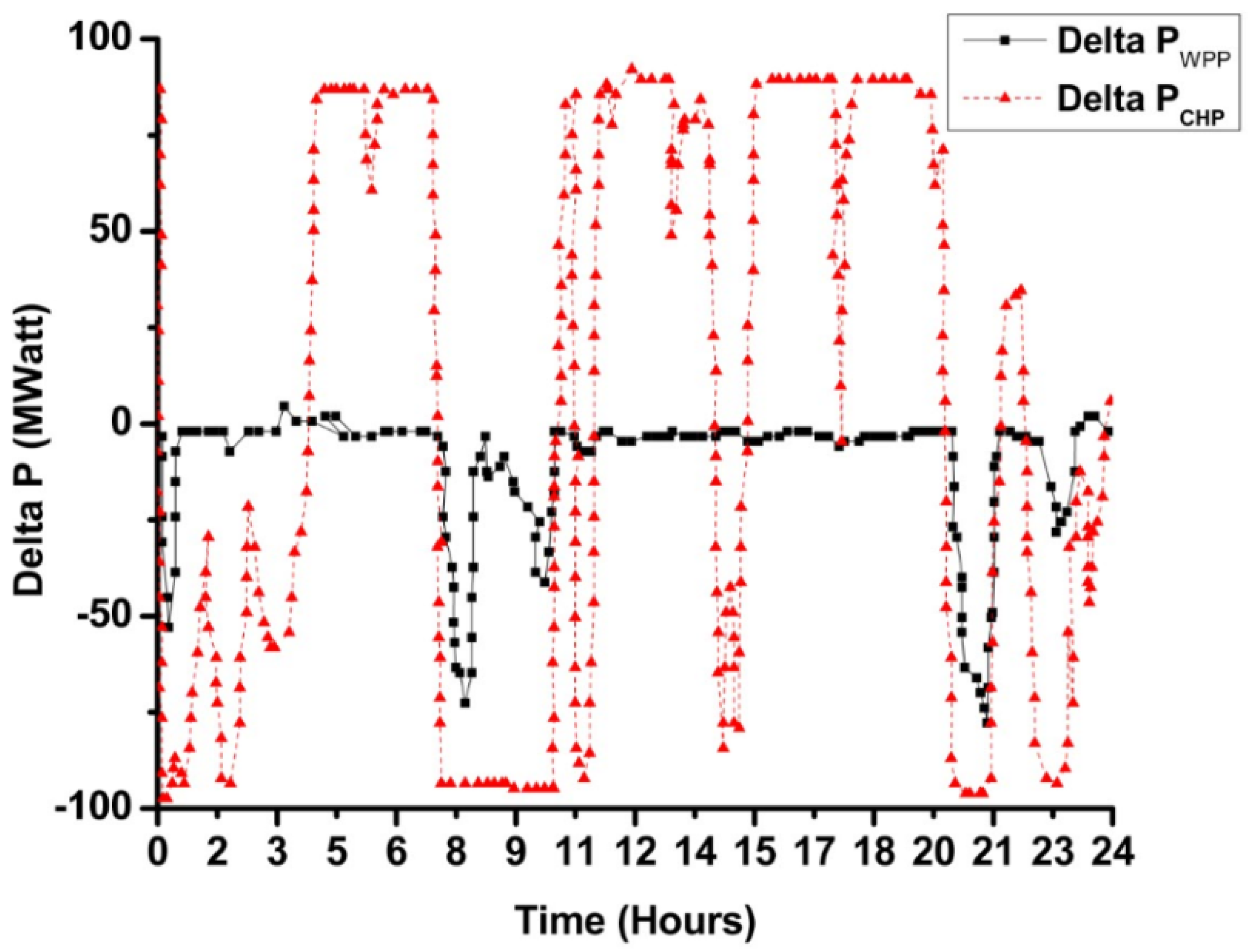
In a power system with high wind power penetration, the dispatch strategy as shown in Figure 7 is useful as the conventional power plants can operate at their lower limits, while WPP utilizes the maximum power available in the wind. The generation from WPP is curtailed only during generation excess, i.e., Δ P s e c < 0 , while CHP can activate reserves (±90 MW) during generation excess or deficiency. WPP will curtail the generation only when the CHP is not able to provide the response, i.e., CHPs are either operating at their lower limits ( P C H P _ m i n ) or secondary dispatch from AGC Δ P s e c reaches Δ P C H P _ L o w L i m . However, when up-regulation is required, i.e., Δ P s e c > 0 , a command is generated by the AGC wind power plants that are unable to respond, as they are already operating at their Maximum Power Point (MPP). In this scenario, only CHP will respond by activating the reserved power. The real-time secondary dispatch from WPP and CHP, as shown in Figure 8, minimizes the deviations in frequency and scheduled power exchange with interconnections. WPP and CHP contribute to power minimum imbalances while keeping the generation cost at its minimum. WPP down-regulates only when CHP is operating at its lower limit, usually set to 20% of its capacity, or secondary reserves from CHP reach its minimum level, i.e., −90 MW. As it is unable to further contribute to real power regulation, thus the WPP dispatch will regulate by curtailing energy production according to the requirement of the system.
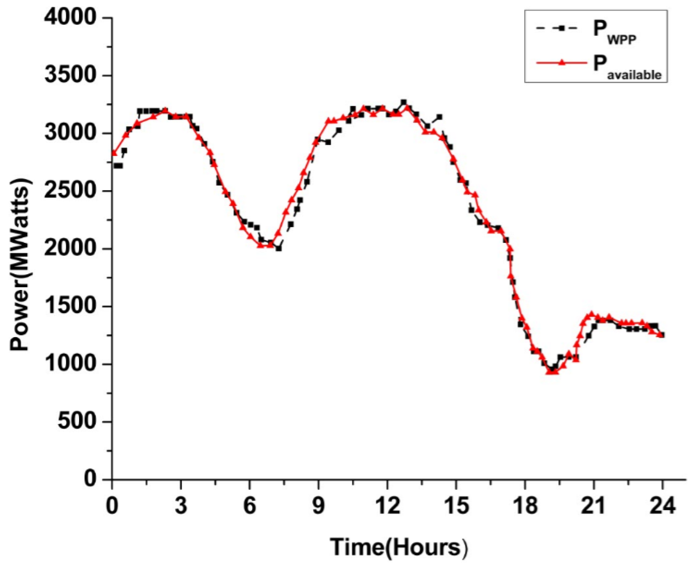
Figure 9 shows the available and generated wind power data for a certain day. A difference between available and generated power ( P W P P ) can be noticed, which is due the contribution of WPP in active power balance. This contribution is a profitable and realizable solution, as without integration of WPP in AGC, TSOs will not be able to operate at the minimum, and regulation of these imbalances by CHP will result in increased operational cost.
Moreover, this research work also compared the aforementioned case with cases when WPP was not contributing to system ancillary services. The results were taken from the previous study carried out by [3]. The active power balance was achieved by CHP only, and WPP was always operating at the maximum. This comparison is shown in Figure 10.
Figure 10 provides a comparison between power imbalances with and without integration of WPP in AGC. These power imbalances were also compared with initial power imbalances. Traditionally, the reserve power is only kept on conventional generating units as the case of AGC-controlled CHP presented in Figure 10. However, the limitations on reserve power and slower generating unit response result only in higher imbalance than the case where WPPs provide the active support along with conventional power plant. The active participation of wind power plants in AGC makes the operation of the power system more secure and allows the CHP to operate at their lower limits, thereby reducing the overall system operation cost. The wind power can also be kept as reserve power for situations where the generation is deficient, but this will only result in increasing the operational cost, as the power kept as reserve from WPP will be generated by conventional power plants or imported from neighboring power systems if not utilized in the secondary dispatch process. Rather than keeping reserve wind power, it is more economical to keep WPP production at its maximum due to the lower incremental cost and to down-regulate only when necessary.
This study shows the WPP contribution to real-time power balance, and its integration in AGC can decrease the operational costs of the system with bulk wind power integrated power systems. The idea of integrating WPP is of significance when WPP can contribute highly to the total electricity production. This allows less generation from conventional power plants, thereby minimizing the CO 2 emissions and reducing the overall operation cost.

3.2. Case Study 2: Power Balance Control through WPPs and Flexible Loads

This section details the power balance control though WPPs and flexible load. Simulation parameters for load, generation and power exchange were kept the same as those used for Case 1. Primary regulation was provided by the conventional generators, whereas WPP and flexible loads were used for secondary response. As mentioned in Section 2.1, this study assumed that the flexible consumption unit can provide regulation of 90 MW through AGC without compromising its primary purpose. The secondary dispatch from AGC is shown in Figure 11.
where
  • C P W P P = Cost of power generation from WPP
  • C P C H P = Cost of power generation from CHP
  • Δ E s e c = Energy activated through secondary response
  • Δ E T h r e s h o l d = Energy extracted through flexible units
  • Δ P W P P = Secondary dispatch from WPP
  • Δ P C H P = Secondary dispatch from CHP
Subsequent to the activation of primary reserves, the AGC response through WPP and flexible load unit minimized the power imbalance and released primary reserves. The required secondary response Δ P s e c was divided between flexible loads and WPPs, as shown in Figure 11. When the frequency deviated and P A C E was generated, the secondary reserves were activated by the AGC to minimize P A C E , as shown in Figure 12. Figure 13 shows the situation when WPP was regulated for positive frequency deviations and flexible load consumption was regulated when the frequency deviation was negative.
The secondary response by WPP and flexible loads maintained the real power balance and frequency at the nominal level. Frequency and power exchange deviations are shown in Figure 13 after the activation of secondary reserves. A comparison can also be drawn from these figures between Case 1 where secondary regulation was provided by WPP and CHP and Case 2 where secondary regulation was provided by WPP and flexible loads. It can be seen from Figure 13 that the response was similar for both cases, but overshoots caused by the slow response of CHP were minimized when the response was provided by WPP and load consumption. Figure 14 shows this power exchange deviation with interconnections at 18.00 h.
The response by CHP was slower depending on ramp rate constraints limited by the boiler, while flexible loads responded quickly to frequency deviations, but the response here, as shown in Figure 13 and Figure 14, were similar in both cases due to the slow AGC response. To quantify reserve activation from WPP and flexible load units, the AGC activated 1.4 GWh of energy from WPP during generation excess and during generation deficit and 0.699 GWh from flexible load units without impacting its primary responsibility. If WPP and loads are not utilized, then a large amount of reserves will be required from conventional power plants to cope with active power imbalances in a power system with large wind power integration. This will not only reduce the operational cost, but CO 2 emissions, as well.

4. Conclusions

This paper investigated the problem of power balancing in a modern power system with large-scale integration of wind power. A coordinated control strategy between flexible loads, WPP and conventional power plants was presented to mitigate power imbalances that occur due to the wrong forecast of wind power. Simulations for a scenario forecasted for the modern Danish power system when WPPs were generating 76.7% of the total electricity generation verified the proposed strategy. The study illustrated that power imbalances created due to the wrong forecast of wind power were compensated by utilizing 1.4 GWh of energy from WPP and 0.699 GWh from cold storage units, thereby minimizing the need for extra reserve power from conventional power plants.

Author Contributions

This study was conducted as part of a Ph.D. project funded by the Sino-Danish Center for Education and Research (SDC) at Denmark technical university by A.B. under the supervision of A.D.H., A.B. conceptualized, wrote the paper and completed the simulation for the case studies as the first author. T.A. and K.U. curated and analyzed the data. G.M. and A.Y.A. verified the methodology and results. All authors discussed the simulation results and approved the publication.

Funding

This research project is funded by USAID Pakistan and the Sino-Danish Center for Education and Research (SDC).

Conflicts of Interest

The authors declare no conflict of interest. The funders had no role in the design of the study; in the collection, analyses, or interpretation of data; in the writing of the manuscript; nor in the decision to publish the results.

Abbreviations

The following abbreviations are used in this manuscript:
AGCAutomatic Generation Control
WPPsWind Power Plants
CPLCold Storage Power Plants
EVElectric Vehicles
HPHeat Pumps
CHPCentralized Combined Heat and Power plant
DCHPDe-centralized Combined Heat and Power plant
HAHour-Ahead
TSOTransmission System Operator

References

  1. Basit, A.; Hansen, A.D.; Sørensen, P.E.; Giannopoulos, G. Real-time impact of power balancing on power system operation with large scale integration of wind power. J. Mod. Power Syst. Clean Energy 2017, 5, 202–210. [Google Scholar] [CrossRef]
  2. Aziz, A.; Shafiullah, G.; Stojcevski, A.; Mto, A. Participation of DFIG based wind energy system in load frequency control of interconnected multigeneration power system. In Proceedings of the IEEE 2014 Australasian Universities Power Engineering Conference (AUPEC), Perth, Australia, 28 September–1 October 2014; pp. 1–6. [Google Scholar]
  3. Basit, A.; Hansen, A.D.; Altin, M.; Sørensen, P.E.; Gamst, M. Compensating active power imbalances in power system with large-scale wind power penetration. J. Mod. Power Syst. Clean Energy 2016, 4, 229–237. [Google Scholar] [CrossRef]
  4. Basit, A.; Hansen, A.D.; Altin, M.; Sørensen, P.E.; Gamst, M. Wind power integration into the automatic generation control of power systems with large-scale wind power. J. Eng. 2014, 2014, 538–545. [Google Scholar] [CrossRef] [Green Version]
  5. Basit, A.; Hansen, A.D.; Altin, M.; Sørensen, P. Analysis of Highly Wind Power Integrated Power System model performance during Critical Weather conditions. In Proceedings of the Wind Integration Workshop (WIW14), Berlin, Germany, 11–13 November 2014. [Google Scholar]
  6. Nikoobakht, A.; Aghaei, J. IGDT-based robust optimal utilisation of wind power generation using coordinated flexibility resources. IET Renew. Power Gener. 2016, 11, 264–277. [Google Scholar] [CrossRef]
  7. García-González, J.; Contreras, A.; Formozo, C.; Vallés, M.; Rivero, E.; Lobato, E.; Ramos, A.; Frías, P.; Egido, I.; Sánchez, P.; et al. Economic Impact Analysis of the Demonstrations in Task-Forces TF1 and TF3-Deliverable D15. 1: WP15. Economic Impacts of the Demonstrations, Barriers towards Scaling Up and Solutions; DTU Lyngby: Lyngby, Denmark, 2014. [Google Scholar]
  8. Aziz, A.; Oo, A.T.; Stojcevski, A. Analysis of frequency sensitive wind plant penetration effect on load frequency control of hybrid power system. Int. J. Electr. Power Energy Syst. 2018, 99, 603–617. [Google Scholar] [CrossRef]
  9. Lu, L.; Tu, J.; Chau, C.K.; Chen, M.; Lin, X. Online Energy Generation Scheduling for Microgrids with Intermittent Energy Sources and Co-Generation; ACM: New York, NY, USA, 2013; Volume 41. [Google Scholar]
  10. Narayanaswamy, B.; Garg, V.K.; Jayram, T. Online optimization for the smart (micro) grid. In Proceedings of the 3rd International Conference on Future Energy Systems: Where Energy, Computing and Communication Meet, Madrid, Spain, 9–11 May 2012; p. 19. [Google Scholar]
  11. Chang, T.H.; Alizadeh, M.; Scaglione, A. Real-time power balancing via decentralized coordinated home energy scheduling. IEEE Trans. Smart Grid 2013, 4, 1490–1504. [Google Scholar] [CrossRef]
  12. Sun, S.; Dong, M.; Liang, B. Real-time welfare-maximizing regulation allocation in dynamic aggregator-EVs system. IEEE Trans. Smart Grid 2014, 5, 1397–1409. [Google Scholar] [CrossRef]
  13. Sun, S.; Dong, M.; Liang, B. Real-time power balancing in electric grids with distributed storage. IEEE J. Sel. Top. Signal Process. 2014, 8, 1167–1181. [Google Scholar] [CrossRef]
  14. Huang, Y.; Mao, S.; Nelms, R.M. Adaptive electricity scheduling in microgrids. IEEE Trans. Smart Grid 2014, 5, 270–281. [Google Scholar] [CrossRef]
  15. Xiang, L.; Ng, D.W.K.; Lee, W.; Schober, R. Optimal storage-aided wind generation integration considering ramping requirements. In Proceedings of the 2013 IEEE International Conference on Smart Grid Communications (SmartGridComm), Vancouver, BC, Canada, 21–24 October 2013; pp. 648–653. [Google Scholar]
  16. Huang, L.; Walrand, J.; Ramchandran, K. Optimal power procurement and demand response with quality-of-usage guarantees. In Proceedings of the 2012 IEEE Power and Energy Society General Meeting, San Diego, CA, USA, 22–26 July 2012; pp. 1–8. [Google Scholar]
  17. Chen, S.; Shroff, N.B.; Sinha, P. Heterogeneous delay tolerant task scheduling and energy management in the smart grid with renewable energy. IEEE J. Sel. Areas Commun. 2013, 31, 1258–1267. [Google Scholar] [CrossRef]
  18. Guo, Y.; Pan, M.; Fang, Y.; Khargonekar, P.P. Decentralized coordination of energy utilization for residential households in the smart grid. IEEE Trans. Smart Grid 2013, 4, 1341–1350. [Google Scholar] [CrossRef]
  19. Sun, S.; Dong, M.; Liang, B. Distributed real-time power balancing in renewable-integrated power grids with storage and flexible loads. IEEE Trans. Smart Grid 2016, 7, 2337–2349. [Google Scholar] [CrossRef]
  20. Zhang, Y.; Gatsis, N.; Giannakis, G.B. Robust energy management for microgrids with high-penetration renewables. IEEE Trans. Sustain. Energy 2013, 4, 944–953. [Google Scholar] [CrossRef]
  21. Salinas, S.; Li, M.; Li, P.; Fu, Y. Dynamic energy management for the smart grid with distributed energy resources. IEEE Trans. Smart Grid 2013, 4, 2139–2151. [Google Scholar] [CrossRef]
  22. Uslu, U.; Zhang, B.; Pillai, J.R.; Chaudhary, S.K.; Bak-Jensen, B.; de Cerio Mendaza, I.D. Participation of flexible loads in load frequency control to support high wind penetration. In Proceedings of the 2016 IEEE Innovative Smart Grid Technologies-Asia (ISGT-Asia), Melbourne, Australia, 28 November–1 December 2016; pp. 442–447. [Google Scholar]
  23. Pillai, J.R.; Bak-Jensen, B. Integration of vehicle-to-grid in the western Danish power system. IEEE Trans. Sustain. Energy 2011, 2, 12–19. [Google Scholar] [CrossRef]
  24. Basit, A.; Hansen, A.D.; Sørensen, P. Dynamic model of frequency control in Danish power system with large scale integration of wind power. In Proceedings of the 2013 China Wind Power Conference (CPW’13), Beijing, China, 16–18 October 2013; pp. 16–18. [Google Scholar]
  25. Hovgaard, T.G.; Larsen, L.F.; Skovrup, M.J.; Jørgensen, J.B. Power consumption in refrigeration systems-modeling for optimization. In Proceedings of the 2011 International Symposium on Advanced Control of Industrial Processes (ADCONIP), Hangzhou, China, 23–27 May 2011; pp. 234–239. [Google Scholar]
  26. Basit, A.; Hansen, A.; Altin, M.; Sørensen, P. Balancing modern Power System with large scale of wind power. In Proceedings of the China Wind Power (CWP2014), Beijing, China, 22–24 October 2014. [Google Scholar]
  27. Basit, A.; Altin, M. Wind Power Plant System Services. Ph.D. Thesis, DTU Wind Energy, Roskilde, Denmark, 2014. [Google Scholar]
  28. Report, I.C. Dynamic models for steam and hydro turbines in power system studies. IEEE Trans. Power Appar. Syst. 1973, PAS-92, 1904–1915. [Google Scholar] [CrossRef]
  29. CIGRE. Modeling of Gas Turbines and Steam Turbines in Combined Cycle Power Plants; CIGRE Technical Brochure 238; CIGRE: Paris, France, April 2003. [Google Scholar]
  30. Draft, I.C. Electrical Simulation Models for Wind Power Generation Wind Turbines; IEC Std. Committee Draft (CD) 88/424/CD; IEC: Geneva, Switzerland, 2012. [Google Scholar]
  31. ENTSOE. Continental Europe Operation Handbook P1 Load-Frequency Control and Performance; ENSTO-E: Brussels, Belgium, 2003. [Google Scholar]
  32. Rebours, Y.G.; Kirschen, D.S.; Trotignon, M.; Rossignol, S. A survey of frequency and voltage control ancillary services Technical features. IEEE Trans. Power Syst. 2007, 22, 350–357. [Google Scholar] [CrossRef]
  33. Singh, B.; Singh, S. Wind power interconnection into the power system: A review of grid code requirements. Electr. J. 2009, 22, 54–63. [Google Scholar] [CrossRef]
Figure 1. Power system model.
Energies 12 01710 g001
Figure 2. Aggregated CHP model.
Energies 12 01710 g002
Figure 3. Aggregated DCHP model.
Energies 12 01710 g003
Figure 4. Aggregated WPP model.
Energies 12 01710 g004
Figure 5. Regulating power plan arrangement based on data from Wind power Integration in Liberalized electricity Markets (WILMAR), Correlated Wind (CorWind), SimBa and AGC.
Energies 12 01710 g005
Figure 6. Automatic Generation Control (AGC).
Energies 12 01710 g006
Figure 7. Secondary dispatch strategy for WPPs and CHPs.
Energies 12 01710 g007
Figure 8. Secondary dispatch from CHP and WPP.
Energies 12 01710 g008
Figure 9. Available and generated wind power.
Energies 12 01710 g009
Figure 10. Comparison of power imbalances.
Energies 12 01710 g010
Figure 11. Secondary dispatch strategy for WPPs, CHPs and flexible loads.
Energies 12 01710 g011
Figure 12. Secondary response from AGC.
Energies 12 01710 g012
Figure 13. Power system frequency and deviation in power exchange with interconnections.
Energies 12 01710 g013
Figure 14. Zoom view of power exchange deviation.
Energies 12 01710 g014
Table 1. Capacities of generating units and system interconnections.
Power System ModelGenerating UnitsSystem Interconnections
CHP
(MW)
DCHP
(MW)
WPP
(MW)
Sweden
(MW)
Great Belt Link
(MW)
Germany
(MW)
Capacities175422028001700600600