Design and Simulation of a 1 DOF Planetary Speed Increaser for Counter-Rotating Wind Turbines with Counter-Rotating Electric Generators


Abstract
:1. Introduction
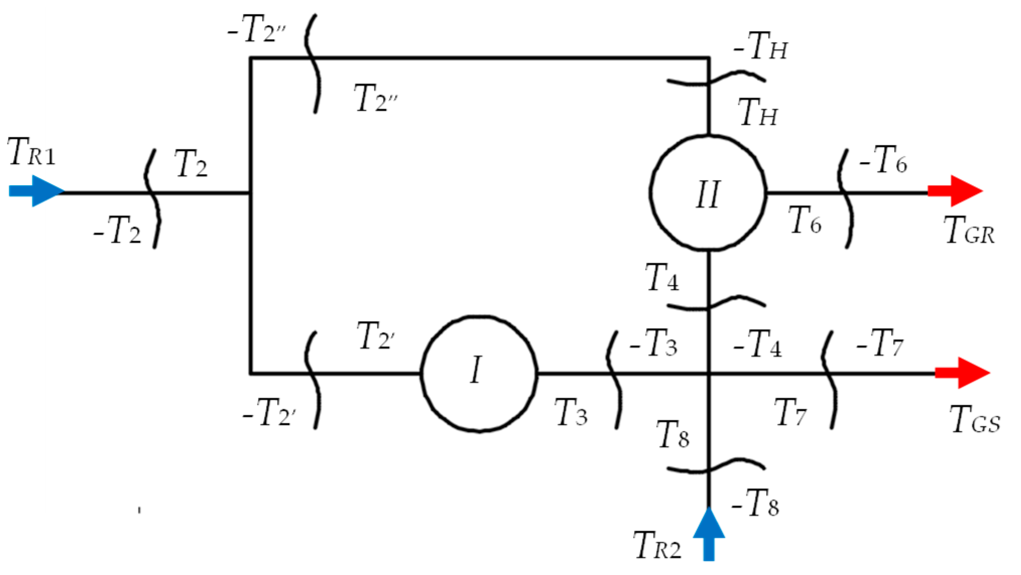
2. Problem Formulation
- The correlations for the input shafts:
- The correlations for the output shafts:
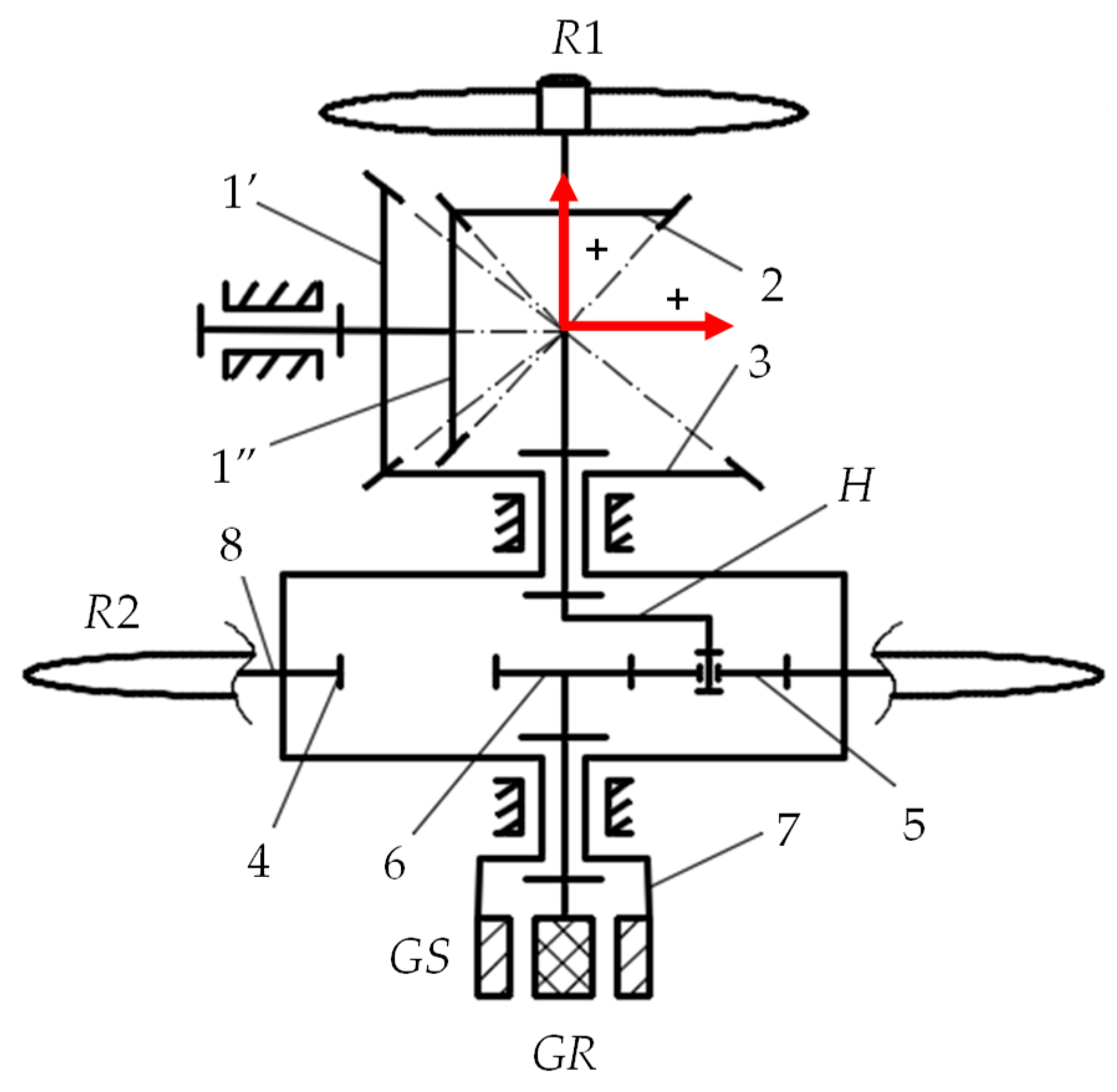
- The correlations for the bevel mechanism with fixed axes I:for , and , while is the interior efficiency of transmission I, and are the efficiencies of the two component bevel gear pairs, zi—the teeth number of the component gears, i = 1’, 1″, 2, 3.
- The correlations for the connections between the planetary gear set II and the bevel transmission I:
- The correlations for the external links:where represents the speed of the equivalent electric generator.
3. Kinematic Modeling
4. Modeling of Torques and Efficiency
5. Numerical Simulations and Interpretation
- (a)
- The correlative influence of the amplification kinematic ratio iaR1_eg and the kt ratio on the speed increaser efficiency; in this regard, a unitary input power at the main wind rotor is used, e.g., PR1 = 1 kW ( ).
- (b)
- The power flow distinct cases depending on the kt ratio values, for a particular value of the kinematic ratio, i.e., iaR1_eg = 18: four functional cases are identified, and detailed in the subchapter 5.2 under the assumptions of considering and neglecting the friction in the gear pairs.
- (c)
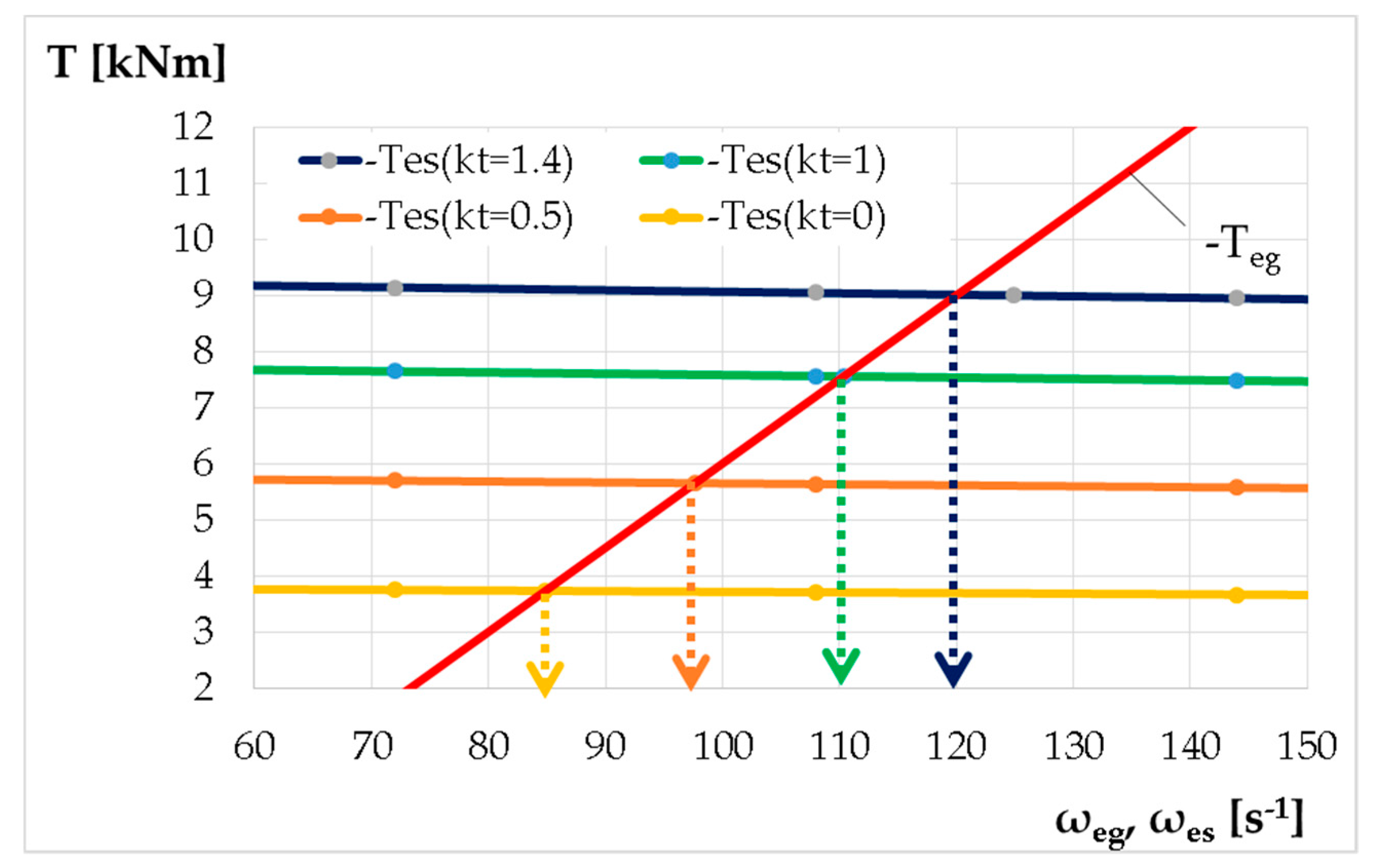
- The operating point of the wind system for the previous four functional cases.
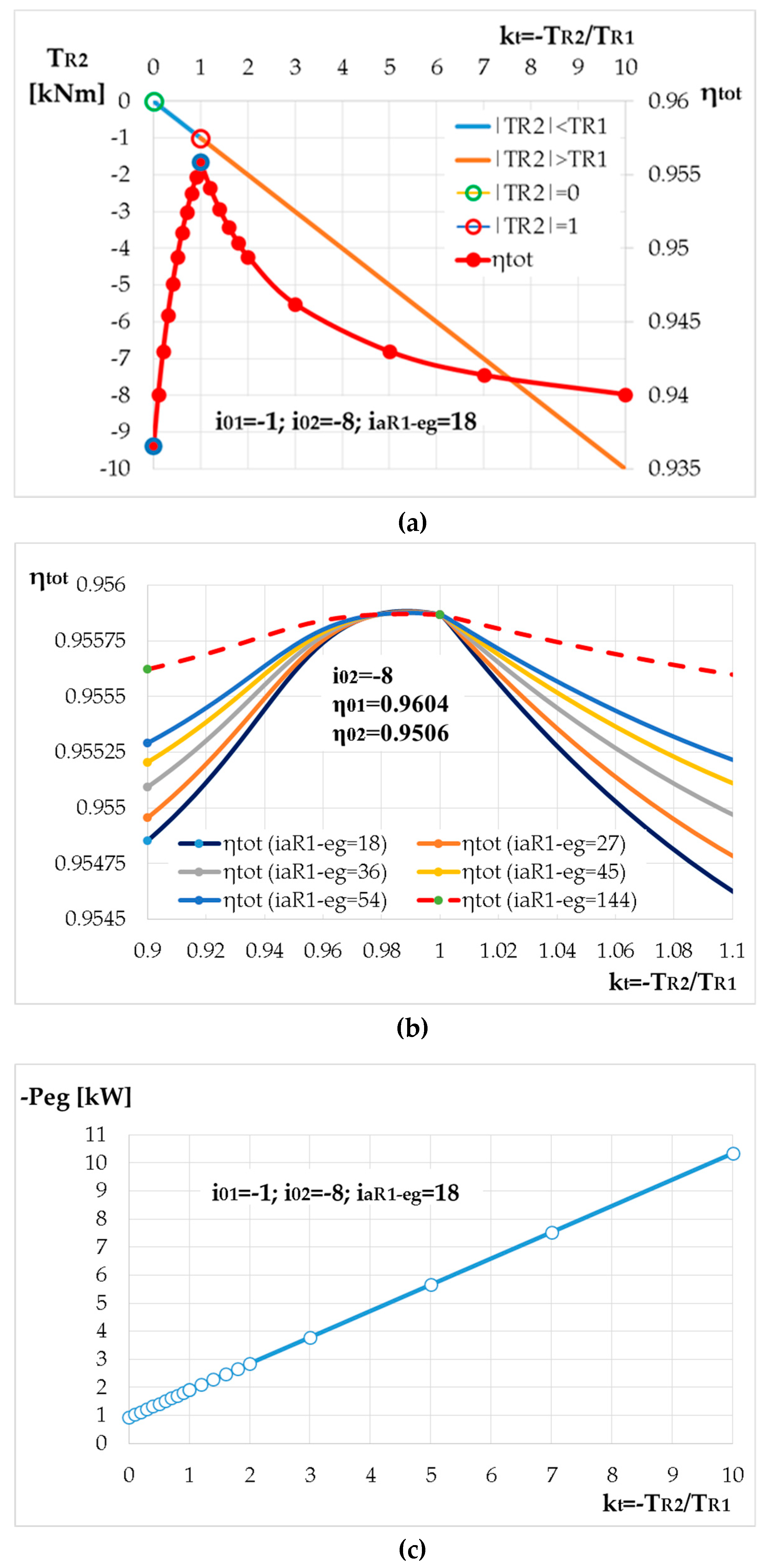
5.1. The Influence of the Amplification Kinematic Ratio and the Input Torques Ratio
- -
- the efficiency does not depend on the ratio in the case kt = 1, i.e., the input torques TR1 and TR2 are equal in absolute value, the efficiency being at its maximum value , Figure 4a,b;
- -
- for lower values of the kt parameter (kt < 0.1), the efficiency decreases continuously with the increase of the amplification kinematic ratio, Figure 4b; the efficiency has a growing trend for higher subunit values (0.1 < kt < 1) and in the range of high values of the amplification ratio, Figure 4b;
- -
- if the secondary wind rotor generates higher torques than the main rotor, |TR2| > TR1 (i.e., kt > 1), the efficiency increases continuously with the increase of the amplification kinematic ratio (Figure 4b, kt = 1.2).
- -
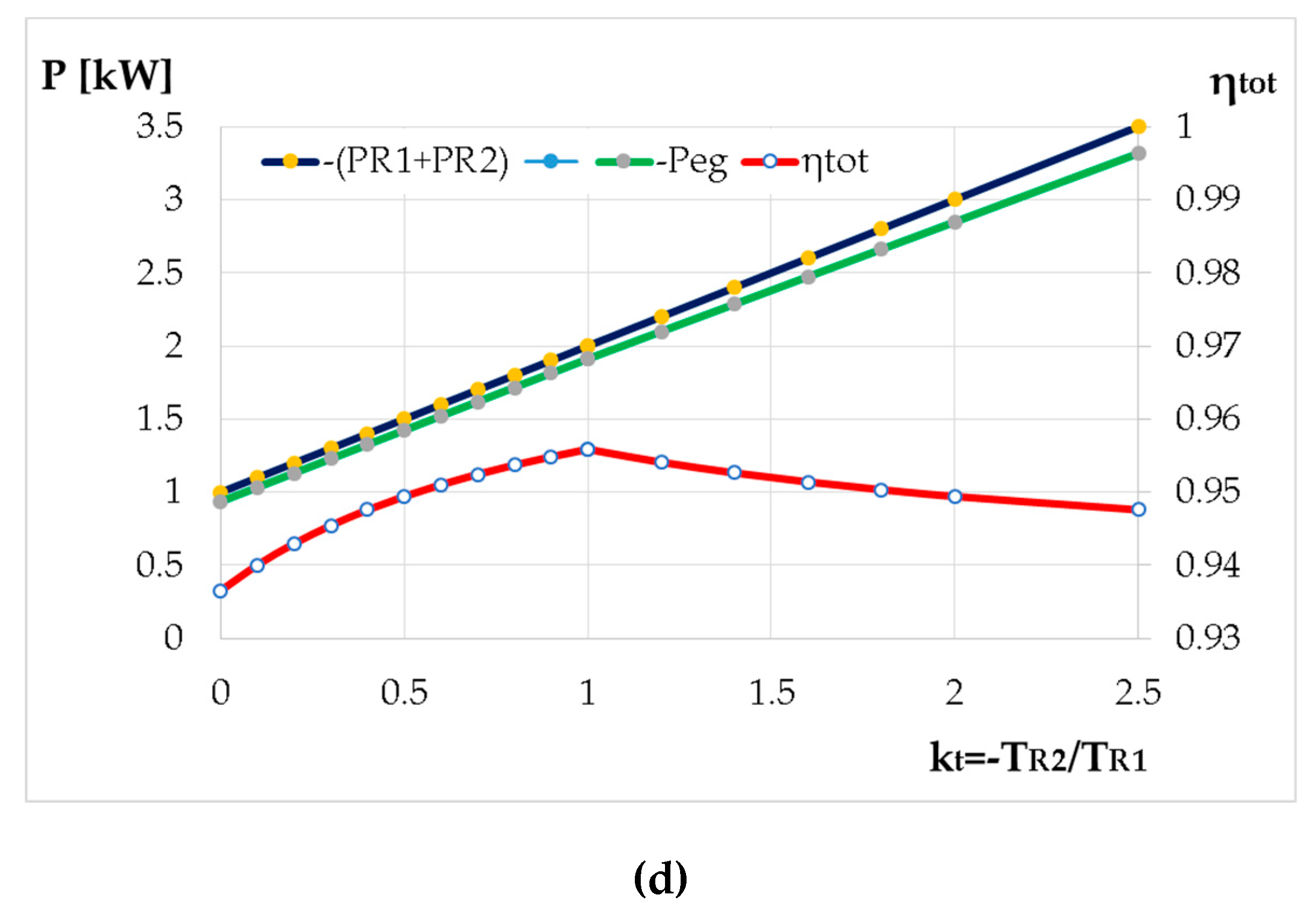
- the transmission efficiency increases with the increase of the kt ratio until the secondary wind rotor torque becomes equal to that of the main rotor (kt = 1), after which it decreases continuously with the increase of kt ratio, regardless of the value of the amplification ratio (Figure 5a,b);
- -
- the useful mechanical power Peg at the equivalent generator input has a linear variation with respect to kt (Figure 5c,d), being directly dependent on the power introduced in the system by the secondary wind rotor R2.
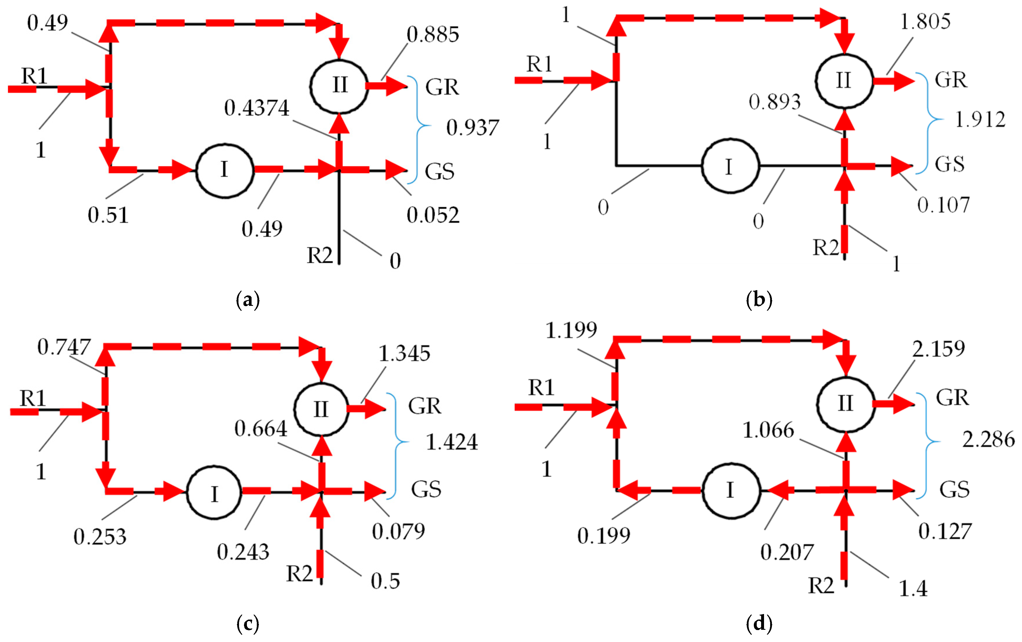
5.2. Power Flow
- Case 1: the torque of the secondary wind rotor is null , i.e., , Figure 6a and Figure 7a. This situation occurs when the secondary wind turbine is set so as not to generate mechanical power, the gearbox thus running with one input and two outputs at the efficiency value , in case of considering friction (Figure 7a);
- Case 2: , Figure 6b and Figure 7b. In this situation, the bevel transmission I is no longer involved in the mechanical power transmitting and, thus, decoupling of the two power inputs occurs: the power generated by the main wind rotor R1 is entirely transmitted to the generator rotor GR, the secondary wind rotor R2 ensures the power requirements for the generator stator GS, and the power difference is transmitted to the GR rotor. In this case, the gearbox efficiency becomes , Figure 7b.
- Case 3: , Figure 6c and Figure 7c. The power of the main wind rotor R1 branches through the two transmissions I and II, the flow through the bevel mechanism I merges with the power flow of the wind rotor R2, which is then distributed to the generator stator GS and to the generator rotor GR. In this case, for a power of the R2 rotor equal to 0.5 of the R1 rotor power; according to Figure 7c, a gearbox efficiency of is obtained.
- Case 4: , Figure 6d and Figure 7d. In this case, the power generated by the secondary wind rotor R2 is transmitted in a branched way to the stator GS and to the rotor GR by both transmissions I and II. As a result, the power flow through the transmission I is reversed with respect to case 3, a part of the power generated by the secondary wind rotor R2 being summed up with that of the main rotor R1 and then transmitted to the generator rotor GR through the planetary gear set II. For the numerical example, the planetary transmission efficiency is , Figure 7d.
5.3. Operating Point
6. Conclusions
Author Contributions
Funding
Conflicts of Interest
Nomenclature
| WT | Wind turbine | DOF | Degree of freedom |
| CRWT | Counter-rotating wind turbine | M | Mechanism degree of freedom |
| CRWR | Counter-rotating wind rotors | GR | Electric generator rotor |
| CREG | Counter-rotating electric generator | GS | Electric generator stator |
| R1 | Main wind rotor | L | Number of mechanism inputs and outputs |
| R2 | Secondary wind rotor | eg | Equivalent electric generator |
| SI | Speed Increaser | ia | Amplification kinematic ratio |
| ω | Angular speed | η0 | Transmission interior efficiency |
| T | Torque | i0 | Transmission interior kinematic ratio |
| kt | Input torques ratio | ηtot | Efficiency of the speed increaser |
| z | Gear teeth number | es | Equivalent output shaft of the transmission |
| H | Planetary carrier | PR1,2 | Power of the wind rotor R1,2 |
References
- Booker, J.D.; Mellor, P.H.; Wrobel, R.; Drury, D. A compact, high efficiency contra-rotating generator suitable for wind turbines in the urban environment. Renew. Energy 2010, 35, 2027–2033. [Google Scholar] [CrossRef]
- Sapre, R.; Murkute, H.; Agrawal, R. Comparison between single axis wind turbine and counter wind turbine—A case study. Glob. J. Eng. Appl. Sci. 2012, 2, 144–146. [Google Scholar]
- Vișa, I.; Jaliu, C.; Duta, A.; Neagoe, M.; Comsit, M.; Moldovan, M.; Ciobanu, D.; Burduhos, B.; Saulescu, R. The Role of Mechanisms in Sustainable Energy Systems; Transilvania University of Brașov Publishing House: Brașov, Romania, 2015; pp. 281–316. ISBN 978-606-19-0571-3. [Google Scholar]
- Appa, K. Energy Innovations Small Grant (EISG) Program (Counter Rotating Wind Turbine System); EISG Final Report; EISG: Shores, CA, US, 2002; Available online: http://www.eai.in/ref/invent/upload/00-09%2520FAR%2520Appendix%2520A.pdf (accessed on 11 June 2017).
- Jung, S.; No, T.; Ryu, K. Aerodynamic performance prediction of a 30kW counter-rotating wind turbine system. Renew. Energy 2005, 30, 631–644. [Google Scholar] [CrossRef]
- McKenna, R.; Leye, P.O.; Fichtner, W. Key challenges and prospects for large wind turbines. Renew. Sustain. Energy Rev. 2016, 53, 1212–1221. [Google Scholar] [CrossRef]
- Lee, S.; Kim, H.; Lee, S. Analysis of aerodynamic characteristics on a counter-rotating wind turbine. Curr. Appl. Phys. 2010, 10, S339–S342. [Google Scholar] [CrossRef]
- Hwang, B.; Lee, S.; Lee, S. Optimization of a counter-rotating wind turbine using the blade element and momentum theory. J. Renew. Sustain. Energy 2013, 5, 052013. [Google Scholar] [CrossRef]
- Lee, S.; Kim, H.; Son, E.; Lee, S. Effects of design parameters on aerodynamic performance of a counter-rotating wind turbine. Renew. Energy 2012, 42, 140–144. [Google Scholar] [CrossRef]
- Didane, D.H.; Rosly, N.; Zulkafli, M.F.; Shamsudin, S.S. Performance evaluation of a novel vertical axis wind turbine with coaxial contra-rotating concept. Renew. Energy 2015, 115, 353–361. [Google Scholar] [CrossRef]
- Shin, C. Multi-Unit Rotor Blade System Integrated Wind Turbine. U.S. Patent No 5876181, 2 March 1999. [Google Scholar]
- Climescu, O.; Saulescu, R.; Jaliu, C. Specific features of a counter-rotating transmission for renewable energy systems. Environ. Eng. Manag. J. 2011, 10, 1105–1113. [Google Scholar] [CrossRef]
- Oprina, G.; Chihaia, R.A.; El-Leathey, L.A.; Nicolaie, S.; Băbuțanu, C.A.; Voina, A. A review on counter-rotating wind turbines development. J. Sustain. Energy 2016, 7, 91–98. [Google Scholar]
- Marjanovic, N.; Isailovic, B.; Marjanovic, V.; Milojevic, Z.; Blagojevic, M.; Bojic, M. A practical approach to the optimization of gear trains with spur gears. Mech. Mach. Theory 2012, 53, 1–16. [Google Scholar] [CrossRef]
- Bevington, C.M.; Bywaters, G.L.; Coleman, C.C.; Costin, D.P.; Danforth, W.L.; Lynch, J.A.; Rolland, R.H. Wind Turbine Having a Direct-Drive Drivetrain. U.S. Patent 7431567B1, 7 October 2008. [Google Scholar]
- Climescu, O.; Jaliu, C.; Saulescu, R. Comparative Analysis of Horizontal Small Scale Wind Turbines for a Specific Application. In Proceedings of the 14th IFToMM World Congress, Taipei, Taiwan, 25–30 October 2015. [Google Scholar] [CrossRef]
- Mesquita, A.L.A.; Palheta, F.C.; Pinheiro Vaz, J.R.; Girão de Morais, M.V.; Gonçalves, C. A methodology for the transient behavior of horizontal axis hydrokinetic turbines. Energy Convers. Manag. 2014, 87, 1261–1268. [Google Scholar] [CrossRef]
- Neagoe, M.; Saulescu, R.; Jaliu, C.; Cretescu, N. Novel Speed increaser used in counter-rotating wind turbines. In New Advances in Mechanisms, Mechanical Transmissions and Robotics, Mechanisms and Machine Science 46; Springer: Berlin, Germany, 2017; pp. 143–151. [Google Scholar]
- Saulescu, R.; Neagoe, M.; Jaliu, C. Improving the Energy Performance of Wind Turbines Implemented in the Built Environment Using Counter-Rotating Planetary Transmissions; Materials Science and Engineering—IOP Conference Series: Materials Science and Engineering; IOP Publishing Ltd.: Bristol, UK, 2016. [Google Scholar]
- Saulescu, R.; Neagoe, M.; Munteanu, O.; Cretescu, N. Performance Analysis of a Novel Planetary Speed Increaser Used in Single-Rotor Wind Turbines with Counter-Rotating Electric Generator; Materials Science and Engineering—IOP Conference Series: Materials Science and Engineering; IOP Publishing Ltd.: Bristol, UK, 2016. [Google Scholar]
- Saulescu, R.; Jaliu, C.; Neagoe, M. Structural and Kinematic Features of a 2 DOF Speed Increaser for Renewable Energy Systems. Appl. Mech. Mater. 2016, 823, 367–372. [Google Scholar] [CrossRef]
- Saulescu, R.; Neagoe, M.; Jaliu, C.; Munteanu, O. Comparative analysis of two wind turbines with planetary speed increaser in steady-state. Appl. Mech. Mater. 2016, 823, 355–360. [Google Scholar] [CrossRef]
- Saulescu, R.; Jaliu, C.; Munteanu, O.; Climescu, O. Planetary Gear for Counter-rotating Wind Turbines. Appl. Mech. Mater. 2014, 658, 135–140. [Google Scholar] [CrossRef]
- Saulescu, R.; Jaliu, C.; Climescu, O.; Diaconescu, D. On the use of 2 DOF planetary gears as “speed increaser” in small hydros and wind turbines. In Proceedings of the ASME 2011 International Design Engineering Technical Conferences & Computers and Information in Engineering Conference, Washington DC, USA, 25–31 August 2011. [Google Scholar]
- Wacinski, A.; Sàrl, E. Drive Device for a Windmill Provided with Two Counter–Rotative Propellers. U.S. Patent No. 7384239, 10 June 2008. [Google Scholar]
- Herzog, R.; Schaffarczyk, A.P.; Wacinski, A.; Zürcher, O. Performance and stability of a counter–rotating windmill using a planetary gearing: Measurements and Simulation. In Proceedings of the European Wind Energy Conference & Exhibition, Warsaw, Poland, 20–23 April 2010; Available online: https://www.researchgate.net/publication/236683548 (accessed on 15 June 2017).
- Brander, M. Bi-Directional Wind Turbine. U.S. Patent 2008/0197639 A1, 23 March 2008. [Google Scholar]
- Qiu, J.; Liu, B.; Dong, H.; Wang, D. Type Synthesis of Gear-box in Wind Turbine. Procedia Comput. Sci. C 2017, 109, 809–816. [Google Scholar] [CrossRef]
- Hall, J.F.; Mecklenborg, C.A.; Chen, D.; Pratap, S.B. Wind energy conversion with a variable-ratio gearbox: Design and analysis. Renew. Energy 2011, 36, 1075–1080. [Google Scholar] [CrossRef]
- Vidal, Y.; Acho, L.; Luo, N.; Zapateiro, M.; Pozo, F. Power Control Design for Variable-Speed Wind Turbines. Energies 2012, 5, 3033–3050. [Google Scholar] [CrossRef] [Green Version]
- Zhamalov, A.Z.; Obozov, A.D.; Kunelbaev, M.M.; Baikadamova, L.S. Capacity and Power Characteristics of Disk Generator with Counter-Rotation of Double-Rotor Wind Turbine. Middle-East J. Sci. Res. 2013, 15, 1655–1662. [Google Scholar] [CrossRef]
- Saulescu, R.; Neagoe, M.; Jaliu, C. Conceptual Synthesis of Speed Increasers for Wind Turbine Conversion Systems. Energies 2018, 11, 2257. [Google Scholar] [CrossRef]
- Newman, B.G. Actuator-disc theory for vertical-axis wind turbines. J. Wind Eng. Ind. Aerodyn. 1983, 15, 347–355. [Google Scholar] [CrossRef]
- Farahani, E.M.; Hosseinzadeh, N.; Ektesabi, M. Comparison of fault-ride-through capability of dual and single-rotor wind turbines. Renew. Energy 2012, 48, 473–481. [Google Scholar] [CrossRef]
- No, T.S.; Kim, J.E.; Moon, J.H.; Kim, S.J. Modelling, control, and simulation of dual rotor wind turbine generator system. Renew. Energy 2009, 34, 2124–2132. [Google Scholar] [CrossRef]
- Kubo, K.; Hano, Y.; Mitarai, H.; Hirano, K.; Kanemoto, T.; Galal, A.M. Intelligent wind turbine unit with tandem rotors (discussion of prototype performances in field tests). Curr. Appl. Phys. 2010, 10, S326–S331. [Google Scholar] [CrossRef]
- Chantharasenawong, C.; Suwantragul, B.; Ruangwiset, A. Axial Momentum Theory for Turbines with Co-axial Counter Rotating Rotors. In Proceedings of the Commemorative International Conference of the Occasion of the 4th Cycle Anniversary of KMUTT Sustainable Development to Save the Earth: Technologies and Strategies Vision 2050: (SDSE2008), Bangkok, Thailand, 11–13 December 2008. [Google Scholar]
- Kanemoto, T.; Galal, A.M. Development of intelligent wind turbine generator with tandem wind rotors and double rotational armatures. JSME Int. J. Ser. B 2006, 49, 450–457. [Google Scholar] [CrossRef]
- Caiozza, J. Wind Driven Electric Generator Apparatus. U.S. Patent 7227276 B2, 5 June 2007. [Google Scholar]
- Winderl, W. Wind Operated Generator. U.S. Patent 4039848, 2 August 1977. [Google Scholar]
- Duong, M.Q.; Leva, S.; Mussetta, M.; Le, K.H. A Comparative Study on Controllers for Improving Transient Stability of DFIG Wind Turbines During Large Disturbances. Energies 2018, 11, 480. [Google Scholar] [CrossRef]
- Duong, M.Q.; Grimaccia, F.; Leva, S.; Mussetta, M.; Le, K.H. Improving Transient Stability in a Grid-Connected Squirrel-Cage Induction Generator Wind Turbine System Using a Fuzzy Logic Controller. Energies 2015, 8, 6328–6349. [Google Scholar] [CrossRef] [Green Version]
- Barambones, O. Sliding Mode Control Strategy for Wind Turbine Power Maximization. Energies 2012, 5, 2310–2330. [Google Scholar] [CrossRef] [Green Version]
- Zhu, Y.; Cheng, M.; Hua, W.; Wang, W. A Novel Maximum Power Point Tracking Control for Permanent Magnet Direct Drive Wind Energy Conversion Systems. Energies 2012, 5, 1398–1412. [Google Scholar] [CrossRef] [Green Version]
- Hau, E. Wind Turbines: Fundamentals, Technologies, Application, Economics, 2nd ed.; Springer: Berlin/Heidelberg, Germany, 2006; pp. 253–3018. ISBN 978-3-540-24240-6. [Google Scholar]
- Jelaska, D.; Podrug, S.; Perkusic, M. A novel hybrid transmission for variable speed wind turbines. Renew. Energy 2015, 83, 78–84. [Google Scholar] [CrossRef]
- Zhao, M.; Ji, J. Dynamic analysis of wind turbine gearbox components. Energies 2016, 9, 110. [Google Scholar] [CrossRef]
- Moghadassian, B.; Rosenberg, A.; Sharma, A. Numerical Investigation of Aerodynamic Performance and Loads of a Novel Dual Rotor Wind Turbine. Energies 2016, 9, 571. [Google Scholar] [CrossRef]
- Sultan, T.; Gour, A.; Mukeshpandey. Differentiation analysis of single and dual rotor wind turbine torque transmission system. Int. J. Mech. Eng. Robot. Res. 2014, 3, 585–588. [Google Scholar]
- Marugán, A.P.; Márquez, F.P.G.; Perez, J.M.P.; Ruiz-Hernández, D. A survey of artificial neural network in wind energy systems. Appl. Energy 2018, 228, 1822. [Google Scholar] [CrossRef]


| Remark: the relations are valid for . For , has to be replaced by . | |||||
| WT Component | Constant Parameters | Variable Parameters | kt | |||
|---|---|---|---|---|---|---|
| 0 | 0.5 | 1 | 1.4 | |||
| Main wind rotor R1 | = 0.386 kNms = 73.5 kNm | [s−1] | 4.71 | 5.42 | 6.13 | 6.94 |
| [kNm] | 71.68 | 71.40 | 71.13 | 70.82 | ||
| [kW] | 337.61 | 386.99 | 436.03 | 491.49 | ||
| Secondary wind rotor R2 | [s−1] | 0 | −5.42 | −6.13 | −6.94 | |
| [kNm] | 0 | −35.70 | −71.13 | −99.15 | ||
| [kW] | 0 | 193.49 | 436.03 | 688.10 | ||
| Speed increaser | = 18 | 0.9366 | 0.9494 | 0.9559 | 0.9171 | |
| Equivalent output shaft | [kNms] | −0.0011 | −0.0017 | −0.0023 | −0.0027 | |
| [kNm] | −3.8243 | −5.8153 | −7.8063 | −9.3360 | ||
| Equivalent electric generator | aeg = 0.15 kNms beg = 9 kNm | eg [s−1] | 84.77 | 97.54 | 110.41 | 120.07 |
| Teg [kNm] | −3.73 | −5.65 | −7.55 | −9.01 | ||
| Peg [kW] | −316.21 | −551.11 | −833.60 | −1081.80 | ||
© 2019 by the authors. Licensee MDPI, Basel, Switzerland. This article is an open access article distributed under the terms and conditions of the Creative Commons Attribution (CC BY) license (http://creativecommons.org/licenses/by/4.0/).
Share and Cite
Neagoe, M.; Saulescu, R.; Jaliu, C. Design and Simulation of a 1 DOF Planetary Speed Increaser for Counter-Rotating Wind Turbines with Counter-Rotating Electric Generators. Energies 2019, 12, 1754. https://doi.org/10.3390/en12091754
Neagoe M, Saulescu R, Jaliu C. Design and Simulation of a 1 DOF Planetary Speed Increaser for Counter-Rotating Wind Turbines with Counter-Rotating Electric Generators. Energies. 2019; 12(9):1754. https://doi.org/10.3390/en12091754
Chicago/Turabian StyleNeagoe, Mircea, Radu Saulescu, and Codruta Jaliu. 2019. "Design and Simulation of a 1 DOF Planetary Speed Increaser for Counter-Rotating Wind Turbines with Counter-Rotating Electric Generators" Energies 12, no. 9: 1754. https://doi.org/10.3390/en12091754
APA StyleNeagoe, M., Saulescu, R., & Jaliu, C. (2019). Design and Simulation of a 1 DOF Planetary Speed Increaser for Counter-Rotating Wind Turbines with Counter-Rotating Electric Generators. Energies, 12(9), 1754. https://doi.org/10.3390/en12091754