Article

A Method to Monitor IGBT Module Bond Wire Failure Using On-State Voltage Separation Strategy

1
Tianjin Key Laboratory of Control Theory & Applications in Complicated System, Tianjin University of Technology, Tianjin 300384, China
2
Department of Electrical Engineering, Technical University of Denmark, 2800 Kgs Lyngby, Denmark
3
Department of Electrical Engineering, The National University of Ireland, H91 TK33 Galway, Ireland
*
Author to whom correspondence should be addressed.
Energies 2019, 12(9), 1791; https://doi.org/10.3390/en12091791
Submission received: 7 April 2019 / Revised: 2 May 2019 / Accepted: 7 May 2019 / Published: 11 May 2019

Abstract

:
On-state voltage is an important thermal parameter for insulated gate bipolar transistor (IGBT) modules. It is employed widely to predict failure in IGBT module bond wires. However, due to restrictions in work environments and measurement methods, it is difficult to ensure the measurement accuracy for the on-state voltage under practical working conditions. To address this problem, an on-state voltage separation strategy is proposed for the IGBT modules with respect to the influence of collector current (Ic) and junction temperature (Tj). This method involves the separation of the on-state voltage into a dependent part and two independent parts during the IGBT module bond wire prediction. Based on the proposed separation strategy, the independent parts in the failure prediction can be removed, making it possible to directly monitor the voltage variations caused by bond wire failure. The experimental results demonstrate that the proposed diagnosis strategy can accurately predict the bond wire failure stage in an IGBT module under different conditions.

1. Introduction

In recent years, power electronic systems have been widely used in various fields that require high stability, e.g., wind power [1,2], electric vehicles [3,4], ship manufacturing [5], and aerospace engineering [6]. The literature has shown that optional semiconductor device failures account for 31% of all faults in power electronic systems [7]. An insulated gate bipolar transistor (IGBT) module, which is a widely used semiconductor device in power converters [8], plays an important role in the reliability of power electronic system. In some fields, IGBT modules have to endure more than five million power cycles during their lifetimes [9], which makes failure inevitable. The failure rate of IGBT modules also increases in harsh operating environments and with higher voltage levels [10,11]. Therefore, it is important to study the aging mechanism of IGBT modules and propose an accurate method to monitor the aging process to improve the reliability of the whole power electronic converter.
Since IGBT modules switch continuously for a specific period during operation, the junction temperature fluctuates in a range far higher than that of the operating temperature [12]. Due to the different thermal expansion coefficients of different materials [13], tremendous thermal stress is generated by the temperature swing, which causes aging of the IGBT module [14,15]. The principal phenomenon involved in the aging process of IGBT modules is bond wire failure. It is also an important factor affecting the reliability of the modules. This failure consists of bond wire liftoff and cracking [16]. When one bond wire fails, the other bond wires suffer more intensive current density, which accelerates the aging process of the IGBT module as a whole and eventually triggers the breakdown of the power electronic converter. Therefore, using appropriate methods to predict the aging failure of IGBT modules [17,18,19,20] can improve the reliability of power electronic systems.
Studies have shown that bond wire failure leads to an increase in the resistance of the bond wire, consequently leading to an increase in the on-state voltage [21]. Thus, measuring the on-state voltage while the IGBT is in operation [22,23] can be used to predict bond wire failure. Generally, additional external circuits [24,25] are widely used in voltage regulation element (Vce) monitoring to predict IGBT bond wire failure. However, all these methods increase the complexity of the power electronic system. References [26,27] concentrate on the intersecting voltage (Vce-int) of the I–V characteristic curves at different operating temperatures to predict IGBT module bond wire failure. However, it is a big challenge to apply Vce-int to predict IGBT module bond wire failure in other working conditions. By considering the influence of temperature on Vce, a function can be used to describe the relationship between Vce and temperature [28], thereby providing a method to predict IGBT module bond wire failure.
Based on previous research and an investigation of the internal structure and conduction mechanism of IGBT modules, this paper proposes an on-state collector-emitter voltage separation method. This method considers the influence of collector current and changes in junction temperature on each part of the voltage and is capable of calculating the on-state voltage of each part under different working conditions. The experimental results demonstrate that this separation strategy is accurate enough for IGBT module bond wire failure prediction.
The paper is organized as follows. Section 2 analyzes the on-state voltage separation strategy, based on the physical structure and the influence of the junction temperature on different components of the on-state voltage. The extraction method for the parameters required in the proposed on-state voltage separation strategy is covered in Section 3. In Section 4, the proposed separation strategy is employed to predict IGBT module bond wire failure. The experimental results demonstrate the accuracy of this method for bond wire prediction. Section 5 provides a summary and conclusions.

2. The On-State Voltage Separation Strategy

2.1. On-State Voltage Model for IGBT Module

Starting from the physical structure of the IGBT module, the on-state voltage is divided into chip level voltage and package level voltage. The package level voltage is strongly influenced by IGBT module bond wire failure—neither bond wire crack nor liftoff decreases access to current, implying an increase in package resistance, as well as in the package level voltage and the on-state voltage.
In [29], the on-state voltage was separated in a more detailed model. It provides a method to calculate the on-state voltage under different collector current (Ic) conditions:
Vce = Vce-th + Von-chip + Vpackage
Von-chip = Ron-chip × Ic
Vpackage = Rpackage × Ic
where the Vce-th is the collector-emitter threshold voltage, Von-chip is the on-state chip voltage, Vpackage is the package voltage, Ron-chip is the on-state chip resistance, and Rpackage is the package resistance. However, Ic is not the only factor that influences on-state voltage. The voltage is also affected by the junction temperature, which fluctuates under real working conditions. We further consider the influence of both the collector current and junction temperature on on-state voltage in the following sections.

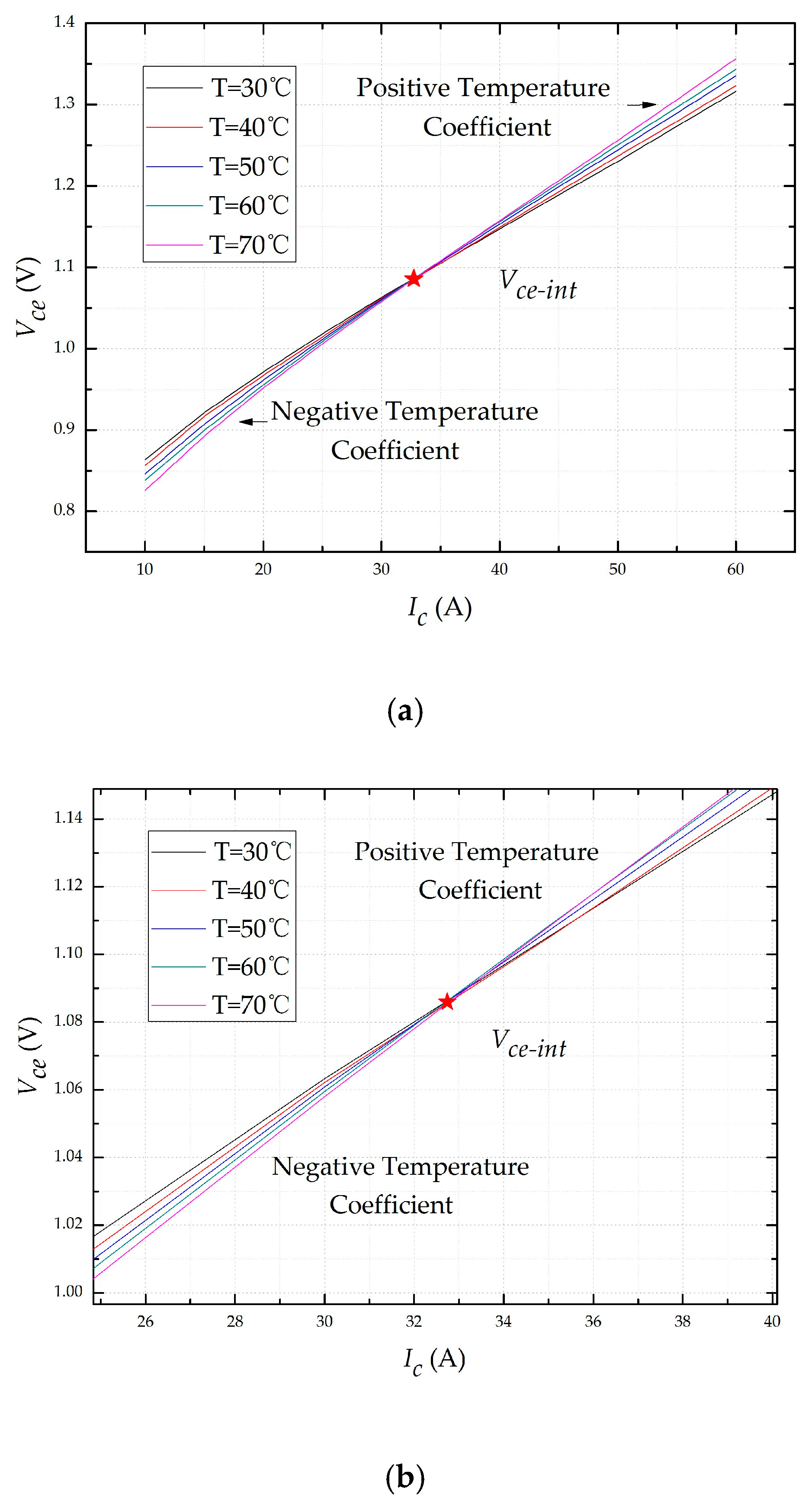
2.2. Influence of Temperature on On-State Voltage

On-state voltage is a temperature sensitive parameter in IGBT modules. The relationship between the on-state voltage and junction temperature is shown in Figure 1. There is an intersection point (Vce-int) in the voltage curves that indicates the influence of the collector current (Ic) and junction temperature (Tj). When Vce is less than Vce-int, Vce decreases as Tj increases and has a negative temperature coefficient. When Vce is greater than Vce-int, Vce behaves in a completely different manner and has a positive temperature coefficient.
Vce-th is the emitter-collector threshold voltage of the IGBT module. It remains constant as Ic increases, but decreases as Tj increases. The V–I characteristic curves for different junction temperatures are shown in Figure 2. A method introduced in reference [29] extracts Vce-th using the V–I characteristic curves. We adopted this method to acquire threshold voltages under different junction temperatures, as shown in Figure 3.
When the temperature is taken to be an independent variable, the dependent variable is the electrical resistivity of the metal. The thermal motion of the lattice inside the metal becomes more intensive with an increasing temperature, making it more chaotic. The obstruction of free electrons increases resistivity; thus, Rpackage has a positive temperature coefficient, and the resistance of Al bond wires (T0 = 228) at different junction temperatures can be obtained by Equation (4):
r k 75 ° C = r k θ T 0 + 75 T 0 + θ
where rk75°C is the resistance at 75 °C and rkθ is the resistance in standard temperature. In [29], Rpackage was extracted at the room temperature; thus, θ in Equation (4) was 25 °C and rkθ = 2.146 mΩ. Then, we obtained the Vpackage at different junction temperatures, as shown in Figure 4.
Von-chip is the on-state chip voltage which can be obtained from Equation (1). The collector current influence and the junction temperature were both considered, as shown in Figure 5.
An updated model was generated for the on-state voltage, showing the influences of Ic and Tj in order to obtain Vce under different conditions:
Vce (Ic,Tj) = Vce-th (Tj) + Von-chip (Ic,Tj) + Vpackage (Ic,Tj).

3. Measurements of On-State Voltage

3.1. Experimental Setup

Figure 6 shows the on-state voltage acquisition system. A high-power DC power source was connected in series with electronic loads on both sides of the collector-emitter. Another DC power source was connected to the gate-emitter of the IGBT module. A high-low temperature test chamber was used to achieve the temperature control for the IGBT module. The on-state voltage was measured using digital multimeters.
Figure 7 shows the semiconductor parameter test system, which is composed of a 2651A high power system sourcemeter, a 2636B system sourcemeter, an 8010 high power test device, and a microcomputer. The 8010 high power test device was used to connect 2600B and 2651A with the IGBT module and computer. Finally, V–I characteristic curves for the IGBT module were obtained by ACS software (V2.0 Release, Keithley Instruments, Cleveland, Ohio, USA).
A custom-made IGBT module (with the package removed) from Guoyang Electronics (WGL100B65F23) was used, as shown in Figure 8.

3.2. Acquisition of the Collector-Emitter Threshold Voltage

The experimental temperatures for the high-low temperature test chamber were set as 30 °C to 70 °C. The results are shown as V–I characteristic curves in Figure 2. The relationship between Vce and Ic became linear after a period of time when the IGBT module reached the on-state status. We adopted the method in Reference [29] to extract Vce-th at different junction temperatures. The results are as shown in Figure 3. Their relationships were fitted with the function; the detailed data are listed in Table 1. Vce-th has a negative temperature coefficient that can be approximated by a liner relationship. Thus, it was possible to obtain Vce-th at different junction temperatures with low errors after acquiring the function in Equation (6).
Vce-th (Tj) = −0.00112 × Tj + 0.67283

3.3. Acquisition of Package Voltage and On-State Chip Voltage

We tested the on-state voltage at different Ic and Tj values under an adequately heated condition using a high-low temperature test chamber. From the data we acquired from Figure 1, the intersection (Vce-int) was marked, and the collector current at that point was denoted as Ic-int. When Ic was less than Ic-int, Vce had a negative temperature coefficient because the Vce-th (negative temperature coefficient) represents the predominant part of the on-state voltage. When Ic was higher than Ic-int, the effect of the positive temperature coefficient (Von-chip, Vpackage) increased and became the main position in the constituent part of the on-state voltage, and Vce had a positive temperature coefficient.
The package resistance Rpackage remained constant as Ic increased and had a positive temperature coefficient. Combined with the operating conditions of the experimental environment, Equation (4) was updated to Equation (7). In addition, Rpackage was measured using the method described in reference [29]. This makes it possible to obtain Rpackage at different junction temperatures; Vpackage can be expressed by Equation (8). The curves of package voltage are shown in Figure 4:
R p a c k a g e   ( T j ) = R p a c k a g e   ( T j = 25 ° C ) × 228 + T j 228 + 25
V p a c k a g e   ( I c , T j ) = R p a c k a g e   ( T j ) × I c .
Von-chip was obtained after acquiring the information of Vce and Vpackage, as shown in Figure 5. It had a positive temperature coefficient and increased as Ic increased. In this paper, we defined FVon-chip (Ic,Tj) to describe the on-state chip voltage at any collector current and junction temperature. The data we acquired were imported into MATLAB software and the fitting function was expressed as
FVon-chip (Ic,Tj) = P00 + P10Ic + P01Tj + P20Ic2 + P11IcTj + P30Ic3 + P31Ic2Tj
where P00 is 0.1234, P10 is 0.00856, P01 is −0.0002294, P20 is −5.962 × 10⁻⁵, P11 is 3 × 10⁻⁵, P30 is 3.34 × 10⁻⁷, P31 is 5.976 × 10⁻⁸. The R-square value was 0.9988, indicating that the errors are within acceptable margins.

4. Prediction Result for Bond Wire Failure

4.1. Method of Applying On-State Voltage Separation Strategy to Predict Bond Wire Failure

Due to the differences in thermal expansion coefficients, IGBT module bond wires inevitably endure thermal stress under different working conditions. After a very large number of temperature cycles [30,31], the repeated stress–strain of the bond wires leads to the initiation and expansion of cracks at the solder joints, which eventually causes the bond wires to crack or liftoff. The destroyed bond wires accelerate the aging of other healthy bond wires and finally cause IGBT module failure.
Moreover, the aging of the bond wires increases the package resistance, Rpackage, and on-state voltage, Vce. It is difficult to avoid fluctuations of Ic and Tj across the collector-emitter in the IGBT module, which should be eliminated when considering the bond wire aging effect on the on-state voltage.
Table 2 shows the influences of Ic, Tj, and aging on each part of the on-state voltage mentioned in Section 2. It can be seen from Table 2 that Vpackage is the unique factor reflecting bond wire aging except for Vce and serves as the origin of the increase in on-state voltage in the aging process of bond wires.
We then applied the separation strategy of on-state voltage to IGBT module bond wire failure prediction, as shown in Figure 9. Vce-mea is the on-state voltage measured under on-line conditions, and Vpackage-cal is the package voltage calculated using Equation (10) under the same conditions after acquiring Ic and Tj information. Vpackage-hea, Vpackage-2liftoff, and Vpacakge-4liftoff are the package voltages measured under off-line conditions (healthy, two bond wires liftoff, and four bond wires liftoff, respectively):
Vpackage-cal = Vce-meaVce-th (Tj) − Von-chip (Tj, Ic).
According to the on-state voltage separation strategy proposed by us, Vce was separated into Vce-th and Von-chip, which remained constant throughout the IGBT module bond wire aging process, and Vpackage which is the dependent variable in the process of bond wire aging. This separation strategy eliminates the interference of the independent variable and makes it possible to directly observe the voltage change caused by the bond wire failure.

4.2. Accuracy of the Diagnosis Strategy in Predicting Bond Wire Failure

To study the parametric characteristics of the IGBT module after a bond wire failure, a reasonable method is necessary to accelerate the bond wire aging process. Power cycling [32] and bond wire cut off [33] are widely used in the aging of IGBT modules. The latter method simulates the different aging degrees by changing the sheared number of the bond wires and visually reflects the failure. What is more, the essence of IGBT module bond wire failure is the disconnection of two hitherto connected parts. Thus, applying the cut-off method to IGBT module bond wire failure simulation has no influence on the failure prediction scheme proposed in this paper. Therefore, this method was adopted to accelerate the aging process of bond wires.
In this paper, the on-state voltages for two bond wires cut off and four bond wires cut off were set as critical points between the different aging periods. The diagnostic strategy is shown in Figure 9 and examples are provided to verify the accuracy of the on-state voltage separation strategy in predicting the IGBT module bond wire failure.
Rpackage has an obvious change in the bond wire aging process for the IGBT module. To acquire a precise standard for bond wire aging prediction, Rpackage was tested using the equipment shown in Figure 6. The junction temperature was set to 25 °C, and Vce-th was obtained by Equation (6). The voltage supplied by a high-power source was increased gradually until the IGBT module reached the on-state status (Vce > Vce-th). The experimental data are presented in Table 3. Thus, Vpackage-2liftoff and Vpackage-4liftoff at different Tj (30–70 °C) were calculated as standards of bond wire failure prediction. The detailed data are shown in Figure 10 (Ic = 75A).
To demonstrate the accuracy of our prediction method, different numbers of bond wires were cut off (1,3,5) and the results are shown for the following cases:

4.2.1. Case 1: One Bond Wire Cut Off, Ic = 75A, Tj = 50 °C

The IGBT module with one bond wire cut-off was tested, and the diagnosis process shown in Figure 11 was applied. The electronic load in Figure 6 was substituted with a high-power load (600 V/240 A/12 kW) to acquire a higher collector current (75 A). The diagnosis strategy shows that Vpackage-cal is higher than Vpackage-hea, but lower than Vpackage-2liftoff. Thus, it can be classified as the initial stage of the bond wire failure, the same status as the real aging process.

4.2.2. Case 2: Three Bond Wires Cut Off, Ic = 75A, Tj = 60 °C

We then tested the on-state voltage of another IGBT module (three bond wires cut off). With Ic = 75 A and Vce-mea = 1.6091 V, Equations (6), (9) and (10) yield Vce-th = 0.6056 V, Von-chip = 0.6898 V, Vpackage-cal = 0.3137 V, respectively, as shown in Figure 10. The diagnosis strategy shows it can be classified as the middle stage of the bond wire failure, the same status as the real aging process. Thus, the aging process of bond wire can be predicted accurately at different junction temperatures using the proposed diagnosis strategy.

4.2.3. Case 3: Three Bond Wires Cut Off, Ic = 20 A, Tj = 60 °C

The research presented in this paper shows that Rpackage is in the milli-ohm range, resulting in a low proportion of on-state voltage even under high current conditions. When it comes to low current conditions, Vpackage will be lower than before. It is necessary to demonstrate the applicability of our diagnosis strategy under low current conditions.
When Ic is 20 A, Vce-mea is 0.9803 V, Vce-th is 0.6056 V, Von-chip is 0.2990 V, and Vpackage is 0.0757 V which is marked in Figure 12. Thus, the middle stage of the bond wire failure can be diagnosed accurately by the proposed strategy even under low current conditions.

4.2.4. Case 4: Five Bond Wires Cut Off, Ic = 75 A, Tj = 70 °C

We finally tested an IGBT module with five bond wires cut off. It worked normally with a higher on-state voltage under the same condition as Vpackage-4liftoff in the low current range. However, as the current increased, the heat generated in the bond wires caused the complete failure of the bond wire as shown in Figure 13: the remaining healthy bond wires lifted off rapidly under high current conditions, which is the final stage of bond wire failure.

5. Conclusions

In this paper, an IGBT module on-state voltage separation strategy based on physical structure has been proposed. This method considers the effect of collector current and junction temperature during the on-state status and gives a method to calculate for each part under different conditions.
This separation strategy eliminates the interference of the independent variable and makes it possible to directly observe the voltage changes caused by the bond wire failure. The experimental results demonstrate the effectiveness of the proposed diagnosis strategy in accurately predicting the bond wire failure stage in IGBT module under different conditions.

Author Contributions

Operation of the experiments, analysis and writing of the paper, Q.K.; guidance of theoretical analysis and writing, M.D.; guidance and optimizing of experiments, K.W.; modification of manuscript, Z.O. and W.G.H.

Funding

This research was funded by the “New Energy Vehicle” Key Special Project of the National Key Research and Development Plan [No. 2017YFB0102500]”and “the Tianjin Natural Science Foundation of China [No. 17JCYBJC21300]”.

Conflicts of Interest

The authors declare no conflict of interest.

References

  1. Li, H.; Hu, Y.; Liu, S.; Li, Y.; Liao, X.; Liu, Z. An Improved Thermal Network Model of the IGBT Module for Wind Power Converters Considering the Effects of Base Plate Solder Fatigue. IEEE Trans. Device Mater. Reliab. 2016, 16, 570–575. [Google Scholar] [CrossRef]
  2. Alhmoud, L. Reliability Improvement for a High-Power IGBT in Wind Energy Applications. IEEE Trans. Ind. Electron. Control Instrum. 2018, 65, 7129–7137. [Google Scholar] [CrossRef]
  3. Ji, B.; Pickert, V.; Cao, W.; Zahawi, B. In Situ Diagnostics and Prognostics of Wire Bonding Faults in IGBT Modules for Electric Vehicle Drives. IEEE Trans. Power Electron. 2013, 28, 5568–5577. [Google Scholar] [CrossRef] [Green Version]
  4. Song, Y.; Wang, B. Evaluation Methodology and Control Strategies for Improving Reliability of HEV Power Electronic System. IEEE Trans. Veh. Technol. 2014, 63, 3661–3676. [Google Scholar] [CrossRef]
  5. Zahedi, B.; Norum, L.E. Modeling and Simulation of All-Electric Ships With Low-Voltage DC Hybrid Power Systems. IEEE Trans. Power Electron. 2013, 28, 4525–4537. [Google Scholar] [CrossRef]
  6. Cao, W.; Mecrow, B.C.; Atkinson, G.J.; Bennett, J.W.; Atkinson, D.J. Overview of Electric Motor Technologies Used for More Electric Aircraft (MEA). IEEE Trans. Ind. Electrons. 2012, 59, 3523–3531. [Google Scholar]
  7. Yang, S.; Bryant, A.; Mawby, P.; Xiang, D.; Ran, L.; Tavner, P. An industry-based survey of reliability in power electronic converters. IEEE Trans. Ind. Appl. 2011, 47, 1441–1451. [Google Scholar] [CrossRef]
  8. Blaabjerg, F.; Ma, K. Future on Power Electronics for Wind Turbine Systems. IEEE J. Emerg. Select. Topic. Power. Elect. 2013, 1, 139–152. [Google Scholar] [CrossRef]
  9. Bie, X.; Qin, F.; An, T.; Zhao, J.; Fang, C. Numerical simulation of the wire bonding reliability of IGBT module under power cycling. In Proceedings of the International Conference on Electronic Packaging Technology, Harbin, China, 16–19 August 2017; pp. 1396–1401. [Google Scholar]
  10. Fazeli, S.M.; Jovcic, D.; Hajian, M. Laboratory Demonstration of Closed-Loop 30KW, 200V/90V IGBT-Based LCL DC/DC Converter. IEEE Trans. Power Delivery. 2018, 33, 1247–1256. [Google Scholar] [CrossRef]
  11. Luo, H.; Wang, X.; Zhu, C.; Li, W.; He, X. Investigation and Emulation of Junction Temperature for High-Power IGBT Modules Considering Grid Codes. IEEE J. Emerg. Select. Topic. Power. Elect. 2018, 6, 930–940. [Google Scholar] [CrossRef]
  12. Bahman, A.S.; Ma, K.; Ghimire, P.; Iannuzzo, F.; Blaabjerg, F. A 3-D-Lumped Thermal Network Model for Long-Term Load Profiles Analysis in High-Power IGBT Modules. IEEE J. Emerg. Select. Topic. Power. Elect. 2016, 4, 1050–1063. [Google Scholar] [CrossRef]
  13. Niu, H. The Effect of Load Properties on the Reliability of Machine Drives—The Temperature and Stress Analysis of Power Module Bond Wires. In Proceedings of the IEEE Energy Conversion Congress and Exposition, Cincinnati, OH, USA, 1–5 October 2017; pp. 2533–2539. [Google Scholar]
  14. Choi, U.; Blaabjerg, F.; Jørgensen, S. Study on Effect of Junction Temperature Swing Duration on Lifetime of Transfer Molded Power IGBT Modules. IEEE Trans. Power Electron. 2017, 32, 6434–6443. [Google Scholar] [CrossRef]
  15. Bahman, A.S.; Iannuzzo, F.; Uhrenfeldt, C.; Blaabjerg, F.; Stig, M. Modeling of Short-Circuit-Related Thermal Stress in Aged IGBT Modules. IEEE Trans. Ind. Appl. 2017, 53, 4788–4795. [Google Scholar] [CrossRef] [Green Version]
  16. Smet, V.; Forest, F.; Huselstein, J.-J.; Rashed, A.; Richardeau, F. Evaluation of Vce Monitoring as a Real-Time Method to Estimate Aging of Bond Wire-IGBT Modules Stressed by Power Cycling. IEEE Trans. Ind. Electron. 2013, 60, 2760–2770. [Google Scholar] [CrossRef]
  17. Haque, M.S.; Choi, S.; Baek, J. Auxiliary Particle Filtering-Based Estimation of Remaining Useful Life of IGBT. IEEE Trans. Ind. Electron. 2018, 65, 2693–2703. [Google Scholar] [CrossRef]
  18. Peng, Y.; Zhou, L.; Du, X.; Sun, P.; Wang, K.; Cai, J. Junction temperature estimation of IGBT module via a bond wires lift-off independent parameter VgE-np. IET Power Electron. 2018, 11, 320–328. [Google Scholar] [CrossRef]
  19. Wang, Z.; Tian, B.; Qiao, W.; Qu, L. Real-Time Aging Monitoring for IGBT Modules Using Case Temperature. IEEE Trans. Ind. Electron. 2016, 63, 1168–1178. [Google Scholar] [CrossRef]
  20. Sun, P.; Gong, C.; Du, X.; Peng, Y.; Wang, B.; Zhou, L. Condition Monitoring IGBT Module Bond Wires Fatigue Using Short-Circuit Current Identification. IEEE Trans. Power Electron. 2017, 32, 3777–3786. [Google Scholar] [CrossRef]
  21. Haque, M.S.; Baek, J.; Herbert, J.; Choi, S. Prognosis of Wire Bond Lift-Off Fault of an IGBT Based on Multisensory Approach. In Proceedings of the IEEE Applied Power Electronics Conference and Exposition, Long Beach, CA, USA, 20–24 March 2016; pp. 3004–3011. [Google Scholar]
  22. Han, J.; Ma, M.; Chu, K.; Zhang, X.; Lin, Z. In-Situ Diagnostics and Prognostics of Wire Bonding Faults in IGBT Modules of Three-Level Neutral-Point-Clamped Inverters. In Proceedings of the IEEE 8th International Power Electronics and Motion Control Conference, Hefei, China, 22–26 May 2016; pp. 3262–3267. [Google Scholar]
  23. Pedersen, K.B.; Kristensen, P.K.; Pedersen, K.; Uhrenfeldt, C.; Munk-Nielsen, S. Vce as Early Indicator of IGBT Module Failure Mode. In Proceedings of the IEEE International Reliability Physics Symposium, Monterey, CA, USA, 2–6 April 2017; pp. FA-1.1–FA-1.6. [Google Scholar]
  24. Ghimire, P.; Bęczkowski, S.; Munk-Nielsen, S.; Rannestad, B.; Thøgersen, P.B. A Review on Real Time Physical Measurement Techniques and Their Attempt to Predict Wear-Out Status of IGBT. In Proceedings of the European Conference on Power Electronics and Applications, Lille, France, 2–6 September 2013; pp. 1–10. [Google Scholar]
  25. Hoeer, M.; Weiss, F.; Bernet, S. Online Collector-Emitter Saturation Voltage Measurement for the In-Situ Temperature Estimation of a High-Power 4.5 kV IGBT Module. In Proceedings of the European Conference on Power Electronics and Applicationsin, Warsaw, Poland, 11–14 September 2017; pp. 1–9. [Google Scholar]
  26. Degrenne, N.; Mollov, S. On-line Health Monitoring of Wire-Bonded IGBT Power Modules Using On-State Voltage at Zero-Temperature-Coefficient. In Proceedings of the International Exhibition and Conference for Power Electronics, Intelligent Motion, Renewable Energy and Energy Management, Nuremberg, Germany, 5–7 June 2018; pp. 1–7. [Google Scholar]
  27. Choi, U.; Blaabjerg, F. Separation of Wear-Out Failure Modes of IGBT Modules in Grid-Connected Inverter Systems. IEEE Trans. Power Electron. 2018, 33, 6217–6223. [Google Scholar] [CrossRef]
  28. Halick, M.S.M.; Kandasamy, K.; Jet, T.K.; Sundarajan, P. Online Computation of IGBT On-State Resistance for Off-Shelf Three-Phase Two-Level Power Converter Systems. Microelectron. Reliab. 2016, 64, 379–386. [Google Scholar] [CrossRef]
  29. Kong, Q.; Du, M.; Ouyang, Z.; Wei, K.; Hurley, W.G. A Model of the On-State Voltage across IGBT Modules Based on Physical Structure and Conduction Mechanisms. Energies 2019, 12, 851. [Google Scholar] [CrossRef]
  30. Smet, V.; Forest, F.; Huselstein, J.J.; Richardeau, F.; Khatir, Z.; Lefebvre, S.; Berkani, M. Ageing and Failure Modes of IGBT Modules in High-Temperature Power Cycling. IEEE Trans. Ind. Electron. 2011, 58, 4931–4941. [Google Scholar] [CrossRef]
  31. Tounsi, M.; Oukaour, A.; Tala-Ighil, B.; Gualous, H.; Boudart, B.; Aissani, D. Characterization of high-voltage IGBT module degradations under PWM power cycling test at high ambient temperature. Microelectron. Reliab. 2010, 50, 1810–1814. [Google Scholar] [CrossRef]
  32. Ji, B.; Song, X.; Sciberras, E.; Cao, W.; Hu, Y.; Pickert, V. Multiobjective Design Optimization of IGBT Power Modules Considering Power Cycling and Thermal Cycling. IEEE Trans. Power Electron. 2015, 30, 2493–2504. [Google Scholar] [CrossRef] [Green Version]
  33. Wei, K.; Du, M.; Xie, L.; Li, J. Study of Bonding Wire Failure Effects on External Measurable Signals of IGBT Module. IEEE Trans. Device Mater. Reliab. 2014, 14, 83–89. [Google Scholar]
Figure 1. Relationship between on-state voltage (Vce) and junction temperature (Tj): (a) The complete characteristic curves; (b) the enlarged view near an intersection point (Vce-int).
Energies 12 01791 g001
Figure 2. V–I characteristic curves at different junction temperatures: (a) The whole part of the characteristic curves; (b) the enlarged view near Vce-th.
Energies 12 01791 g002
Figure 3. Threshold voltages at different junction temperatures.
Energies 12 01791 g003
Figure 4. Package voltages at the different junction temperatures.
Energies 12 01791 g004
Figure 5. On-state chip voltages at different junction temperatures.
Energies 12 01791 g005
Figure 6. The on-state voltage acquisition system.
Energies 12 01791 g006
Figure 7. The semiconductor parameter test system.
Energies 12 01791 g007
Figure 8. The insulated gate bipolar transistor (IGBT) module used in the experiment.
Energies 12 01791 g008
Figure 9. The method of applying on-state voltage separation strategy to bond wire failure prediction.
Energies 12 01791 g009
Figure 10. Package voltage at different junction temperature (Ic = 75 A).
Energies 12 01791 g010
Figure 11. The diagnosis process for IGBT module bond wire failure.
Energies 12 01791 g011
Figure 12. The package voltage at different junction temperatures (Ic = 20 A).
Energies 12 01791 g012
Figure 13. The final stage of bond wire failure.
Energies 12 01791 g013
Table 1. Vce-th extraction at different junction temperatures.
Junction Temperature (°C)abR-SquareVce-th (V)
305.46076−3.486510.998520.6384
405.15092−3.238110.997920.6286
505.3208−3.285350.99750.6174
605.32871−3.240460.998790.6081
705.34749−3.204710.998780.5929
Table 2. Different factors in the components of on-state voltage.
VoltageIc (Increases)Tj (Increases)Bond Wire Failure
Vce-th----------
Von-chip-----
Vpackage
Table 3. Rpackage at different aging periods (Tj= 25 °C).
Voltage (V)Vce (V)Ic (A)Vce-th (V)Rpackage (mΩ)
2 bond wires liftoff0.64630.48770.64483.0757
4 bond wires liftoff0.64780.53830.64485.5731

