Article

Experimental Validation of a Numerical Model of a Ventilated Façade with Horizontal and Vertical Open Joints

by
María Nuria Sánchez
1,
Emanuela Giancola
1,*,
Eduardo Blanco
2,
Silvia Soutullo
1 and
María José Suárez
2
1
Department of Energy, Centro de Investigaciones Energéticas, Medioambientales y Tecnológicas, 28040 Madrid, Spain
2
EDZE (Department of Energy), Universidad de Oviedo, 33271 Gijón (Asturias), Spain
*
Author to whom correspondence should be addressed.
Energies 2020, 13(1), 146; https://doi.org/10.3390/en13010146
Submission received: 5 November 2019 / Revised: 19 December 2019 / Accepted: 23 December 2019 / Published: 27 December 2019
(This article belongs to the Special Issue Building Energy Performance Measurement and Analysis)

Abstract

:
Commercial and residential building is one of the four major final energy consumption and end-use sectors. In this sector, cooling loads represent an important part of the energy consumption, and therefore, they must be minimized, improving the energy efficiency of buildings. Ventilated façades are one of the most widely used passive elements that are integrated into buildings, precisely with the aim of reducing these loads. This reduction is due to the airflow induced in the air cavity by the buoyancy forces, when the solar radiation heats the outer layer of the façade. In the open joint ventilated facades (OJVF), ventilation is attained through the open joints between the panels composing the outer layer. Despite the steadily growing research in the characterization of this type of system, few studies combine the numerical modelling of OJVF with experimental results for the assessment of the airflow in the ventilated cavities. This paper experimentally validates a numerical simulation model of an OJVF. Firstly, the façade performance has been experimentally assessed in a laboratory model determining the temperatures in the panels and air gap and measuring the flow field at the gap using particle image velocimetry (PIV) techniques. Secondly, a numerical model has been developed using advanced Computational Fluid Dynamics (CFD) simulation tools. Finally, an experimental validation of the numerical model has been done. Experimental and numerical results are compared in different planes inside the ventilated cavity. The discrete ordinates (DO) radiation model and the k-ε renormalisation group (RNG) turbulence model better adjust the simulated results to the experimental ones.

1. Introduction

The growing interest in the sustainable development of cities is enhanced by current environmental threats, such as resource shortages and the impact of climate change. Taking into account this promotion of inclusive and dynamic urban growth, different European [1,2], American [3,4] and Asian [5] governments have adopted several directives and policies to construct more energy efficient buildings. Also, the use of effective solutions to increase the energy performance of buildings is promoted [6,7,8], with the final goal of achieving Nearly Zero-Energy Buildings (NZEBs) [9]. The design of NZEBs requires the integration of multiple passive techniques into the building structure. The term “passive design” refers to design approaches that improve thermal comfort without energy consumption, using for example reasonable building orientation or improved thermal performance. Some examples of passive building designs are based on enhancing the natural ventilation [10], the application of trombe walls [11] or ventilated façades [12].
The efficient use of passive strategies involves an optimization process done through simulation methods [13]. The optimal method to quantify the energy performance of buildings depends on the information and resources available [14]. Engineering methods are based on the physical equations of the building to characterize its energy performance. By contrast, statistical methods rely on the data collection inside a building to obtain its usage patterns. Finally, hybrid methods are based on the combination of mathematical equations fed by real data. There is a large number of engineering models available, but the most common used are: nodal, zonal and Computational Fluid Dynamics (CFD). The differences between them are the number of control volumes required, the mathematical equations proposed and the methodology used to solve the equations. Nodal models are mainly used to assess the global behaviour of the building by solving the energy transfer equations [15]. CFD models are specially designed to evaluate convective processes in buildings by solving the Navier—Stokes equations, since ventilation flows are complex [16]. These models are widely used to model indoor and outdoor airflows [17,18], heat transfer [19,20] and contaminant transport [21].
The construction industry is mainly focused on different actions to promote innovative and sustainable solutions in new and existing buildings, emphasizing the building envelope [22,23,24], mainly the façades, which play a substantial role in the energy saving of the buildings [25,26,27,28,29]. Along this line, Halawa et al. [30] presented a review addressing different options to optimize the performance of building façades in hot and humid climates, drawing attention to innovative solutions. This review highlighted better thermal insulation and ventilated façade systems as the most relevant and appropriate ones.
The ventilated façades are characterized mainly by the presence of a ventilated channel created between the internal and external layers of the building envelope. An efficient design of these systems has to carefully consider functional and performance concerns, as well as aesthetic possibilities and architectural issues. In this regard, Bikas et al. [31] made a state-of-the-art analysis of the legal, technical, social and financial requirements and specifications that ventilated façades should fulfil across Europe, underlining the feasibility of these systems.
Many studies assess the energy saving potential of these façades through their insulation characteristics [32,33,34] and its hygrothermal performance and moisture control [35,36]. Other studies perform both experimental and numerical analyses to characterize the airflow in the ventilated façades [37,38,39,40]. Regarding the experimental techniques, Giancola et al. [41] summarize the existing methods (real scale, test cell and/or laboratory application), analysing their capabilities and limitations with special emphasis on their scope.
Due to the great diversity of names for this façade configuration (ventilated walls, double skin façades, rainscreen or ventilated façades, and so on), it is important to specify that this work is focused on opaque ventilated façades (OVF). Regarding this type of façade, Ibañez-Puy et al. [42] carried out a review of recent studies addressing its thermal and energy performance. Other authors experimentally compare different OVF options [43]. Some studies assess the influence of design [44,45] and climate conditions [46,47,48,49] on energy savings, giving key strategies for the system efficiency. Currently, photovoltaic systems are integrated in ventilated façades, and experimental [50], numerical [51] and combined studies [52,53] have been carried out for these kinds of solutions. Other studies evaluate the impact of phase change materials [54], or air control temperature [55] on the ventilated façade performance.
In this work, a specific opaque ventilated façade called “Open Joint Ventilated Façades” (OJVF) is evaluated as a constructive strategy to enhance the energy efficiency in both new and existing buildings. This building element creates a ventilated air chamber between the exterior cladding and the isolation layer fixed to the external wall of the building. Its external coat is composed of multiple panels separated by open joints and anchored to the building by means of a metallic structure.
Scientific literature about OJVFs is very scarce, although there are some papers analysing certain characteristics also applicable to these façades, for example, studies evaluating different panel materials (ceramic [56], clay, stone [57], or even metal [58,59]) or the effect of the climate [60]. There are some articles considering the influence of the geometry, although they do not provide specific data [61,62].
The work on the performance prediction of ventilated façades has mostly focused on the use of Building Performance Simulation (BPS) as a tool for analysis. Although BPS tools have been developed to replicate the overall behaviour of a building, they are geared towards modelling traditional building envelope components. However, Loonen et al. [63] highlight the limited capability of BPS to accurately quantify the performance of adaptive building envelope technologies, considering these façades by default as ordinary ventilated or slightly ventilated air chamber façades, without taking into account their performance against solar radiation. The commercial building energy simulation software, such as Visual DOE, TRNSYS or Energy Plus, has not yet included a general-purpose model to simulate these façade systems. In the specific case of the OJVF, the description of the heat and mass transfer phenomena confirms the fact that the complexity of the fluid flow in the regions near the joints and along the ventilated cavity defies analytical methods. The use of advanced fluid dynamic simulation techniques is compulsory because of their high capacity to achieve a close description of the details of the internal air flows and heat transfer phenomena [64].
Comparing numerical methods with empirical assessments, the first ones are better tools for system evaluations considering different geometries and boundary conditions. This is a direct consequence of the high cost of resources in both staff and time required for experimental tests. However, before addressing these specific studies on this type of ventilated façades, the authors of this paper have focused on defining a simulation procedure to determine the performance of such systems and characterize their behaviour.
This paper presents the development and experimental validation of a numerical model of OJVFs with horizontal and vertical open joints. The airflow in the ventilated cavity of these systems against the solar radiation has been characterized in experimentally-controlled laboratory conditions. In these test conditions, the main external variables affecting the performance of the façade, such as air temperature, humidity, wind velocity and panels heating, have been measured and controlled. Pseudo steady state conditions have been achieved during experimental tests, setting specific and appropriate boundary conditions with predefined experimental cases of study. This helped to evaluate, e.g., the individual influence of a specific parameter such as the panel heat on the ventilation rate. Previous numerical models of OJVF being experimentally validated have been developed in real conditions [56], measuring thermal parameters such as air temperature or heat fluxes, but without measuring the airflow motion inside the camera. In real conditions, environmental factors cannot be regulated nor fixed during the measuring test due to the stochastic behaviour of the wind, changes in panel heat or in air temperature and humidity. So, it is not possible to guarantee stable outdoor boundary conditions during the measuring campaign in order to isolate the effect of relevant variables on the airflow behaviour. Additionally, the experimental determination of the velocity field inside the ventilated cavity is nearly impossible in a real façade, but it can be made using non-intrusive methodologies in appropriate laboratory models.

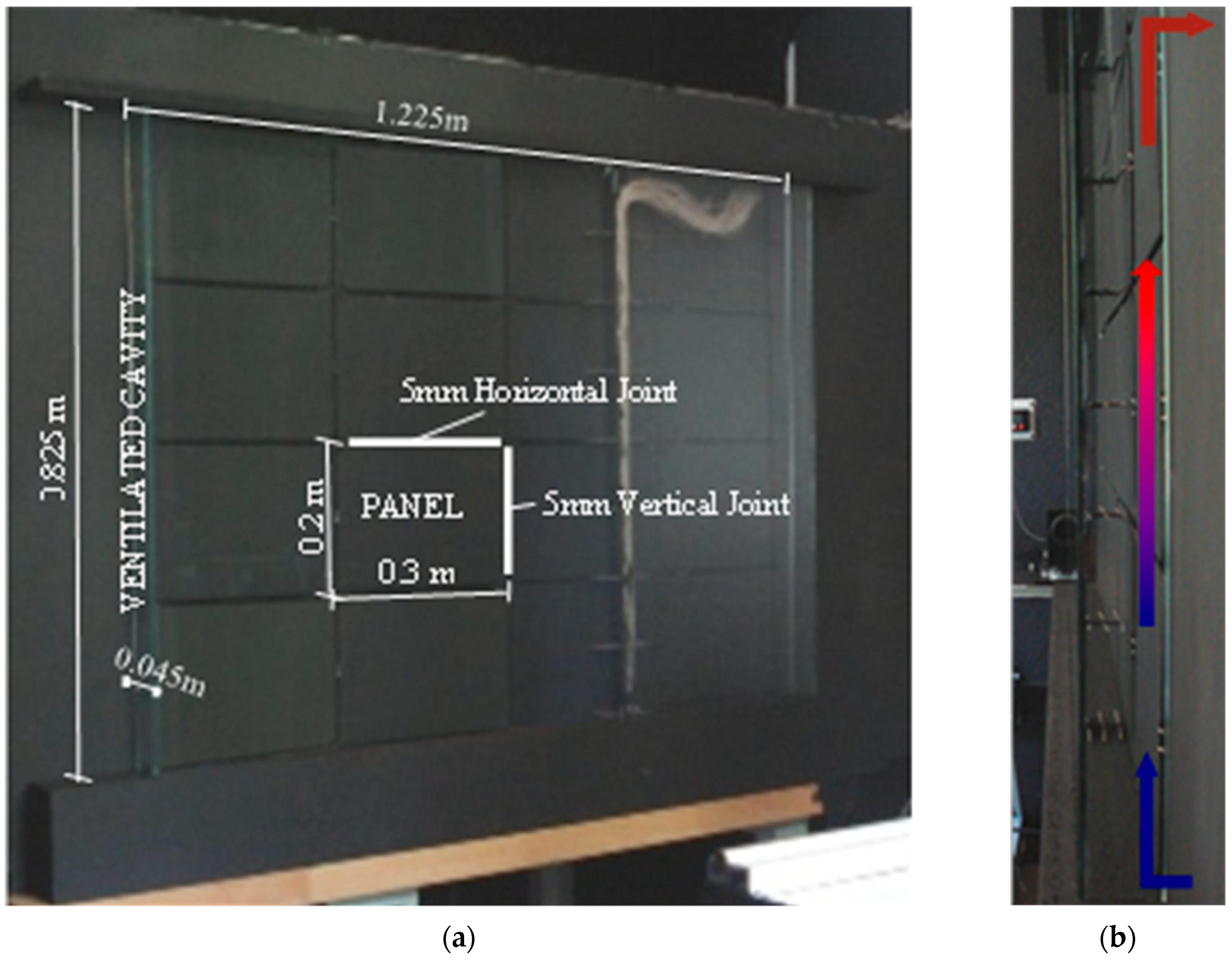
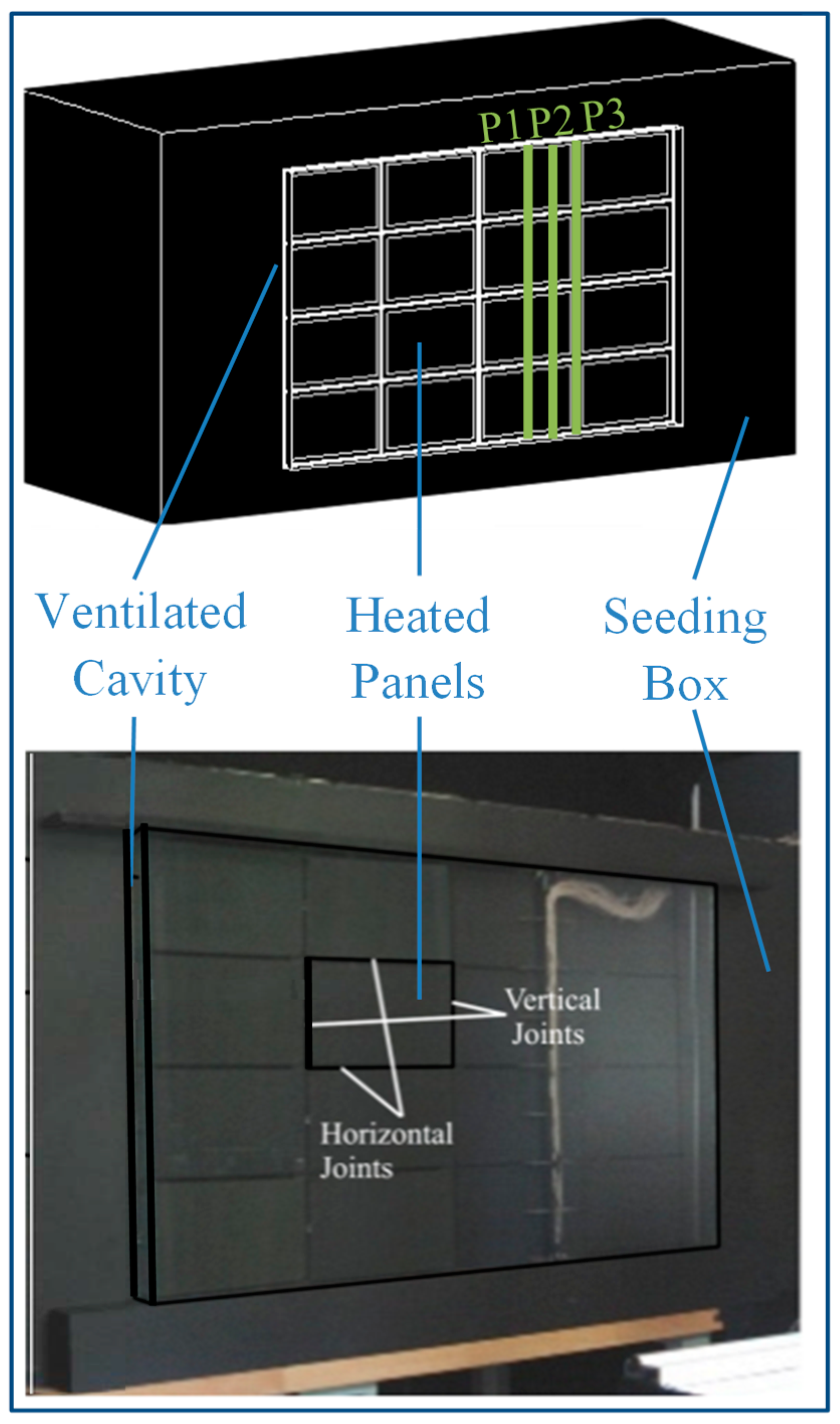
2. Materials and Methods: Experimental Test Bench

Before addressing the numerical model developed in this research, this section describes the assembly and equipment utilized in the experimental tests. A laboratory model of a ventilated façade has been designed to study the thermal and fluid-dynamic performance of this type of building elements in the function of the solar radiation conditions [65]. It has the same composition as real façades with three main layers: an outer opaque layer, an inner wall and an air cavity between them. The global dimensions are 0.825 m × 1.225 m (High × Wide) with a ventilated cavity of 0.045 m. The panels of the exterior layer (0.3 m × 0.2 m) are landscape oriented and symmetrically distributed in 4 rows and 4 columns, with both horizontal and vertical open joints of 5 mm (Figure 1). Table 1 displays a summary of the most relevant physical properties.
Nonintrusive laser optical measurement techniques have been applied for the flow visualization inside the air cavity of the façade and for obtaining instantaneous velocity fields. The experimental set up of the laboratory has been based on previous studies developed applying the 2D-particle image velocimetry (PIV) technique to a horizontal open joint ventilated facades (OJVF) model [66,67,68]. This technique was applied to characterize the natural convection phenomena inside the ventilated cavity by determining the in-plane velocity components [69]. However, in this case, the OJVF model analyzed has both horizontal and vertical joints, so the Stereo–PIV technique has been applied to obtain the three-dimensional velocity field. The laser measurements are made from the interior room side of the façade. The brick inner skin in a real façade has been substituted by a clear glass, allowing the laser illumination in planes perpendicular to the façade. Three planes were experimentally evaluated: P1, P2 and P3 (Figure 2b). The first plane P1 is at a distance of 150 mm from the vertical joint (½ of panel width), the second one P2 is at a distance of 75 mm (¼ of panel width) and the third plane coincides with the vertical joint. The two cameras necessary for the stereo measurements are situated at 45° on either side of the laser plane (Figure 2a).
The heating effect of the solar radiation on the panels has been simulated by electric heating mats adhered to them. Thermal measurements have been performed using infrared thermography and temperature probes. The Figure 3a shows the surface temperature resistance temperature detector (RTD) sensors placed in the centre of the panels, and the thermocouples’ location inside the air cavity is showed on the Figure 3b. Position coordinates x/W and y/H are normalized by the cavity width (W = 0.045 m) and height (H = 0.825 m).

3. Numerical Simulation Model

A numerical model of an OJVF has been developed using the Computational Fluid Dynamics (CFD) code FLUENT. This code allows the simultaneous analysis of heat transmission and fluid-dynamic problems, solving the Navier—Stokes equations (including the energy equation), with the finite volumes method. The CFD code solves the equations in a series of points of geometry (spatial discretization), transforming differential equations into algebraic equations using numerical methods.

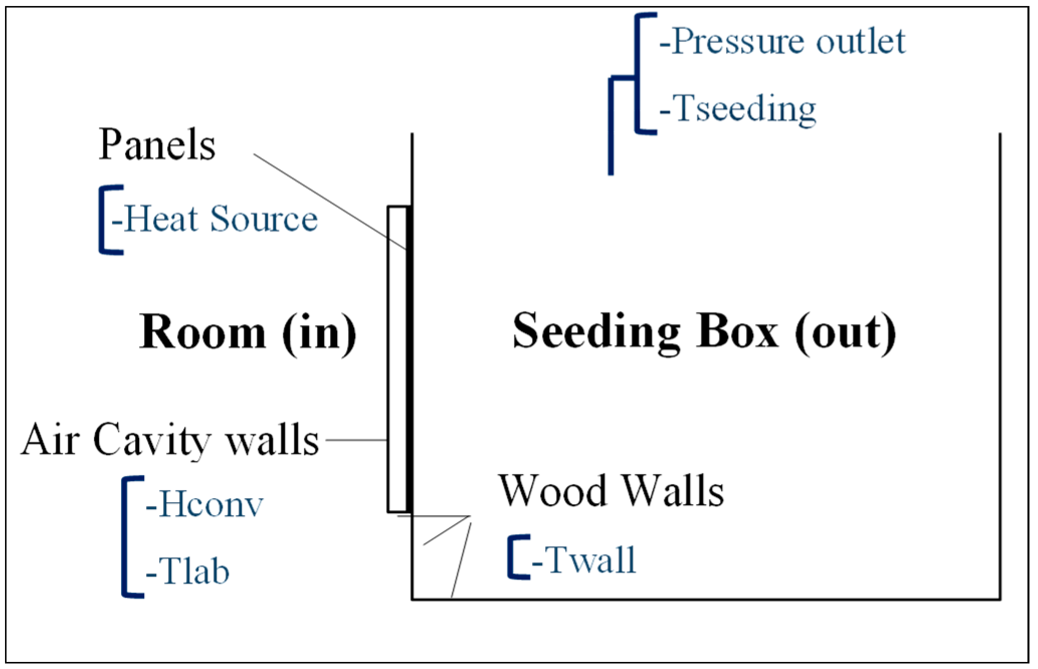
3.1. Description of the Geometry and the Boundary Conditions

The model has been developed taking into account previous studies [70,71]. It has a three-dimensional geometry, and for the validation purposes, represents the laboratory test bench taking special care with the horizontal and vertical joints (Figure 4). The boundary conditions in both interior (Room) and exterior (Seeding Box) have been selected according to the experiments as shown in Figure 5. The external air has constant hydrostatic pressure (atmospheric) and enters the cavity at exterior air temperature. The same temperature has been considered for radiation exchange with the environment. The radiation could be introduced in two different ways: (a) by including the absorbed radiation as an internal source of the panels, or (b) by entering the solar radiation into the domain by using semi-transparent wall boundary conditions [72]. Regarding the experimental setup described in Section 2, the first approach has been applied. Only the incident radiation perpendicular to the façade component has been considered.
The physical properties of the materials are also the same as the experiments (Table 1); the emissivity of the opaque walls has been taken as 0.95 and that of the glazed surfaces as 0.9. The heating effect of the solar radiation is also simulated by heating surfaces at the exterior panels. The radiation value for the validation has been selected as 460 W/m2 (summer conditions), corresponding to Ra = 1.0 × 10⁹.

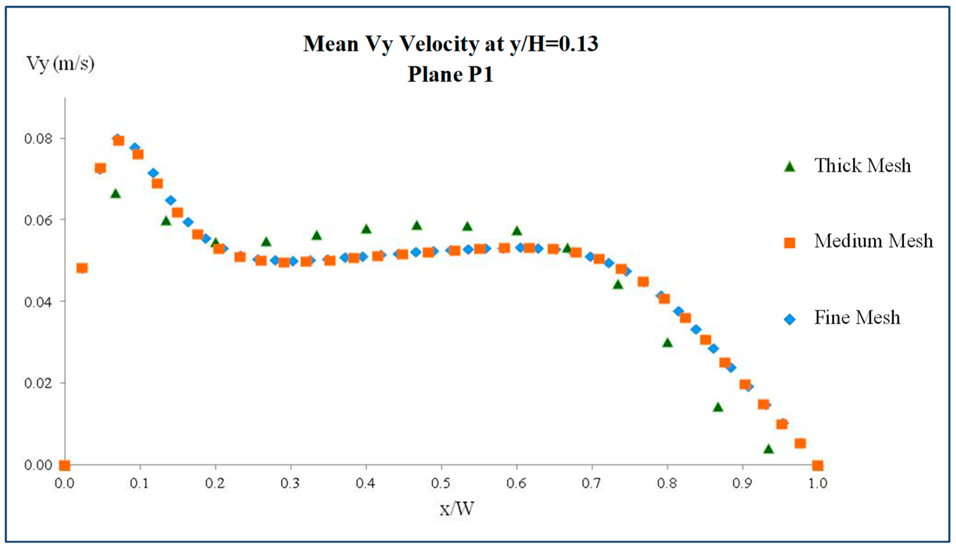
3.2. Main Characteristics of the Mesh

Regarding the mesh, a structured hexahedral mesh has been used in the panels and the cavity, and an unstructured one in the seeding box. The geometry of the panels and the cavity fits a structured mesh, but due to the small size of the joints, it is necessary to obtain a gradual distribution of the cells to maintain the total number of cells small enough for a viable calculation. This is also the reason for an unstructured mesh in the seeding box, so that in the absence of obstacles the mesh cells size can be increased more progressively. Figure 6 shows a detail of the mesh, specifically the refinement at the panel borders and the joints.
A sensitivity analysis of the mesh has been performed with cases varying in range between five hundred thousand and one million cells. Table 2 summarizes the parameters of the three main meshes employed.
Figure 7 shows a comparison of the air velocity results inside the cavity for these meshes. The velocity component (Vy) has been evaluated, for Ra = 1.0 × 10⁹ conditions, in the plane P1 at a normalized height of y/H = 0.13. The plane P1 is at a distance of 150 mm from the vertical joint (½ of panel width). y/H are position coordinates normalized by cavity width (W = 0.045 m) and height (H = 0.825 m). The value of 0.13 corresponds to the central height of the lowest panel. It has been observed that from eight hundred thousand cells upwards, the results hardly vary, so that mesh has been used for most of the calculations.
It has been proven that the medium mesh is also suitable to perform accurate calculations in the zones of the boundary layer. Figure 8 presents the values of the y+ parameter in the surfaces of both panels and back wall. This parameter is used in CFD to determine the nondimensional ratio between the wall cell size and the boundary layer. Values of y+ below one guarantee that the mesh near the wall is thin enough to solve the viscous and transitional sub-layers.

3.3. Main Characteristics of the CFD Models

In the study of the turbulence effects, as the ventilation flow inside the cavity is characterized by its turbulent regime, several 3D RANS models of one and two equations have been used and compared. Specifically, the Sparlat—Allmaras, k-ε Standard, k-ε RNG, k-ε REA, k-ω Standard and k-ω SST models have been tested.
The phenomenon of natural convection is based on the buoyancy forces created by the density differences due to the temperature gradients. Gravitational body forces have been included within the momentum equation [73], using the Boussinesq approximation [74] to model buoyancy effects.
Regarding the radiation, the presence of opaque materials on the façade means that a nonnegligible part of the heat transfer is produced by thermal radiation. Therefore, to select the most suitable model, the OJVF has been simulated using several models: Rosseland, P-1, Discrete Transfer Radiation (DTRM) and Discrete Ordinates (DO).
About the solution procedure, simulations have been run in steady-state conditions, evaluating the thermal and fluid-dynamic behaviour of this type of innovative constructive element. The set of equations has been solved using a second order, pressure staggered scheme in the momentum equations. In the transport equations, a second order discretization scheme has been used in the energy, turbulence and radiation equations. These conditions allow minimizing numerical errors in simulations. The SIMPLE algorithm has been utilized in the pressure-velocity coupling.
Finally, the convergence criterion of the normalized values of all the residuals has been set at a value of 10−6, which ensures the accuracy of the results obtained.

4. Results and Discussion

The numerical analysis allows the evaluation of the thermal and fluid-dynamic behaviour in multiple configurations of these façade systems, but these models must be experimentally validated.
To study the fluid dynamic performance of this model, different radiation conditions have been experimented, and without considering the wind effect [65]. The experimental data used to validate the CFD model correspond to the Ra = 1.0 × 10⁹ case of study. As mentioned in Section 2, experimental measurements have been performed in three different vertical planes of the cavity perpendicular to the panels: P1, P2 and P3. The analysis of the experimental data confirms previous results of velocity and temperature patterns for OJVF with horizontal joints and leads to identify two different velocity patterns corresponding to the airflow entrance through horizontal and vertical joints. As regards this experimental research, it is important to highlight that both the thermal monitoring of the OJVF laboratory model and the PIV measurements have been carried out simultaneously.
The experimental results indicate that the mean velocity and the heat transfer are enhanced by the buoyancy effect. It means the heat is partially extracted to the ambient air and not transferred to the building. Consequently, the cooling loads are reduced, improving the energy efficiency of the envelope. It has been also observed that the instabilities in the flow are detected in the area close to the horizontal joints of the OJVFs.
About the turbulence models, Figure 9a shows as an example the Vy velocity component profiles at a specific height y/H = 0.64 (central height of the third row of panels). Simulated values with k-ε models are all very similar to the experimental values, with an average difference around 0.016 m/s. These results are consistent with previous studies in which turbulence effects have been included using the RNG K-epsilon model [75,76]. Sanjuan et al. [70], Chen [77] and Coussirat et al. [73] have found out that this model obtains better results than others in similar problems.
Regarding the radiation models, the experimental temperature is compared in Figure 9b with the numerical ones using the different radiation models. It shows that the DO model simulates the performance of these facades against the solar radiation more precisely. The simulated values are only slightly lower than the experimental ones with an average difference around 0.8 °C.
The experimental validation in P2 and P3 planes is also shown for the discrete ordinate (DO) and k-ε RNG models. Figure 10 and Figure 11 present respectively the temperature and velocity distribution inside the air cavity. Regarding the temperature values, the highest discrepancies between numerical and experimental results have been identified in plane P3 with an average difference lower than 0.9 °C.
About the y-velocity component, the plane P3 also has the highest differences, but with an average value smaller than 0.024 m/s. The highest discrepancies have been detected at the lowest height of the façade (y/H = 0.13) due to the complexity and instability of the fluid motion in this area. In this case, the point difference increases up to 0.05 m/s.
In conclusion, the radiation model of discrete ordinates (DO) and the k-ε RNG turbulence model have been selected to numerically simulate the OJVFs performance for the following studies.

5. Conclusions

The façade of a building is a critical component regarding its thermal performance. For this reason, it is important to optimize its design, minimizing the heat exchanges between the building and the environment. To this end, a three-dimensional CFD model has been developed and experimentally validated. Numerical simulations have been performed characterizing the airflow in the ventilated cavity of these façades against the solar radiation. Relevant results are summarized in the following points:
  • The 3D CFD model has been validated with experimental data from a laboratory façade evaluated with the Stereo-PIV technique and thermal monitoring.
  • The numerical model has been developed considering the same geometry, materials and boundary conditions as the experimental laboratory model.
  • The incident solar radiation has been modelled as an internal heat source in the exterior face of the panels (absorbed radiation). Heating conditions used to validate the CFD-model correspond to 460 W/m2.
  • The numerical simulations have been performed for steady-state conditions, and different radiation and turbulence models were tested.
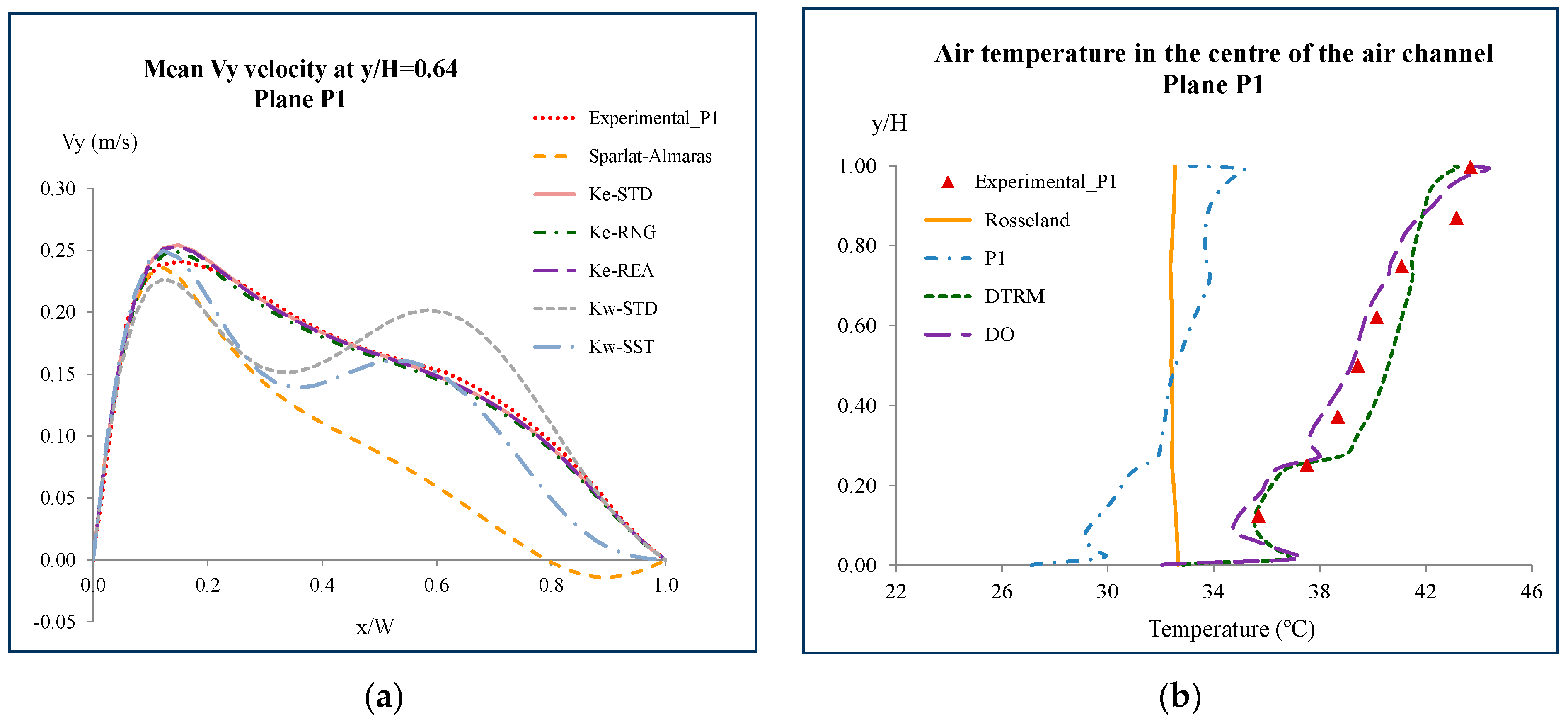
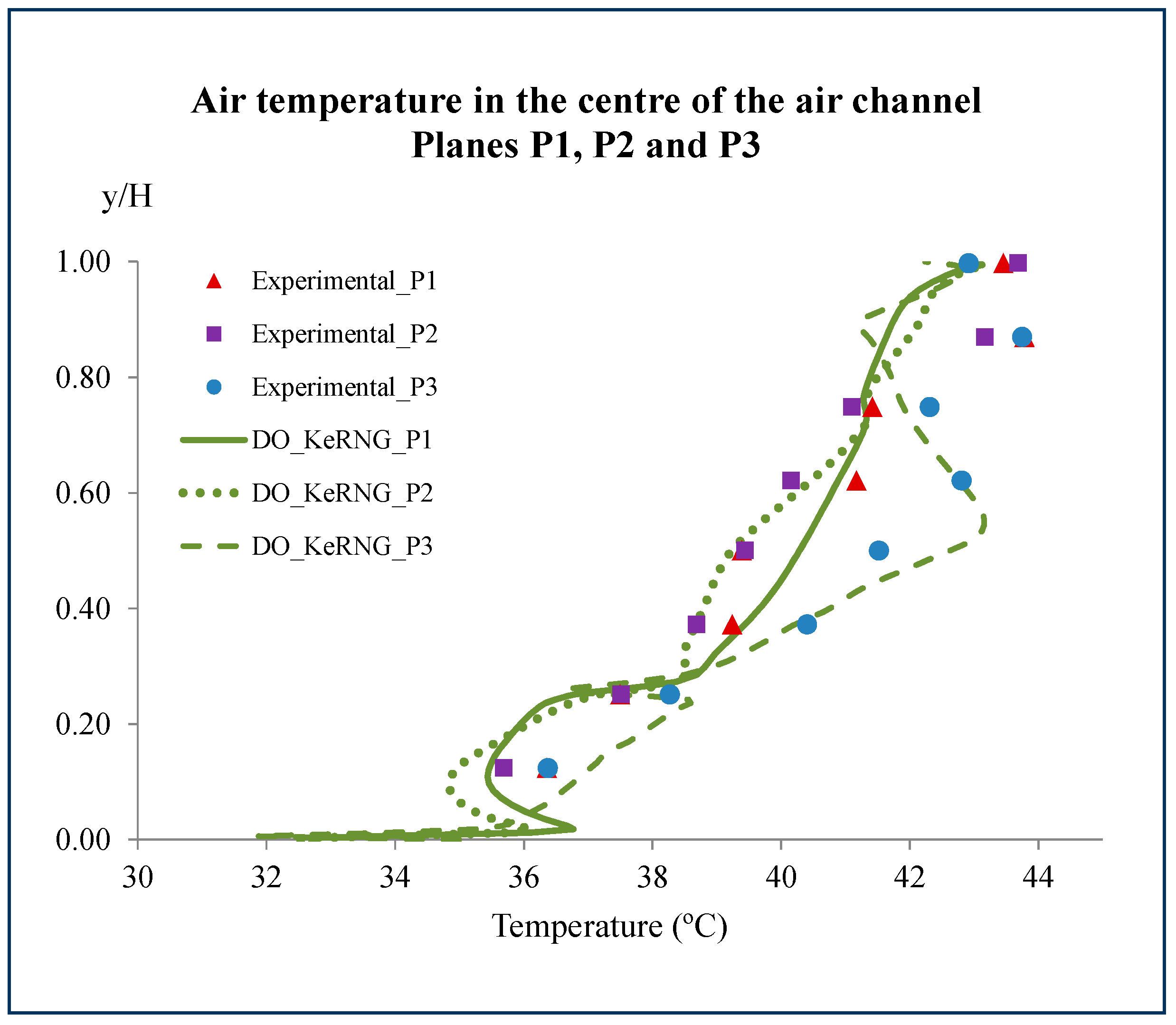
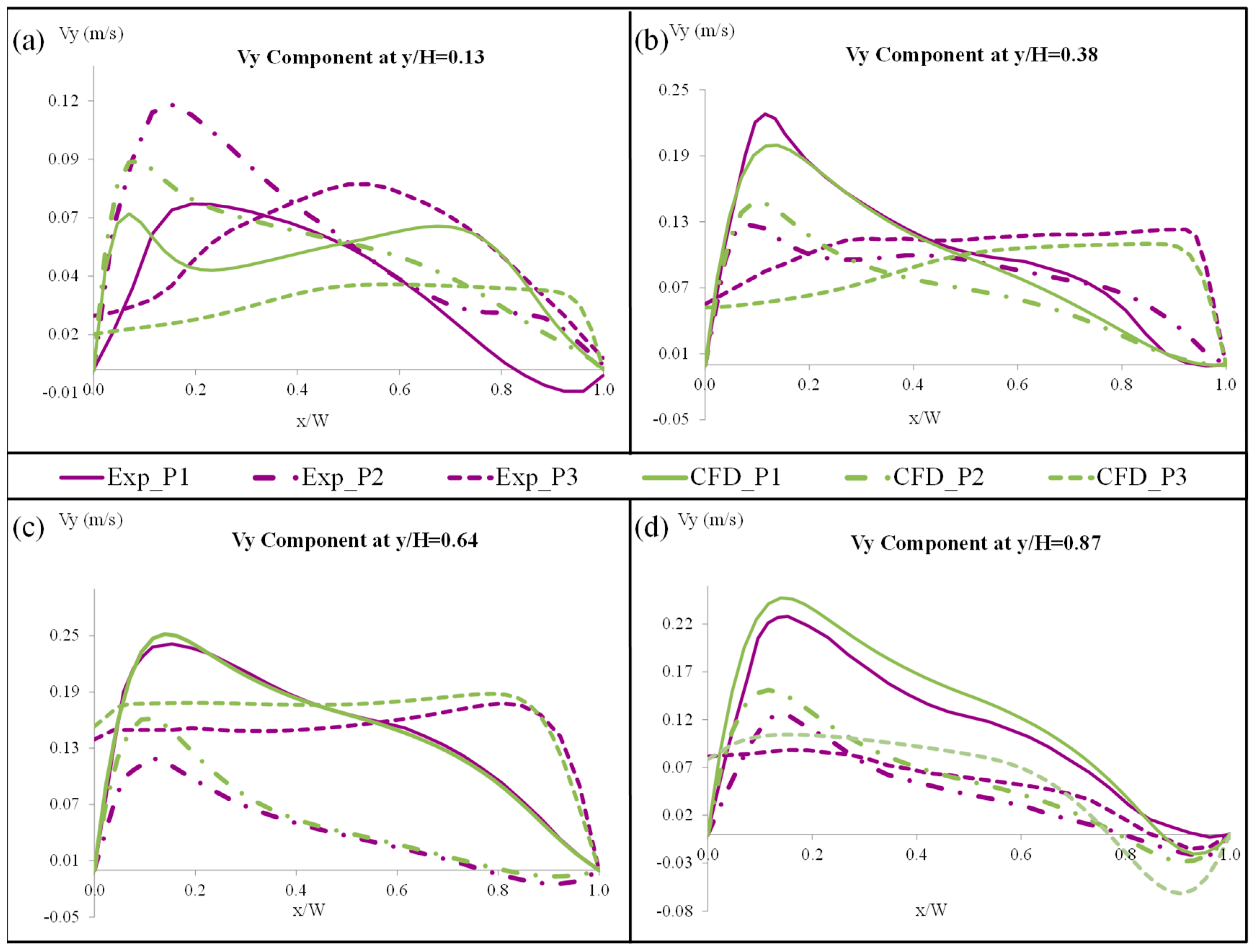
  • Experimental and numerical data have been compared in three vertical planes of the cavity perpendicular to the panels. As a result, the DO radiation model and k-ε RNG turbulence model have been selected to numerically simulate the OJVFs performance due to the low discrepancies between experimental and numerical temperature and velocity data.
  • Similar velocity and temperature trends along the whole height are repeated in OJVFs regardless of their experimental or simulated origin. Slight differences have been found in the behaviour of the air inside the cavity. In both cases, a complex, three-dimensional ventilation airflow is induced by natural convection. In conclusion, the open joints allow an effective ventilation flow in the cavity, reducing the heat transfer.

Author Contributions

Experimental Test Bench, M.N.S., S.S.; numerical simulation, M.N.S., E.G. and M.J.S.; validation and formal analysis, M.N.S., E.G., S.S., and M.J.S.; writing—original draft preparation, M.N.S., E.G., E.B., S.S. and M.J.S.; writing—review and editing E.G., E.B. and M.J.S.; supervision, E.B., M.J.S. All authors have read and agreed to the published version of the manuscript.

Funding

This research was funded by the Spanish Ministry of Science and Innovation and co-financed by FEDER funds, under REHABILITAGEOSOL (RTC-2016-5004-3) and SISGENER (RTC-2017-6491-3) projects.

Acknowledgments

This research has been developed in the framework of the REHABILITAGEOSOL and SISGENER projects. Authors wish to express their gratitude for the support of IEA EBC Annex 71.

Conflicts of Interest

The authors declare no conflict of interest.

References

  1. Directive 2010/31/EU of the European Parliament and of the Council of 19 May 2010 on the Energy Performance of Buildings. Available online: https://eur-lex.europa.eu/legal-content/ES/TXT/?uri=celex%3A32010L0031 (accessed on 4 November 2019).
  2. Directive 2012/27/EU of the European Parliament and of the Council of 25 October 2012 on energy efficiency, amending Directives 2009. Available online: https://eur-lex.europa.eu/legal-content/ES/TXT/?uri=celex%3A32012L0027 (accessed on 4 November 2019).
  3. The National Energy Code of Canada for Buildings 2017 (NECB 2017). National Research Council of Canada. Canadian Commission on Building and Fire Codes. Available online: https://nrc.canada.ca/en (accessed on 4 November 2019).
  4. Building Energy Codes Program (BECP). U.S. Department of Energy (DOE). Available online: https://www.energycodes.gov/adoption (accessed on 4 November 2019).
  5. Ministry of Construction of the People’s Republic of China. China Design Standard for Energy Efficiency of Residential Buildings; JGJ 26-2010: In Severe Cold and Cold Zones; Ministry of Construction of the People’s Republic of China: Beijing, China, 2010.
  6. Oropeza-Perez, I.; Alberg Østergaard, P. Active and passive cooling methods for dwellings: A review. Renew. Sustain. Energy Rev. 2018, 82, 531–544. [Google Scholar] [CrossRef]
  7. Ascione, F.; De Masi, R.F.; de Rossi, F.; Ruggiero, S.; Vanoli, G.P. Optimization of building envelope design for nZEBs in Mediterranean climate: Performance analysis of residential case study. Appl. Energy 2016, 183, 938–957. [Google Scholar] [CrossRef]
  8. Soutullo, S.; Sánchez, M.N.; Enríquez, R.; Olmedo, R.; Jiménez, M.J. Bioclimatic vs conventional building: Experimental quantification of the thermal improvements. Energy Procedia 2017, 122, 823–828. [Google Scholar] [CrossRef]
  9. Berardi, U.; Bisegna, F.; Santoli, L.; Evangelisti, L.; Ferreira, P.; Gori, P.; Guattari, C.; Klingenberg, K.; Mattoni, B.; Wright, G.S. From Efficient to Sustainable and Zero Energy Consumption Buildings. In Handbook of Energy Efficiency in Buildings: A Life Cycle Approach; Asdrubali, F., Desideri, U., Eds.; Butterworth-Heinemann: Oxford, UK, 2019; Chapter 3; pp. 75–205. [Google Scholar]
  10. Kosutovaa, K.; van Hooffa, T.; Vanderwel, C.; Blockena, B.; Hensen, J. Cross-ventilation in a generic isolated building equipped with louvers: Wind-tunnel experiments and CFD simulations. Build. Environ. 2019, 154, 263–280. [Google Scholar] [CrossRef]
  11. Saadatian, O.; Sopian, K.; Lim, C.H.; Asim, N.; Sulaiman, M.Y. Trombe walls: A review of opportunities and challenges in research and development. Renew. Sustain. Energy Rev. 2012, 16, 6340–6351. [Google Scholar] [CrossRef]
  12. Pergolini, M.; Ulpiani, G.; Shehi, O.; Di Perna, C.; Stazi, F. Controlled inlet airflow in ventilated facades: A numerical analysis. In Proceedings of the 10th International Conference IAQVEC 2019: Indoor Air Quality, Ventilation and Energy Conservation in Buildings, Bari, Italy, 5–7 September 2019; Volume 609, p. 032009. [Google Scholar]
  13. Evins, R. A review of computational optimization methods applied to sustainable building design. Renew. Sustain. Energy Rev. 2013, 22, 230–245. [Google Scholar] [CrossRef]
  14. Harish, V.S.K.V.; Kumar, A. A review on modelling and simulation of building energy systems. Renew. Sustain. Energy Rev. 2016, 56, 1272–1292. [Google Scholar] [CrossRef]
  15. Crawley, D.B.; Hand, J.W.; Kummert, M.; Griffith, B.T. Contrasting the capabilities of building energy performance simulation programs. Build. Environ. 2008, 43, 661–673. [Google Scholar] [CrossRef] [Green Version]
  16. Ramponi, R.; Blocken, B. CFD simulation of cross-ventilation flow for different isolated building configurations: Validation with wind tunnel measurements and analysis of physical and numerical diffusion effects. J. Wind Eng. Ind. Aerodyn. 2012, 104, 408–418. [Google Scholar] [CrossRef]
  17. Suárez, M.J.; Gutiérrez, A.J.; Parrondo, J.L.; Blanco, E. Analysis of an Attached Sunspace with a Thermal Inertia Floor. Energies 2018, 11, 1136. [Google Scholar] [CrossRef] [Green Version]
  18. Jomehzadeh, F.; Nejat, P.; Calautit, J.K.; Yusof, M.B.M.; Zaki, S.A.; Hughes, B.R.; Yazid, M.N.A.W.M. A review on windcatcher for passive cooling and natural ventilation in buildings, Part 1: Indoor air quality and thermal comfort assessment. Renew. Sustain. Energy Rev. 2017, 70, 736–756. [Google Scholar] [CrossRef]
  19. Wang, Y.; Shukla, A.; Liu, S. A state of art review on methodologies for heat transfer and energy flow characteristics of the active building envelopes. Renew. Sustain. Energy Rev. 2017, 78, 1102–1116. [Google Scholar] [CrossRef]
  20. Suárez, M.J.; Soutullo, S.; Navarro, A.; Blanco, E. Heat collection in an attached sunspace. Renew. Energy 2020, 145, 2144–2150. [Google Scholar] [CrossRef]
  21. Santiago, J.L.; Rivas, E.; Sanchez, B.; Buccolieri, R.; Martin, F. The Impact of Planting Trees on NOx Concentrations: The Case of the Plaza de la Cruz Neighborhood in Pamplona (Spain). Atmosphere 2017, 8, 131. [Google Scholar] [CrossRef] [Green Version]
  22. Liu, S.; Kwok, Y.T.; Lau, K.K.L.; Chan, P.W.; Ng, E. Investigating the energy saving potential of applying shading panels on opaque façades: A case study for residential buildings in Hong Kong. Energy Build. 2019, 193, 78–91. [Google Scholar] [CrossRef]
  23. Katsaprakakis, D.A.; Georgila, K.; Zidianakis, G.; Michopoulos, A.; Psarras, N.; Christakis, D.G.; Kanouras, S. Energy upgrading of buildings. A holistic approach for the natural history museum of Crete, Greece. Renew. Energy 2017, 114, 1306–1332. [Google Scholar] [CrossRef]
  24. Fantucci, S.; Serra, V. Investigating the performance of reflective insulation and low emissivity paints for the energy retrofit of roof attics. Energy Build. 2019, 182, 300–310. [Google Scholar] [CrossRef]
  25. Sanchez, E.; Rolando, A.; Sant, R.; Ayuso, L. Influence of natural ventilation due to buoyancy and heat transfer in the energy efficiency of a double skin facade building. Energy Sustain. Dev. 2016, 33, 139–148. [Google Scholar] [CrossRef] [Green Version]
  26. Ziasistani, N.; Fazelpour, F. Comparative study of DSF, PV-DSF and PV-DSF/PCM building energy performance considering multiple parameters. Sol. Energy 2019, 187, 115–128. [Google Scholar] [CrossRef]
  27. Huang, J.; Yu, J.; Yang, H. Effects of key factors on the heat insulation performance of a hollow block ventilated wall. Appl. Energy 2018, 232, 409–423. [Google Scholar] [CrossRef]
  28. Zhang, C.; Gang, W.; Xu, X.; Li, L.; Wang, J. Modelling, experimental test, and design of an active air permeable wall by utilizing the low-grade exhaust air. Appl. Energy 2019, 240, 730–743. [Google Scholar] [CrossRef]
  29. Yang, J.; Wang, J.; Xiong, F.; Liang, H.; Li, Y. Assessment of Building External Wall Thermal Performance Based on Temperature Deviation Impact Factor under Discontinuous Radiant Heating. J. Therm. Sci. 2019, 28, 1129–1140. [Google Scholar] [CrossRef]
  30. Halawa, E.; Ghaffarianhoseini, A.; Ghaffarianhoseini, A.; Trombley, J.; Hassan, N.; Baig, M.; Yusoff, S.Y.; Ismail, M.A. A review on energy conscious designs of building façades in hot and humid climates: Lessons for (and from) Kuala Lumpur and Darwin. Renew. Sustain. Energy Rev. 2018, 82, 2147–2161. [Google Scholar] [CrossRef]
  31. Bikas, D.; Tsikaloudaki, K.; Kontoleon, K.J.; Giarma, C.; Tsoka, S.; Tsirigoti, D. Ventilated Facades: Requirements and Specifications Across Europe, International Conference on Sustainable Synergies from Buildings to the Urban Scale, SBE16. Procedia Environ. Sci. 2017, 38, 148–154. [Google Scholar] [CrossRef]
  32. Barbosa, S.; Ip, K. Perspectives of double skin façades for naturally ventilated buildings: A review. Renew. Sustain. Energy Rev. 2014, 40, 1019–1029. [Google Scholar] [CrossRef]
  33. Nizovtsev, M.I.; Letushko, V.N.; Yu. Borodulin, V.; Sterlyagov, A.N. Experimental studies of the thermo and humidity state of a new building facade insulation system based on panels with ventilated channels. Energy Build. 2020, 206, 109607. [Google Scholar] [CrossRef]
  34. Kalyanova Larsen, O.; Liu, M. Computational performance prediction of Double-Skin Ventilated Facade. In Building Performance Simulation and Characterisation of Adaptive Facades—Adaptive Facade Network; Favoino, F., Loonen, R.C.G.M., Doya, M., Goia, F., Bedon, C., Babich, F., Eds.; TU Delft Open: Delft, The Netherlands, 2018; Chapter 9; pp. 89–94. [Google Scholar]
  35. Recatala, M.A.; Morales, S.G.; van den Bossche, N. Experimental assessment of rainwater management of a ventilated façade. J. Build. Phys. 2018, 42, 38–67. [Google Scholar] [CrossRef]
  36. Yang, H.; Xie, Y.; Yuan, J. Potential of self-drying siding with raised air cavities for building envelopes. Build. Environ. 2019, 152, 172–181. [Google Scholar] [CrossRef]
  37. Souza, L.C.O.; Souza, H.A.; Rodrigues, E.F. Experimental and numerical analysis of a naturally ventilated double-skin façade. Energy Build. 2018, 165, 328–339. [Google Scholar] [CrossRef]
  38. Wang, Y.; Chen, Y.; Li, C. Airflow modeling based on zonal method for natural ventilated double skin façade with Venetian blinds. Energy Build. 2019, 191, 211–223. [Google Scholar] [CrossRef]
  39. Dama, A.; Angeli, D.; Kalyanova Larsen, O. Naturally ventilated double-skin façade in modeling and experiments. Energy Build. 2017, 144, 17–29. [Google Scholar] [CrossRef] [Green Version]
  40. Zhang, T.; Yang, H. Flow and heat transfer characteristics of natural convection in vertical air channels of double-skin solar façades. Appl. Energy 2019, 242, 107–120. [Google Scholar] [CrossRef]
  41. Giancola, E.; Sánchez, M.N.; Friedrich, M.; Kalyanova Larsen, O.; Nocente, A.; Avesani, S.; Babich, F.; Goia, F. Possibilities and challenges of different experimental techniques for airflow characterisation in the air cavities of façades. J. Facade Des. Eng. 2018, 6, 34–48. [Google Scholar]
  42. Ibañez-Puy, M.; Vidaurre-Arbizu, M.; Sacristán-Fernández, J.A.; Martín-Gómez, C. Opaque ventilated façades: Thermal and energy performance review. Renew. Sustain. Energy Rev. 2017, 79, 180–191. [Google Scholar] [CrossRef]
  43. Stazi, F.; Ulpiani, G.; Pergolini, M.; Magni, D.; Perna, C.D. Experimental comparison between three types of opaque ventilated facades. Open Constr. Build. Technol. J. 2018, 12, 296–308. [Google Scholar] [CrossRef] [Green Version]
  44. Astorqui, J.S.C.; Porras-Amores, C. Ventilated Façade with double chamber and flow control device. Energy Build. 2017, 149, 471–482. [Google Scholar] [CrossRef]
  45. Diallo, T.M.O.; Zhao, X.; Dugue, A.; Bonnamy, P.; Miguel, F.J.; Martinez, A.; Theodosiou, T.; Liu, J.S.; Brown, N. Numerical investigation of the energy performance of an Opaque Ventilated Façade system employing a smart modular heat recovery unit and a latent heat thermal energy system. Appl. Energy 2017, 205, 130–152. [Google Scholar] [CrossRef]
  46. Fantucci, S.; Marinosci, C.; Serra, V.; Carbonaro, C. Thermal performance assessment of an opaque ventilated façade in the summer period: Calibration of a simulation model through in-field measurements. Energy Procedia 2017, 111, 619–628. [Google Scholar] [CrossRef] [Green Version]
  47. Peci Lopéz, F.; de Adana Santiago, M.R. Sensitivity study of an opaque ventilated facade in the winter season in different climate zones in Spain. Renew. Energy 2015, 75, 524–533. [Google Scholar] [CrossRef]
  48. Gagliano, A.; Nocera, F.; Aneli, S. Thermodynamic analysis of ventilated façades under different wind conditions in summer period. Energy Build. 2016, 122, 131–139. [Google Scholar] [CrossRef]
  49. Soutullo, S.; Sánchez, M.N.; Enríquez, R.; Jiménez, M.J.; Heras, M.R. Empirical estimation of the climatic representativeness in two different areas: Desert and Mediterranean climates. Energy Procedia 2017, 122, 829–834. [Google Scholar] [CrossRef]
  50. Agathokleous, R.A.; Kalogirou, S.A. Part I: Thermal analysis of naturally ventilated BIPV system: Experimental investigation and convective heat transfer coefficients estimation. Sol. Energy 2018, 169, 673–681. [Google Scholar] [CrossRef]
  51. Agathokleous, R.A.; Kalogirou, S.A. Part II: Thermal analysis of naturally ventilated BIPV system: Modeling and Simulation. Sol. Energy 2018, 169, 682–691. [Google Scholar] [CrossRef]
  52. Lai, C.; Hokoi, S. Experimental and numerical studies on the thermal performance of ventilated BIPV curtain walls. Indoor Built Environ. 2017, 26, 1243–1256. [Google Scholar] [CrossRef]
  53. Luo, Y.; Zhang, L.; Wang, X.; Xie, L.; Liu, Z.; Wu, J.; Zhang, Y.; He, X. A comparative study on thermal performance evaluation of a new double skin façade system integrated with photovoltaic blinds. Appl. Energy 2017, 199, 281–293. [Google Scholar] [CrossRef]
  54. Li, Y.; Darkwa, J.; Kokogiannakis, G. Heat transfer analysis of an integrated double skin façade and phase change material blind system. Build. Environ. 2017, 125, 111–121. [Google Scholar] [CrossRef]
  55. Kylili, A.; Fokaides, P.A. A High Performance Controlled Temperature Building Shell for the Sustainable Upgrading of Buildings. Procedia Environ. Sci. 2017, 38, 130–139. [Google Scholar] [CrossRef]
  56. Giancola, E.; Sanjuan, C.; Blanco, E.; Heras, M.R. Experimental assessment and modelling of the performance of an open joint ventilated façade during actual operating conditions in mediterranean climate. Energy Build. 2012, 54, 363–375. [Google Scholar] [CrossRef]
  57. Stazi, F.; Tomassoni, F.; Vegliò, A.; Di Perna, C. Experimental evaluation of ventilated walls with an external clay cladding. Renew. Energy 2011, 36, 3373–3385. [Google Scholar] [CrossRef]
  58. Blanco, J.M.; Buruaga, A.; Rojí, E.; Cuadrado, J.; Pelaz, B. Energy assessment and optimization of perforated metal sheet doubleskin facades through Design Builder; A case study in Spain. Energy Build. 2016, 111, 326–336. [Google Scholar] [CrossRef]
  59. Stazi, F.; Vegli, A.; Di Perna, C. Experimental assessment of a zinc-titanium ventilated façade in a mediterranean climate. Energy Build. 2014, 69, 525–534. [Google Scholar] [CrossRef]
  60. Fernandes-Maciel, A.C.; Carvalho, M.T. Operational energy of opaque ventilated façades in Brazil. J. Build. Eng. 2019, 25, 100775. [Google Scholar] [CrossRef]
  61. Petritchenko, M.R.; Kotov, E.V.; Nemova, D.V.; Tarasova, D.S.; Sergeev, V.V. Numerical simulation of ventilated facades under extreme climate conditions. Mag. Civ. Eng. 2018, 77, 130–140. [Google Scholar]
  62. Balter, J.; Pardal, C.; Paricio, I.; Ganem, C. Air cavity performance in opaque ventilated façades in accordance with the spanish technical building code. Arch. City Environ. 2019, 13, 211–232. [Google Scholar] [CrossRef]
  63. Loonen, R.C.G.M.; Favoino, F.; Hensen, J.L.M.; Overend, M. Review of current status, requirements and opportunities for building performance simulation of adaptive facades. J. Build. Perform. Simul. 2017, 10, 205–223. [Google Scholar] [CrossRef] [Green Version]
  64. Giancola, E. Computational performance prediction of Double-Skin Opaque Ventilated Façade. In Building Performance Simulation and Characterisation of Adaptive Facades—Adaptive Facade Network; COST Favoino, F., Loonen, R.C.G.M., Doya, M., Goia, F., Bedon, C., Babich, F., Eds.; TU Delft Open: Delft, The Netherlands, 2018; Chapter 10; pp. 90–100. [Google Scholar]
  65. Sánchez, M.N.; Giancola, E.; Suárez, M.J.; Blanco, E.; Heras, M.R. Experimental evaluation of the airflow behaviour in horizontal and vertical Open Joint Ventilated Facades using Stereo-PIV. Renew. Energy 2017, 109, 613–623. [Google Scholar] [CrossRef]
  66. Sánchez, M.N.; Sanjuan, C.; Suárez, M.J.; Heras, M.R. Experimental assessment of the performance of open joint ventilated façades with buoyancy-driven airflow. Sol. Energy 2013, 91, 131–144. [Google Scholar] [CrossRef]
  67. Sanjuan, C.; Sánchez, M.N.; Enriquez, R.; Heras, M.R. Experimental PIV Techniques Applied to the Analysis of Natural Convection in Open Joint Ventilated Facades. Energy Procedia 2012, 30, 1216–1225. [Google Scholar] [CrossRef] [Green Version]
  68. Sanjuan, C.; Sánchez, M.N.; Heras, M.R.; Blanco, E. Experimental analysis of natural convection in open joint ventilated facades with 2D PIV. Build. Environ. 2011, 46, 2314–2325. [Google Scholar] [CrossRef]
  69. Sciacchitano, A. Uncertainty quantification in particle image velocimetry. Meas. Sci. Technol. 2019, 30, 092001. [Google Scholar] [CrossRef] [Green Version]
  70. Sanjuan, C.; Suárez, M.J.; González, M.; Pistono, J.; Blanco, E. Energy performance of an open-joint ventilated façade compared with a conventional sealed cavity façade. Sol. Energy 2011, 85, 1851–1863. [Google Scholar] [CrossRef]
  71. Suárez, M.J.; Sanjuan, C.; Gutiérrez, A.J.; Pistono, J.; Blanco, E. Energy evaluation of a horizontal open joint ventilated façade. Appl. Therm. Eng. 2012, 37, 302–313. [Google Scholar] [CrossRef]
  72. Suárez, M.J.; Gutiérrez, A.J.; Pistono, J.; Blanco, E. CFD analysis of heat collection in a glazed gallery. Energy Build. 2011, 43, 108–116. [Google Scholar] [CrossRef]
  73. Coussirat, M.; Guardo, A.; Jou, E.; Egusquiza, E.; Cuerva, E.; Alavedra, P. Performance and influence of numerical sub-models on the CFD simulation of free and forced convection in double-glazed ventilated façades. Energy Build. 2008, 40, 1781–1789. [Google Scholar] [CrossRef]
  74. Gray, D.D.; Giorgini, A. The validity of the Boussinesq approximation for liquids and gases. Int. J. Heat Mass Transf. 1976, 19, 545–551. [Google Scholar] [CrossRef]
  75. Yakhot, V.V.; Orszag, S.A. Renormalization group analysis of turbulence: I. Basic theory. J. Sci. Comput. 1986, 1, 1–51. [Google Scholar] [CrossRef]
  76. Launder, B.E.; Spalding, D.B. The numerical computation of turbulent flows. Comput. Methods Appl. Mech. Eng. 1974, 3, 269–289. [Google Scholar] [CrossRef]
  77. Chen, Q. Comparison of different k-ε models for indoor airflow computations. Numer. Heat Transf. 1995, 28, 353–369. [Google Scholar] [CrossRef]
Figure 1. Experimental laboratory model: frontal view (a) and lateral view of the ventilated cavity with airflow arrows (b).
Energies 13 00146 g001
Figure 2. Experimental laser equipment for particle image velocimetry (PIV) techniques: real image (a) and Stereo-PIV schema (b).
Energies 13 00146 g002
Figure 3. Thermal monitoring: surface panel temperature sensors (a) and air temperature thermocouples location inside the cavity (b).
Energies 13 00146 g003
Figure 4. Geometry of the OJVF numerical model (upper part) and experimental laboratory test bench (lower part).
Energies 13 00146 g004
Figure 5. Boundary conditions scheme of the OJVF.
Energies 13 00146 g005
Figure 6. Mesh detail of the upper area of the OJVF.
Energies 13 00146 g006
Figure 7. Comparison of vertical velocity profiles for Ra = 1.0 × 10⁹ conditions in the P1 plane at y/H = 0.13 in the cavity.
Energies 13 00146 g007
Figure 8. Boundary layers y+ values evaluated on the inner and outer layers of the ventilated air cavity.
Energies 13 00146 g008
Figure 9. Vy velocity component for turbulence models (a) and temperature distribution inside the air cavity for radiation models (b). Ra = 1.0 × 10⁹ conditions.
Energies 13 00146 g009
Figure 10. Temperature distribution inside the air cavity at three different planes.
Energies 13 00146 g010
Figure 11. Vertical velocity component of airflow inside the ventilated cavity at different heights: (a) y/H = 0.13, (b) y/H = 0.38, (c) y/H = 0.64 and (d) y/H = 0.87.
Energies 13 00146 g011
Table 1. Structure and physical properties of the open joint ventilated facades (OJVF) laboratory model.
LayerMaterial (Wide × High)Thickness (mm)Thermal Conductivity (W/(m·K))Density (Kg/m3)Heat Capacity (J/(kg·K))
Outer Skin16 Aluminium Panels (0.3 × 0.2 m2)12352699896
Ventilated CavityAir (25 °C) (1.225 × 0.825 m2)450.025512251007
Inner SkinGlass (1.225 × 0.825 m2)50.812719871
Seeding BoxWood Boards (2.0 × 1.1 m2)190.1737002310
Table 2. Mesh discretization cases evaluated in the sensitivity analysis.
Mesh DensityTotal Number of Cells (Millions)Cavity Width DivisionsDistance from the Cell Node to the Wall (In the Width of the Cavity)
Thick Mesh0.5153 mm (uniform distance in air cavity width)
Medium Mesh0.8331 mm (near inner wall)
Fine Mesh1431.05 mm (uniform distance in air cavity width)

