Article

The ElectricalVehicle Simulator for Charging Station in Mode 3 of IEC 61851-1 Standard

1
Faculty of Electrical Engineering and Computer Science, Stefan cel Mare University of Suceava, 720229 Suceava, Romania
2
National Research and Development Institute for Cryogenic and Isotopic Technologies-ICSI, 240050 Rm. Valcea, Romania
*
Authors to whom correspondence should be addressed.
Energies 2020, 13(1), 176; https://doi.org/10.3390/en13010176
Submission received: 9 December 2019 / Revised: 22 December 2019 / Accepted: 23 December 2019 / Published: 31 December 2019
(This article belongs to the Special Issue Fuel Cell Renewable Hybrid Power Systems)

Abstract

:
As fuel consumption in the transport sector has increased at a faster pace than in other sectors, the use of electromobility represents the main strategy adopted by the automotive industry. In this context, as the number of electrical vehicles (EVs) will increase, it will also be necessary to increase the number of charging stations. The present paper presents a complete solution for charging stations that can be located in the office or mall parking area. This solution includes a mode 3 AC charging stations of International Electrotechnical Commission (IEC) 61851-1 Standard, an EV simulator for testing the good functionality of the charging stations (i.e., communications, residual-current device (RCD) protection) and a software application used for controlling the charging process by the programmable logic controller (PLC).

1. Introduction

Romania, as a signatory country of the Paris Agreement [1], has committed to reducing greenhouse gas emissions by 43% by 2030 compared to 2005 and to participate in the European Union’s efforts to reduce greenhouse gas emissions by 30% by 2030.
In Reference [2], the authors depicted that the charging time is one of the main challenges that the electrical vehicle (EV) industry is facing. Generally, the EV charging levels are classified according to their power charging rates [3]. Overnight charging takes place in level I, as the EVs are plugged to a convenient power outlet (120 V) for slow charging (1.5–2.5 kW) over long hours. The main concern of level-I is the long charging time, which renders this charging level unsuitable for long driving cycles when more than one charging operation is needed. Moreover, from the electrical grid operation point of view, the long charging hours at night overloads the distribution transformers as they are not allowed to rest in a grid system with a high number of connected EVs [4]. Level-II charging requires a 240 V outlet; thus, it is characteristically used as the prime charging means for public and private facilities. This charging level is capable of supplying power in the range of 4–6.6 kW over a period of 3–6 h in order to restock the depleted EV batteries. The time required is still the main drawback in this charging level. Additionally, voltage sags and high-power losses in an electrical grid system with a high penetration of level II charging are some of the facing challenges for its widespread. Control and coordination in level II would reduce the negative impacts of level-II charging [5]; however, this requires an extensive communication system to be adopted. In general, both levels I and II require single-phase power sources with onboard vehicle chargers. On the contrary, three-phase power systems are used with off-board chargers for level III fast charging rates (50–75 kW). The use of fast charging stations significantly reduces the EV charging time for a complete charging cycle. Additionally, widespread deployment of fast EV charging stations across the urban and the residential areas would eliminate the EV range anxiety concern [6,7]. However, the high-power charging rates are essential over a short interval of time for level-III charging which imposes a very high demand on the utility grid [8,9]. The current grid infrastructure is not capable of supporting the desired high charging rates of level-III. Thus, accomplishing fast charging rates while solely depending on the electrical grid does require not only the improvement of the charging system but also the improvement of the electrical grid capacity. Additionally, drawing large amounts of current from the electrical grid will increase the utility charges, especially at the peak hours and, consequently, will increase the system cost. The impact of an EV charging station load on the electric grid systems is thoroughly discussed in Reference [10].
Romania, according to European Commission (EC) Directives 2016/30 November 2016 [11,12,13], has as strategic objective the clean energy [14,15]. Recently, the interest in producing electrical energy by using renewable sources is growing up. As conventional power generation sources, the wind energy is now a real competitive alternative [16]. If the renewable energy is used for charging electrical vehicles (EVs), then we can consider these vehicles with zero emissions [17]. In this context, as the number of electrical vehicles (EVs) will increase, it will also be necessary to increase the number of the charging stations which will have a negative impact on the power quality of the power network (Overvoltage, Voltage Sag) [18,19,20,21,22]. But, with the increase in the number of charging stations installed, the problem will be to carry out their maintenance. In this paper, a proposed EV simulator and a complete solution for charging stations (also called EVSE—electric vehicle supply equipment), that can be located in the office or mall parking area, are presented. The EV simulator can be a useful tool for those who do maintenance at the charging stations, as it can simulate all the cases in which an EV can be found, thus verifying the good functioning of the EVSE. The solution proposed in this paper can be implemented in the office or mall parking area, where the customers have the benefit of being able to charge their EVs for free. It is necessary to implement an efficient solution by which the customers are offered the certainty that their EV will not be disconnected from the charging station by an unauthorized person.
The originality of this paper is based on the specialized literature according to State of The Art, the originality of the research presented in the article consists in the development of an EV simulator for charging stations in mode 3, which helps the companies dedicated to the maintenance of the charging stations [22,23,24]. The innovation is given by the fact that the programmable logic controller (PLC) and human-machine interface (HMI) charging station control solution allows users to load EVs without the need for an radio-frequency identification (RFID) card, using a unique user-selected code that provides security during charging.
The unidirectional communication is achieved using the PWM (Pulse Width Modulation) signal with 1 KHz values [25,26]. The duty cycle of the PWM signal is closely related to the consumption of predefined current, which should not be exceeded. By modelling the PWM signal, the maximum current consumed by the EV can become restricted [17,18,19]. Knowing the number of phases used, the maximum permissible power can be calculated. Thus, using the PWM signal the load power can be controlled.
In the European Union and other countries that accept the standard International Electrotechnical Commission (IEC) 61851-1, it is used for charging stations. The standard is intended for defining general requirements for charging stations [20,21,22], used together with other standards (Ex. IEC 61851-22). The purpose of IEC 61851-1 is to cover EV charging equipment by providing AC power. This standard defines the input voltage limit at 1000 V.
This research tries to present a series of optimal solutions regarding the use and maintenance of charging stations. The present research represents an intermediate phase that is part of a complex research project [13]. The main objectives are the implementation of advanced theoretical and technological solutions to ensure some charging stations, fixed and mobile, for electric vehicles (EV) and hybrid electric vehicles plug-in (PHEV). In this context, this work represents a starting point for the development of fixed charging station in mode 3, according IEC 61851-1 Standard [24,25,26].

2. IEC 61851-1 Standard

The IEC 61851-1 is an international standard where the general requirements for EVs conductive charging systems are presented.

2.1. EV Charging Modes Defined in IEC 61851-1 Standard

According to IEC 61851-1 standard, the charging of electrical vehicles can be done in four ways (illustrated in Figure 1), as following:
  • Mode 1 is the simplest solution for charging EV. In this case the EV is connected to the residences standard socket outlets but must have a circuit breaker for overload and earth leakage protections. In this mode the charging is realized without communication and it is rated up to 16 A.
  • Mode 2 where the EV is connected to the domestic power grid via a particular cable with in-cable or in-plug control pilot and a protection device. The current must not exceed 32 A.
  • Mode 3 where the EV is connected via specific socket on a dedicated charging station that has permanently installed the control and the protection functions. The rated charging current is up to 3 × 63 A.
  • Mode 4, where the EV is fast charging in direct current (DC).

2.2. Charging Station in Mode 3 According to IEC 61851-1 Standard

For charging EV in AC, the most used solution is mode 3 because it fully guarantees the safety of people. The station has a charging controller that, via a control pilot, can communicate with vehicle and checks (before starting charging process) the following:
  • If the EV is correctly connected to the station;
  • The maximum current capability of the cable assembly coded by a resistor. If the current is higher than this value, then the electric vehicle supply equipment (EVSE) interrupts the current supply. Most EVs are equipped with two cables one for slow charge (Mode 1) and other for fast charge (Mode 3);
  • If the earthing system of the vehicle is connected correctly to EVSE.
The communication signal sent by the charging station to the EV on the control pilot and earth has a square wave shape of 1 kHz frequency and ±12.0–±0.4 V voltage range. The typically control pilot circuit according to IEC61851-1 is illustrated in Figure 2. The stage of charging cycle is identified by the station charger controller through positive voltage level of communication signal level, as follow:
  • Vehicle unconnected, when the positive level of communication signal is 12 V;
  • The cable assembly is plugged into both the EV and the EVSE, where the positive voltage level is 9 V;
  • Vehicle is ready to receive energy, when S2 (Figure 2) is closed by the vehicle and the positive voltage level is 6 V.
The EVSE can send information through the duty cycle of the communication signal to the EV about the maximum current supported by the cable used. Consequently, the EV battery management system interprets the Control Pilot signal to limit charge rate.

3. Experimental Arrangement

The proposed solution for the EV simulator, which permits simulation of a real electrical vehicle and a prototype of charging station in mode 3 according to IEC 61851-1 standard are presented in Figure 3. The experimental arrangement for these tests is illustrated in Figure 3a and the circuit diagram for charging station controlled by PLC is illustrated in Figure 3b. The dimensions of our Charging Station are 58 cm/28 cm/21 cm (L × W × H), the mass is 8 Kg and the power is 24 kW.
Because most public charging stations are equipped with a type 2 socket, the EV simulator is equipped with a specific charging EVs cable with type 2 connector. This makes it possible for the simulator to be connected to any station which is equipped with socket type 2. All stages of EV charging process from a station can be created using the proposed EV simulator. In addition, for employee-owned electric vehicles customers’ safety, the good working of station RCD protection has been implemented. To implement a complete solution for a charging station that can be placed in a mall or office parking, the authors choose the HMI-PLC system for station control. The EV Simulator is illustrated in Figure 3c.

4. Experimental Results

On the control pilot, the EVSE generates a 1 kHz square wave at ±12 volts in order to detect whether the EV is correctly plugged, to communicate the maximum power allowed by the cable and for charging begin/end process control initiated by the EV (see Figure 4a) or initiated by EVSE (see Figure 4b).
All charging stages can be generated by EVSE through the status of switch S1 (presented in Figure 2) and by EV simulator through the status of switches S2, S3 (presented in Figure 3c). These charging stages are detailed in Table 1.
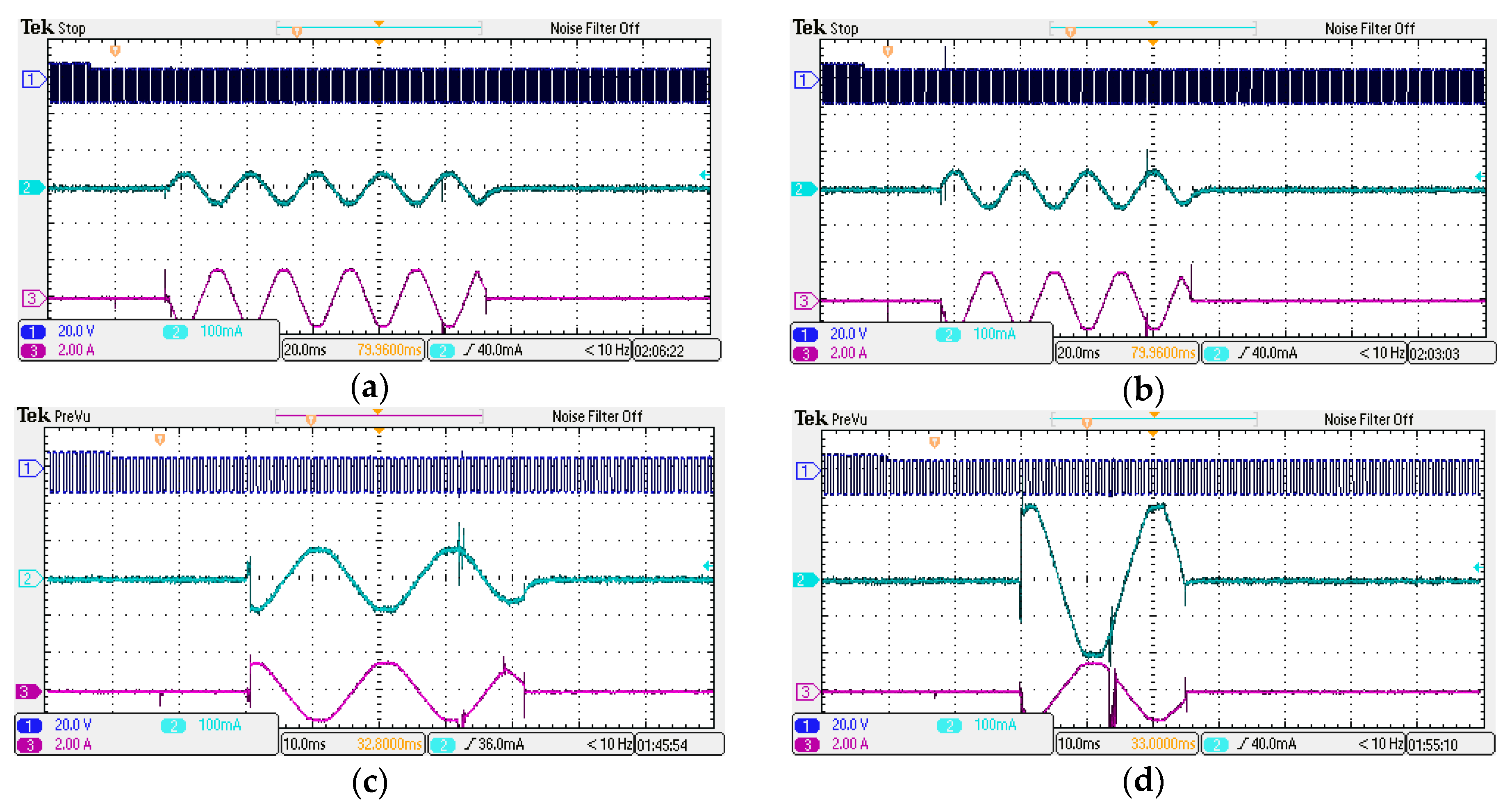
Because the people safety in stations is very important, an RCD (residual current device) has been mounted. Of course, it must be periodically tested for the proper functionality of protection by the maintenance employer. The RCD protection of the EVSE is very easy to be tested using an EV simulator and the switches S4–S8 (see Figure 3c). The experimental results at different values of residual current are presented in Figure 5 and it is shown how the RCD tripping time is reduced as the residual current increases.
The charging stations can be installed in the office or mall parking area, where the customers have the benefit of being able to charge their EVs for free. The solution must offer customers the certainty that their EV will not be disconnected from the charging station by an unauthorized person. Usually, the customers must have an RFID card that will be used to control the beginning and the end of the charging processes. The proposed solution offers the same facility to the customers without any RFID card. To test the solution proposed by the authors for the charging station, a PLC has been used to control the implemented prototype. A friendly HMI connected with PLC has been implemented in order to be easily used by the customers. For example, when a customer plugs his EV in the charging station, he should wait the confirmation on HMI and, after that, he must introduce an identification code and press the START button. In this moment the locking system of the station socket will block the charging cable connector in the station socket, preventing the unauthorized disconnection of the EV from the charging station. This type of application can be simple extended for more than one station, all controlled by the same PLC and HMI. These stations can be in the office or mall parking area. Before starting the charging command, the user must choose in HMI the number of station and a unique identification code. When the user wants to command the end of charging, he must choose the number of station and to input the identification code. After the PLC recognizes the code, the charging process is interrupted and the cable connector is unlocked. So, the features of the PLC software are as follows:
  • The user can control the charging station via an easy HDMI interface;
  • All parameters from a three-phase energy meter device (model EEM-350-D-MCB from Phoenix Contact) through MODBUS protocol using RS485 interfaces can be read;
  • An identification code is used to recognize the authorized person which commands the starting and finishing of the charging process.
The programmable logic controller (PLC) type S7-1200 and a human-machine interface (HMI) type TP700 Comfort, both from Siemens, have been used but other types of PLC or HMI can be used in order to implement the proposed solution as well. A sequence of program (realized in the dedicated software Totally Integrated Automation Portal—TIA Portal, from Siemens) and the HMI screen are presented in Figure 6a,b: The sequence from the main program, presented in Figure 6a, confirms the communication between PLC and three phase energy meter device.
This research helps the developers of Charging Station as [23,24,25]:
  • This simulation is used to realize the periodic maintenance of Charging Station, from exploitation of the RCD relay;
  • Verifying a correct functioning of the station controller;
  • The solution for controlling the Charging Stations with PLC and HMI offers users the possibility to charge the EV without an RFID card, using a unique identification code chosen by driver [26].

5. Conclusions

An EV can be charged from an EVSE only if communication between these is established and both send a confirmation that they are ready for the charging process. Periodically all charging stations must verify the good functioning by the maintenance persons. In this paper, an EV simulator has been developed that is a useful tool for those who do maintenance at the charging stations. This equipment is capable as follows:
  • To create all charging stages for an EV to a charging station in mode 3 (EVSE) according to IEC 61851-1 standard and checks if the charging station works correctly;
  • Permits measuring the charging station tripping time by generating different values of residual current.
The authors also propose a solution that can be implemented in the office or mall parking area, where the customers have the benefit of being able to charge their EVs for free. The charging stations are controlled by a PLC-HMI system and the customers are offered the certainty that their EV will not be disconnected from the charging station by an unauthorized person. When a customer plugged his EV to the charging station before START charging, it is necessary to introduce an identification code in HMI. For STOP charging, unlock the cable connector and disconnect the EV from the charging station; the PLC checks whether it introduced the same unique identification code in order to validate these actions.

Author Contributions

Conceptualization, M.R.; methodology, M.R. and G.R.; validation, C.F., M.S.R. and C.A.; formal analysis, M.R.; investigation, M.S.R. and G.R.; data curation, G.R.; writing—original draft preparation, A.-R.F., M.S.R. and M.R.; writing—review and editing, M.R. and C.F.; visualization, A.-R.F.; supervision, C.A.; project administration, A.-R.F. and C.F. All authors have read and agreed to the published version of the manuscript.

Acknowledgments

This work was supported by a grant from the Romanian Ministry of Research and Innovation, CCCDI-UEFISCDI, project number PN-III-P1-1.2-PCCDI-2017-0776/No. 36 PCCDI/15.03.2018, within PNCDI III.

Conflicts of Interest

The authors declare no conflict of interest.

References

  1. United Nations Framework Convention on Climate Change (UNFCCC), Paris Agreement. Available online: https://unfccc.int/process-and-meetings/the-paris-agreement/the-paris-agreement (accessed on 28 August 2019).
  2. Hidrue, M.K.; Parsons, G.R.; Kempton, W.; Gardner, M.P. Willingness to pay for electric vehicles and their attributes. Resour. Energy Econ. 2011, 33, 686–705. [Google Scholar] [CrossRef] [Green Version]
  3. Yilmaz, M.; Krein, P.T. Review of battery charger topologies, charging power levels and infrastructure for plug-in electric and hybrid vehicles. IEEE Trans. Power Electron. 2013, 28, 2151–2169. [Google Scholar] [CrossRef]
  4. Fairley, P. Speed bumps ahead for electric-vehicle charging. IEEE Spectr. 2010, 47, 13–14. [Google Scholar] [CrossRef]
  5. Clement-Nyns, K.; Haesen, E.; Driesen, J. The impact of Charging plug-in hybrid electric vehicles on a residential distribution grid. IEEE Trans. Power Syst. 2010, 25, 371–380. [Google Scholar] [CrossRef] [Green Version]
  6. Yunus, K.; la Parra, H.Z.D.; Reza, M. Distribution Grid Impact of Plug-In Electric Vehicles Charging at Fast Charging Stations Using Stochastic Charging Model. In Proceedings of the 2011 14th European Conference on Power Electronics and Applications, Birmingham, UK, 30 August–1 September 2011; pp. 1–11. [Google Scholar]
  7. Botsford, C.; Szczepanek, A. Fast Charging vs. Slow Charging: Pros and cons for the New Age of Electric Vehicles. In Proceedings of the EVS24 International Battery, Hybrid and Fuel Cell Electric Vehicle Symposium, Stavanger, Norway, 13–16 May 2009. [Google Scholar]
  8. Gnann, T.; Funke, S.; Jakobsson, N.; Plotz, P.; Sprei, F.; Bennehag, A. Fast charging infrastructure for electric vehicles: Today’s situation and future needs. Transp. Res. Part D Transp. Environ. 2018, 62, 314–329. [Google Scholar] [CrossRef]
  9. Morrow, K.; Karner, D.; Francfort, J. Plug-in Hybrid Electric Vehicle Charging Infrastructure Review (U. S. Department of Energy Vehicle Technologies Program—Advanced Vehicle Testing Activity); Idaho National Laboratory (INL): Idaho Falls, ID, USA, 2008. [Google Scholar]
  10. Deb, S.; Tammi, K.; Kalita, K.; Mahanta, P. Review of recent trends in charging infrastructure planning for electric vehicles. Wiley Interdiscip. Rev. Energy Environ. 2018, 7, e306. [Google Scholar] [CrossRef] [Green Version]
  11. Răboacă, M.S.; Badea, G.; Enache, A.; Filote, C.; Răsoi, G.; Rata, M.; Lavric, A.; Felseghi, R.-A. Concentrating Solar Power Technologies. Energies 2019, 12, 1048. [Google Scholar] [CrossRef] [Green Version]
  12. Badea, G.; Felseghi, R.-A.; Varlam, M.; Filote, C.; Culcer, M.; Iliescu, M.; Răboacă, M.S. Design and Simulation of Romanian Solar Energy Charging Station for Electric Vehicles. Energies 2019, 12, 74. [Google Scholar] [CrossRef] [Green Version]
  13. Şişman, G.R.; Oproescu, M. Predictive maintenance of power industrial electronic equipment. J. Electr. Eng. Electron. Control Comput. Sci. 2015, 1, 21–30. Available online: https://jeeeccs.net/index.php/journal/article/view/18/10 (accessed on 1 December 2019).
  14. Ahn, N.; Jo, S.Y.; Kang, S.-J. Constraint-Aware Electricity Consumption Estimation for Prevention of Overload by Electric Vehicle Charging Station. Energies 2019, 12, 1000. [Google Scholar] [CrossRef] [Green Version]
  15. Chiper, A.M. The conception and execution of a simulation workbench for an automotive fuel gauge system. J. Electr. Eng. Electron. Control Comput. Sci. 2015, 1, 15–20. Available online: https://jeeeccs.net/index.php/journal/article/view/10/3 (accessed on 1 December 2019).
  16. Bizon, N.; Thounthong, P. Real-time strategies to optimize the fueling of the fuel cell hybrid power source: A review of issues, challenges and a new approach. Renew. Sust. Energy Rev. 2018, 91, 1089–1102. [Google Scholar] [CrossRef]
  17. Beleiu, H.G.; Beleiu, I.N.; Pavel, S.G.; Darab, C.P. Management of Power Quality Issues from an Economic Point of View. Sustainability 2018, 10, 2326. [Google Scholar] [CrossRef] [Green Version]
  18. Maier, V.; Pavel, S.G.; Beleiu, H.G.; Farcas, V. Additional Indicators for Short Time Overvoltages and Voltage Impulses. In Proceedings of the 2016 International Conference and Exposition on Electrical and Power Engineering (EPE), Iasi, Romania, 20–22 October 2016; pp. 827–831. [Google Scholar] [CrossRef]
  19. Rai, K.; Jandhyala, A.; Rai, S.C. Power Intelligence and Asset Monitoring for System. J. Electr. Eng. Electron. Control Comput. Sci. 2015, 1, 31–36. Available online: https://jeeeccs.net/index.php/journal/article/view/129/106 (accessed on 1 December 2019).
  20. Maier, V.; Pavel, S.G.; Beleiu, H.G.; Buda, C. Survey Regarding Additional Indicators for Voltage Sags. In Proceedings of the 2016 International Conference on Development and Application Systems (DAS), Suceava, Romania, 19–21 May 2016; pp. 103–107. [Google Scholar] [CrossRef]
  21. Liu, G.; Kang, L.; Luan, Z.; Qiu, J.; Zheng, F. Charging Station and Power Network Planning for Integrated Electric Vehicles (EVs). Energies 2019, 12, 2595. [Google Scholar] [CrossRef] [Green Version]
  22. Bizon, N.; Thounthong, P. Fuel economy using the global optimization of the Fuel Cell Hybrid Power Systems. Energy Convers. Manag. 2018, 173, 665–678. [Google Scholar] [CrossRef]
  23. Birleanu, F.G.; Bizon, N. Principles, Architectures and Challenges for Ensuring the Integrity, Internal Control and Security of Embedded Systems. J. Electr. Eng. Electron. Control Comput. Sci. 2015, 1, 37–45. Available online: https://jeeeccs.net/index.php/journal/article/view/68/60 (accessed on 1 December 2019).
  24. Deb, S.; Tammi, K.; Kalita, K.; Mahanta, P. Impact of Electric Vehicle Charging Station Load on Distribution Network. Energies 2018, 11, 178. [Google Scholar] [CrossRef] [Green Version]
  25. UEFISCDI. Project Number PN-III-P1-1.2-PCCDI-2017-0776/No. 36 PCCDI/15.03.2018, within PNCDI III, Grant from the Romanian Ministry of Research and Innovation, CCCDI. Available online: www.smile-ev.usv.ro (accessed on 28 August 2019).
  26. Shareef, H.; Islam, M.M.; Mohamed, A. A review of the stage-of-the-art charging technologies, placement methodologies and impacts of electric vehicles. Renew. Sustain. Energy Rev. 2016, 64, 403–420. [Google Scholar] [CrossRef]
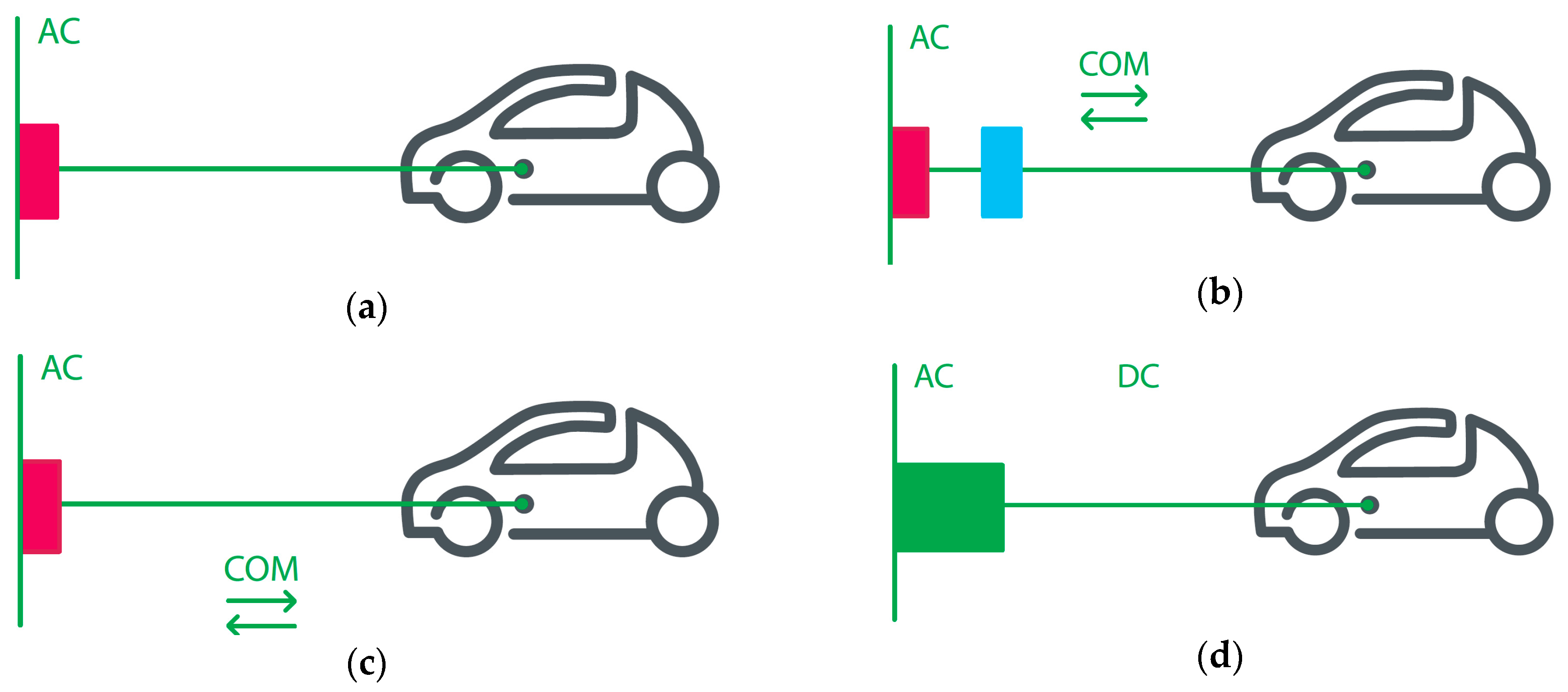
Figure 1. Different charging methods defined in IEC 61851-1: (a) Mode 1; (b) Mode 2; (c) Mode 3; (d) Mode 4.
Energies 13 00176 g001
Figure 2. Typical control pilot circuit according to IEC61851-1.
Energies 13 00176 g002
Figure 3. Experimental arrangement: (a) Experimental setup; (b) electric vehicle supply equipment (EVSE) Circuit block diagram; (c) electrical vehicle (EV) Simulator.
Energies 13 00176 g003
Figure 4. Communication signals between EVSE and EV. Ch 1 – uCP and Ch 2 – iL1 (a) Control from EV; (b) Control from EVSE.
Energies 13 00176 g004
Figure 5. Residual current device (RCD) experimental tests; Ch 1 – uCP, Ch 2 – iRCD, Ch 3 – iL1: (a) iRCD = 30 mA; (b) iRCD = 35 mA; (c) iRCD = 60 mA; (d) iRCD = 150 mA.
Energies 13 00176 g005
Figure 6. Software application: (a) programmable logic controller (PLC) software; (b) human-machine interface (HMI) screen.
Energies 13 00176 g006
Table 1. EV charging stages.
StageSwitchesDescription of the Stage
S1 (Figure 2)S2 (Figure 2 and Figure 3)S3 (Figure 3)
Figure 4a. Charging begin/end regime controlled by the electrical vehicle
AOFFOFFOFFThe vehicle is unconnected and the voltage measured by EVSE on pilot contact is +12 V DC
BOFFOFFONEVSE is not ready. In this case the cable assemble is connected to EV and to the EVSE and the voltage measured by EVSE is +9 V DC.
CON OFFONEVSE is ready and at pilot contact is generated PWM signal (+9 V– −12 V).
DONONONThe vehicle is ready and charging process is active. In this case the positive voltage level of PWM signal is depending of R3 resistor value. If ventilation in charging area is not required, the R3 = 1.3 kΩ and the positive voltage value of PWM signal is 6 V (case illustrated in Figure 4a). If in the charging area the ventilation is required, the R3 = 270 Ω the positive voltage value of PWM signal is 3 V.
EOFFONONThe vehicle is not ready and charging process is aborted.
FOFFOFFONEVSE is not ready.
GOFFOFFOFFThe vehicle is unconnected.
Figure 4b. Charging begin/end regime controlled by the station (EVSE)
AOFFOFFOFFThe vehicle is unconnected and the voltage measured by EVSE on pilot contact is +12 V DC
BOFFOFFONEVSE is not ready. In this case the cable assemble is connected to EV and to the EVSE and the voltage measured by EVSE is +9 V DC.
COFFON ONThe vehicle is ready and at pilot contact is measured 6 V DC.
DONONONThe EVSE is ready and charging process is active. In this case at pilot contact is generated PWM signal.
EOFFONONThe EVSE is not ready and charging process is aborted. In this case when S1 switches OFF the charging process continues for about 3 seconds
FOFFOFFONEV is not ready.
GOFFOFFOFFThe vehicle is unconnected.