Article

The Effect of Fuel Injection Location on Supersonic Hydrogen Combustion in a Cavity-Based Model Scramjet Combustor †

1
Department of Aerospace Engineering, Seoul National University, Seoul 08826, Korea
2
School of Aerospace and Mechanical Engineering, University of New South Wales, Australian Defence Force Academy, Canberra, ACT 2600, Australia
3
Department of Aerospace Engineering & Institute of Advanced Aerospace Technology, Seoul National University, Seoul 08826, Korea
4
Department of Physics, Faculty of Science, The Australian National University, Canberra, ACT 0200, Australia
*
Author to whom correspondence should be addressed.
This paper is an extended version of our paper presented as AIAA Technical Paper 2008-4576: “Eunju Jeong, Sean O’Byrne, In-Seuck Jeung, A. F. P. Houwing. Supersonic Combustion of Hydrogen Fuel Injection Locations in a Cavity-Based Combustor” at 44th AIAA/ASME/SAE/ASEE Joint Propulsion Conference & Exhibit., July 2008.
Energies 2020, 13(1), 193; https://doi.org/10.3390/en13010193
Submission received: 14 November 2019 / Revised: 21 December 2019 / Accepted: 26 December 2019 / Published: 1 January 2020
(This article belongs to the Special Issue Scramjet and Ramjet Combustion)

Abstract

:
Supersonic combustion experiments were performed using three different hydrogen fuel-injection configurations in a cavity-based model scramjet combustor with various global fuel–air equivalence ratios. The configurations tested were angled injection at 15° to the flow direction upstream of the cavity, parallel injection from the front step, and upstream injection from the rear ramp. Planar laser-induced fluorescence of the hydroxyl radical and time-resolved pressure measurements were used to investigate the flow characteristics. Angled injection generated a weak bow shock in front of the injector and recirculation zone to maintain the combustion as the equivalence ratio increased. Parallel and upstream injections both showed similar flame structure over the cavity at low equivalence ratio. Upstream injection enhanced the fuel diffusion and enabled ignition with a shorter delay length than with parallel injection. The presence of a flame near the cavity was determined while varying the fuel injection location, the equivalence ratio, and total enthalpy of the air flow. The flame characteristics agreed with the correlation plot for the stable flame limit of non-premixed conditions. The pressure increase in the cavity for reacting flow compared to non-reacting flow was almost identical for all three configurations. More than 300 mm downstream of the duct entrance, averaged pressure ratios at low global equivalence ratio were similar for all three injection configurations.

1. Introduction

Scramjet engines are certainly an attractive propulsion system for next-generation, high-speed aircraft. However, there still remain problems to solve such as maximizing the fuel–air mixing and understanding how best to control the supersonic combustion process. Because the time available for fuel injection, fuel-air mixing, ignition, and combustion is very short, of the order of 1 ms, researchers have developed various combustor geometries and fuel injector configurations to help solve these problems, as described below.
The simplest method used to facilitate fuel–air mixing and combustion in the scramjet engine is via transverse injection in the duct. As the fuel jet interacts with the supersonic crossflow, a bow shock is generated and fuel–air mixing, ignition, and combustion occur in the separation region. In addition, the wake region downstream of the barrel shock enhances fuel–air mixing. However, this injection method generates stagnation pressure losses due to the strong bow shock generated by the transverse jet [1,2,3,4,5]. Use of a backward-facing step immediately downstream of injection produces a high-temperature recirculation zone behind the step, and this zone can act as a continuous ignition source within the combustor. However, flame holding using a step has the disadvantage of increased drag due to the low base pressure behind the step. Parallel injection from the front wall of the step reduces the base drag, but limits the fuel–air mixing to diffusion along the mixing layer, which tends to be very gradual [6,7,8,9]. More recently, ramp injection methods, or hypermixers, have been used to generate streamwise vorticity for mixing two different gases, and these methods can minimize the stagnation pressure losses while enhancing the mixing rate [10,11,12,13,14,15,16].
Recently, fuel–air mixing and combustion studies using cavities have shown that a cavity located within the combustor is good for maintaining the flame and for enhancing fuel–air mixing by means of oscillation of characteristics within the cavity. Further studies investigating the optimal location of fuel injection around the cavity have also been undertaken. Angled injection before the cavity reduces the stagnation pressure losses compared with normal injection and contains the flame in the cavity [17,18]. In flows at Mach 2 combustor entrance conditions, upstream injection inside the cavity shows a uniform fuel/air distribution within the cavity, a wide range of fuel flow rates over which cavity combustion can be sustained, and relative insensitivity to flowfield changes that occur during the ignition event [18,19]. However, in Mach 4 combustor entrance flows, the flame is generated along the shear layer above the cavity rather than inside the cavity [20,21]. Also, cavity-based flame holders with various flush-wall fuel injection schemes can considerably influence flame structure, thermoacoustic instability, as well as mixing efficiency [22,23,24]. However, the most effective location for fuel injection is not yet known, and there are limited results for combustion in conditions where the combustor entrance Mach number is greater than 2. Recently, experiments have been performed on supersonic cavity combustion with hydrogen and ethylene fuel where the combustor inflow was Mach 4.20 [21]. Also, Jeong et al. [25] investigated the supersonic combustion phenomena for an angled fuel injection configuration according to the variation of equivalence ratios and combustor inflow conditions, using the same experimental facility and test model as used in [20,21]. As this paper is an extension of these previous studies, the focus here is on experimentally studying the influence of three different fuel injection locations: angled injection upstream of the cavity, parallel injection from the front face of the cavity, and upstream injection from the rear face of the cavity, at Mach 4 combustor inlet flow conditions.

2. Experimental Arrangement

2.1. Cavity-Based Model Scramjet Combustor

The cavity-based model scramjet combustor used in this paper consisted of a 500 mm-long rectangular duct with a constant cross-section of 52 × 25 mm, as shown in Figure 1. The inlet of the model scramjet combustor was located at the exit of the facility’s Mach 4 contoured nozzle. The cavity was installed on the bottom wall inside the combustor, 152.5 mm downstream of the inlet. It was 5 mm deep and had a 22.5° rear ramp angle. The length-to-depth ratio of this cavity was 4.8, which qualified it as an open cavity [4]. The length was defined as the distance from the cavity’s leading edge to the midpoint of the angled rear ramp wall.
Contrary to the situation for pre-mixed flames, the location of the fuel injector is vitally important to ensuring both efficient combustion and flameholding in non-premixed flames [26]. To investigate supersonic combustion according to the fuel-injection location, each of the three different fuel injector configurations shown in Figure 1 were tested separately; these are denoted in the paper as angled injection, parallel injection, and upstream injection. Angled injectors were located 20 mm upstream of the cavity front step and inclined at 15° to the horizontal. Parallel injectors were located on the cavity front step 1.5 mm above the cavity floor. Upstream direction injectors were placed on the cavity rear wall and 2.5 mm above the cavity floor. The fuel injecting direction of both parallel and upstream injection was parallel to the cavity floor. In each configuration, fuel was injected sonically from four 2 mm-diameter ports. The space between injectors was 10 mm and the space between the outermost injectors and side walls was 11 mm. A helically coiled Ludwieg tube was used for the fuel injection system, as it provided uniform hydrogen injection conditions throughout the duration of the tunnel operation. The Ludwieg tube was filled with gaseous hydrogen fuel at room temperature with an initial fuel pressure that determined the global fuel–air equivalence ratio, Φ, for the experiment.
Ultraviolet (UV) fused silica windows were installed on the top wall and on one side wall of the combustor for acquiring planar laser-induced fluorescence (PLIF) images. The laser sheet entered the top window and an intensified charge-coupled device (ICCD) camera captured the transmitted OH fluorescence signal through the side window. The hydroxyl (OH) radical was formed as an intermediate during high-temperature combustion reactions, and was used as a marker of zones where combustion was occurring [27]. The fluorescence from OH could be used to determine where ignition occurred, an important characteristic in the design of a supersonic combustor, although the fact that the OH can be relatively long-lived in these supersonic flows could confuse the determination of where within the flow the OH providing the PLIF signal might have originally been formed.
For the OH PLIF experiment, a Spectraphysics GCR4 frequency-doubled Nd:YAG laser (532 nm, 8 ns pulse) was used to pump a Spectraphysics PDL2 dye laser using a mixture of rhodamine 590 and rhodamine 610 dyes that can generate laser pulses over a range of wavelengths between 560 and 570 nm. The radiation from this dye laser was doubled in frequency using a BBO type II crystal to generate radiation between 280 and 285 nm, where A 2 Σ g + X 2 Π (1,0) rovibronic transitions could be excited. The beam was formed into a planar sheet using a combination of a cylindrical lens and spherical lens and passed through an aperture to select an illumination region having an intensity distribution whose maximum and minimum intensities varied by less than 25%. The thickness of the laser sheet was 0.32 ± 0.04 mm. This laser sheet was directed into the combustor through UV-fused silica windows at the top of the combustor model, and centered on the second injector from the side window. The edge of this sheet was located at the injection point 20 mm upstream of the injector for the angled injector case, and 5 mm upstream of the cavity leading edge for the parallel and upstream injection cases. The length of the laser sheet was approximately 60 mm. We made no attempt to obtain quantitative OH mole fraction measurements in this study, though several corrections to the raw signal were made to make the OH signal as good a qualitative indicator of OH concentration as possible. O’Byrne et al. [20] detailed the equipment used to generate and detect the PLIF signal, as well as the image corrections used to normalize the images for spatial non-uniformity in the laser sheet. The OH PLIF signal was detected using a 576 by 384-pixel Princeton Instruments ICCD camera. The intensifier gate time was set to 50 ns to filter out luminosity from the tunnel flow and chemiluminescence from combustion in the duct. A Schott WG305 filter was used in front of the camera lens to reduce the detected laser scatter and resonant fluorescence, and a UG11 filter was used to reduce the effect of broadband flow luminosity at wavelengths above the main fluorescence band at 308 nm.
A total of 16 fast-acting piezoelectric pressure transducers (Piezotronic PCB type 113 M125) were used to measure the floor static pressure during the experiment. One pressure transducer, located 70 mm downstream from the inlet leading edge on the upper surface, was used for measuring incoming flow to the combustor, whereas another pressure transducer was located within the cavity, 15 mm downstream of the cavity leading edge in the duct. A total of 14 pressure transducers were installed from 233 mm downstream of the inlet along the centerline of the duct floor at intervals of 20 mm. The first six transducer locations can be seen in Figure 1. Jeong et al. [25] detail the experimental equipment and procedures used for the pressure measurement.

2.2. Free-Piston Shock Tunnel and Flow Conditions

The experiments were performed in The Australian National University’s T3 free-piston shock tunnel, an impulse facility that is used to produce supersonic and hypersonic flows having stagnation enthalpies similar to those that would be experienced in flight. A free piston, driven by high pressure air in the reservoir tube, compressed the driver gas in the compression tube. As the piston approached the end of the compression tube, a steel diaphragm, initially separating the test gas in the shock tube from the driver gas, was ruptured by the high-pressure driver gas. Once the steel diaphragm was ruptured, a strong shock wave propagated along the shock tube and accelerated the test gas until the gas was stopped by the shock reflection from the end of the shock tube. The high-pressure, high-temperature gas at the end of the shock tube acted as a reservoir for a Mach 4 contoured nozzle. The shock tunnel was a pulsed facility, and test time was restricted by the shock tube volume and the mass flow rate through the nozzle. The total enthalpy conditions used in these experiments were 6.45, 5.16, and 3.82 MJ/kg. For the static pressure measurements, the total test time was assumed to occur for 0.5 ms between 1.25 and 1.75 ms after the reflection of the shockwave at the nozzle reservoir. Between these times, the nozzle reservoir pressure was within 2.5% of the average value. The laser for the PLIF imaging was triggered 1.5 ms after shock reflection, in the middle of this time interval, to allow the combustor flow sufficient time to establish.
A converging–diverging contoured nozzle was connected to the end of the shock tube to generate the Mach 4 free jet that provided the combustor entrance conditions. No inlet was used in the experiment, but the nozzle exit condition was chosen such that the combustor inlet would operate near 100 kPa. Shock speed and nozzle reservoir pressure were measured using piezoelectric pressure transducers. These pressures were used as the inputs to the equilibrium shock tube code (ESTC) [28] and the one-dimensional inviscid nozzle code (STUBE) [29], to determine the flow conditions at the nozzle exit. To investigate the supersonic combustion process with different inflow conditions, the nominal fill pressure of the test gas in the shock tube determined the flow conditions at the combustor entrance.
In this paper, total enthalpies of 6.45, 5.16, and 3.82 MJ/kg were generated using different shock tube fill pressures. The calculated stagnation and inflow conditions are summarized in Table 1 and Table 2. As mentioned above, the equivalence ratio was changed by using different initial pressures to fill the Ludwieg tube with hydrogen gas. For example, when the total enthalpy was 6.45 MJ/kg, nominal hydrogen fuel fill pressures of 900 kPa and 2500 kPa corresponded to global fuel–air equivalence ratios of 0.13 and 0.44, respectively.
This global equivalence ratio did not indicate the equivalence ratio at a specific point, but only the average value throughout the combustor. As the total enthalpy decreased, the equivalence ratio also decreased because the air mass flow rate increased. The detailed global equivalence ratios at each incoming flow condition are summarized in Table 3.

3. Results

3.1. OH PLIF Imaging

To investigate supersonic flame characteristics for different fuel injection locations, comparisons of flame shape and pressure values between angled, parallel, and upstream fuel injection were carried out. This experiment had no additional ignition spark source to generate the flame—it induced auto-ignition because the combustor inflow temperature was 900 K or greater, as Table 2 indicates, and this was sufficient to cause the hydrogen to auto-ignite.
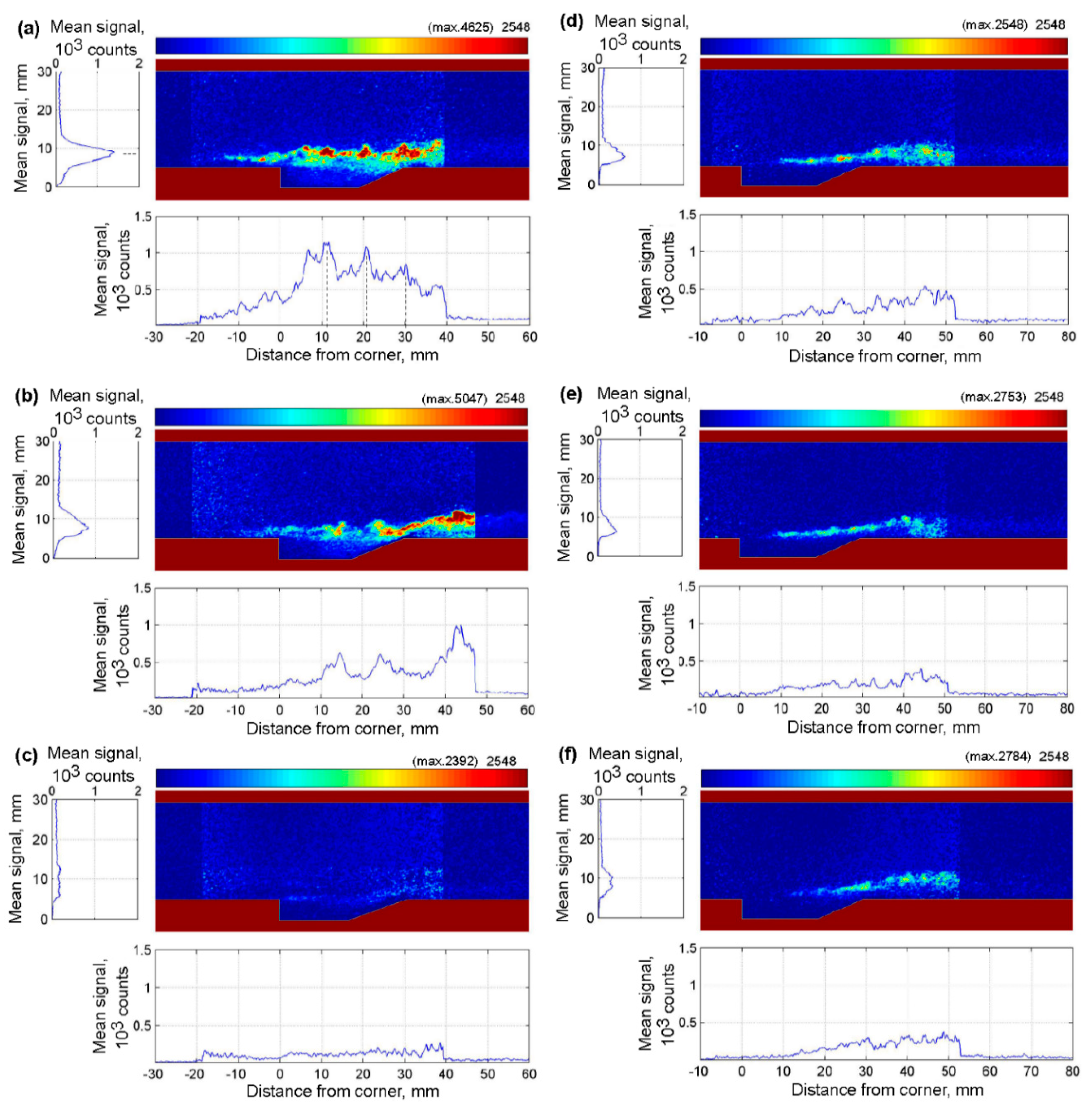
Figure 2 shows OH distributions near the cavity for the three different fuel injection types of h0 = 6.45 MJ/kg. Figure 2a,b shows the angled injection whereas Figure 2c,d shows parallel injection, and Figure 2e,f shows upstream injection. For all the images in Figure 2, the total enthalpy of the tunnel flow was h0 = 6.45 MJ/kg, except in the case of Figure 2f where h0 = 6.28 MJ/kg, even very close. The vertical and horizontal plots indicate the horizontal and vertical OH fluorescence signal counts averaged along the height and width, respectively, of the PLIF image. These plots clearly show the extent of the combusting portion of the shear layer and the distance from injection to where OH generation occurred in the flow. A region slightly downstream of the laser sheet was included in the images to allow a direct comparison of the relative size of the fluorescence and chemiluminescence signals. Note that for each of the images, the color map was scaled to the maximum signal intensity of Figure 2e, to make it easier to compare between the images. Higher signals than the maximum count were cut off to remove some artificially high signal values at the edge of the laser sheet caused by the intensity normalization procedure, where normalizing to low laser intensities at the edge of the sheet can bias the measured OH fluorescence signals. The actual maximum count for each image is shown above the color bar at the top right of each image.
At the lower equivalence ratio of Φ = 0.13, angled injection had very low OH fluorescence signals for the first 7.5 mm downstream of the injector. Generally when fuel is injected perpendicular to the floor, a bow shock develops in front of the injector and the shock-heated air ignites the fuel [30]. However, the angled injection method had an injection angle of 15° to the floor surface and did not induce as strong a bow shock as normal injection. At Φ = 0.13, the fuel did not achieve a high enough temperature for ignition, and did not penetrate as far into the air stream as it did at the higher equivalence ratio conditions; therefore, no OH signals were visible at the fuel injector location. Even though the static temperature of the incoming air was over 1500 K, the bottom wall of the duct near the fuel injector remained near room temperature because of the room-temperature wall initial condition and short duration of the shock tunnel run, combined with the much lower temperature of the fuel jet. For sonic injection at a total temperature of 296 K, the fuel had a static temperature of 246 K, so the static temperature of the mixture at the injection location was low and the flow would have a longer auto-ignition delay time. At 7.5 mm downstream of the injector, the OH fluorescence signal appeared, indicating that ignition occurred at this location due to the elevated temperature of the air and shock-heated fuel in the shear layer. In Figure 2b, the region adjacent to the injector contained flames because the recirculation zone, generated about 4 mm ahead of the injector, helped air and hydrogen fuel mix with each other at a high enough temperature to hold the flame. When the equivalence ratio increased to Φ = 0.44, high fuel injection pressure generated a weak bow shock in front of the injector and produced the high pressure and high temperature conditions required to ignite the fuel behind this shock. The region containing significant mixing due to high shear and high temperature conditions caused by the near-normal bow shock could operate as a flame holder upstream of the fuel jet. High fuel injection pressure allowed the jet to penetrate further into the supersonic air flow and allowed air to pass under the fuel jet, mixing more effectively and isolating the lower part of the fuel jet from the relatively cool wall. Hence, higher OH fluorescence signals appeared in this region as a result of combustion, and there were two major flame layers in the vertical section image. This behavior was significantly different to the case for Φ = 0.13 in Figure 2a. High OH fluorescence signals appearred periodically in the flow direction, and this trend was given conspicuously as the equivalence ratio increased. Jeong et al. [25] showed OH PLIF images and pressure distributions of the angled fuel injection method for various flow conditions using the same combustor.
For parallel fuel injection, shown in Figure 2c,d, OH fluorescence signals did not appear inside the cavity, contrary to the angled injection case. The cold fuel gas with a static temperature of 246 K entered the cavity, and a cold recirculation zone in the cavity prohibited the fuel–air mixture igniting. At low equivalence ratio condition, the supersonic flame did not penetrate into the combustor, and only propagated along the shear layer over the cavity, as shown in Figure 2c. OH florescence signals started to appear at about 13 mm downstream from the cavity leading edge in Figure 2c, so this injection type almost needed twice the ignition delay length compared with angled injection under the same flow conditions. At high equivalence ratio, as shown in Figure 2d, the flame was distributed along the cavity ramp geometry and a supersonic flame generated along the mixing layer; therefore, most of the fuel, which was injected from the front step wall, occurred near the bottom of the combustor and made a fuel layer along the cavity geometry. OH fluorescence signals started to occur 8 mm downstream of the cavity step at high equivalence ratio, demonstrating that the ignition delay length decreased as the equivalence ratio increased. Regardless of equivalence ratio, PLIF images for parallel injection did not show the OH fluorescence signals inside the cavity, which indicated that supersonic combustion did not generate in the cavity. Because the cavity was completely filled with hydrogen fuel, there was little possibility for it to mix and ignite due to lack of oxygen. Even though there was fuel–air mixture in the cavity, the cold fuel decreased the mixture temperature so that it was hard to generate the flame in the cavity. Regardless of the flame holding inside the cavity, parallel injection continuously generated a flame due to the shear layer over the cavity. Also, blowing the fuel inside the cavity, this injection method could minimize the disturbance of main air flow due to fuel injection.
Figure 2e shows the upstream fuel injection at low equivalence ratio. O’Byrne et al. [20] conducted their supersonic combustion experiments at high equivalence ratio using the same experimental facility and test model; therefore, the results of the high equivalence ratio for the upstream fuel injection was referred to from their work. In Figure 2e, upstream fuel injection showed similar flame structure to parallel fuel injection near the cavity at low equivalence ratio. Parallel and upstream fuel injections blew fuel directly into the cavity, even though their injecting directions were opposed to each other. Therefore, parallel and upstream injections formed similar fuel–air flow structures over the cavity, and similar ignition delay lengths at low equivalence ratio. Also, both injection methods did not show the OH fluorescence signals inside the cavity. Instead, the signals appeared along the shear layer over the cavity. Behind the cavity trailing edge, the OH fluorescence signals from parallel and upstream injections were distributed along the combustor’s bottom wall. These two injection methods also showed similar flame structures. However, unlike parallel injection, the flame for upstream injection of high equivalence ratio began at the leading edge of cavity, as shown in Figure 2f, and as O’Byrne et al. [20] have described. The fuel, which was injected in the opposite direction to air inflow with high injecting pressure, impacted against the cavity’s leading edge, and therefore enhanced the fuel diffusion and enabled ignition by strengthening the shockwave upstream of the injector. Therefore, even though upstream injection decreased the ignition delay length at high equivalence ratio, the main location of flame generation in this method was still in the shear layer, where fuel and air mixed, as with parallel injection, and it was difficult to find any evidence of OH production within the cavity.
Figure 3 shows supersonic flame structures near the injectors and cavity according to the change of total enthalpy of inflow with angled (Figure 3a–c) and upstream (Figure 3d–f) fuel injection types. As for Figure 2, the intensities in each image were scaled to the maximum signal in Figure 3f to facilitate comparison between images. The total enthalpies from (a) to (c) were 6.45, 5.16, and 3.82 MJ/kg, respectively, and the same enthalpies apply for Figure 3d–f. Decreasing the total enthalpy led to a decrease in the static temperature of the incoming air flow. The global equivalence ratio for Figure 3a was 0.13. As shown in Table 2, the equivalence ratio decreased by 0.02 for the lowest of the total enthalpies. As the total enthalpy of incoming air flow decreased, both fuel injection methods showed a weakening of the supersonic flame near the cavity, as the static temperature of air flow decreased. This was because the ignition delay time increased as static temperature decreased. Driscoll and Rasmussen [26] explained the flame timescales for the non-premixed case, which coincides with these experimental phenomena.
There was an obvious weakening of the flame for angled injection between the upper and lower total enthalpy limits, as shown in Figure 3a–c. On the other hand, upstream injection still had a similar flame structure for all the total enthalpies examined. Because fuel was injected in an opposite direction to the air inflow, it obstructed the air flow as it was directed up the cavity leading edge, and the speed difference between the two fluids was increased in the shear layer. Therefore, the shear layer acted as an igniter and generated a flame more easily. It should be noted, however, that at the two higher enthalpies, the angled injection generated more OH than the upstream injection configuration.
The Damköhler number is a valuable parameter for flame stabilization [31,32,33]. It has been used previously in studies of premixed combustion [34], but the experimental conditions of this study were non-premixed and required the use of a modified Damköhler number. Driscoll and Rasmussen [26] determined the flame blow-out limits using previous studies of non-premixed conditions and related the non-premixed flame timescale, τ N P , and the corresponding modified Damköhler number, D a N P , using the equation
D a N P = ( H / U A ) / τ N P .
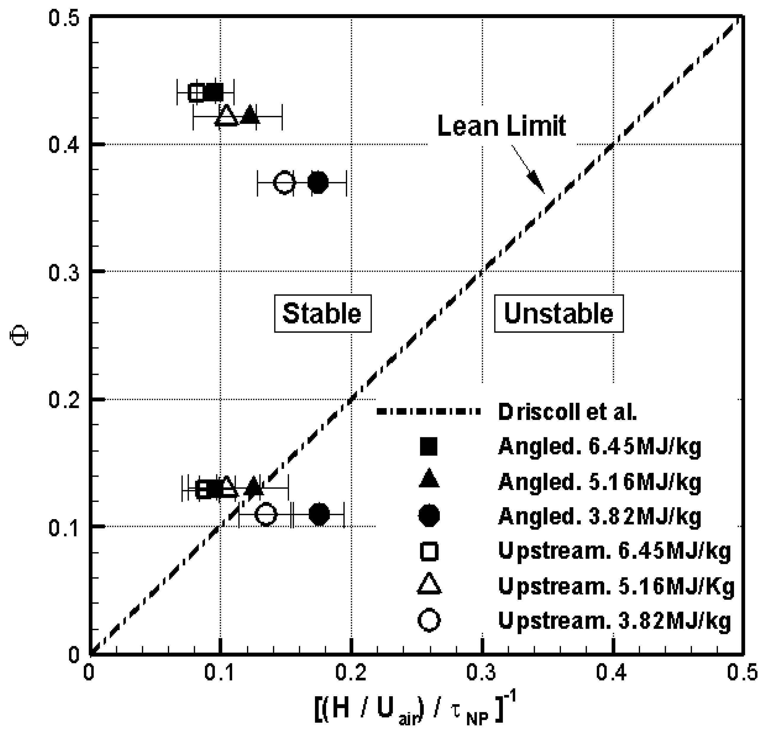
Figure 4 shows the results of comparison among the lean stable flame limits according to the fuel injection location, equivalence ratio, and correlation plots of Driscoll and Rasmussen [26]. The horizontal axis represents the inverse of the non-premixed Damköhler number and the vertical axis is the global equivalence ratio. Each horizontal error bar indicates the standard deviation of inverse Damköhler number and the error ranges of equivalence ratio are smaller than the symbol sizes. Here, two different non-premixed flame timescale, τ N P , are shown according to the global equivalence ratio was based on unity. However, the maximum global equivalence ratio in this study was below 0.5, so Figure 4 includes only the lean limit plot. Comparing the Damköhler numbers for angled fuel injection and upstream fuel injection, Figure 4 shows the effect of injection location on the flame stabilization.
At the higher equivalence ratio, the combustion occurred in the stable region of Figure 4, regardless of the fuel injection method or air flow conditions. Therefore, the cavity used in this experiment could generate and maintain the flame continuously. However, the lowest equivalence ratio showed different results according to the total enthalpy of air flow. When total enthalpies were 6.45 and 5.16 MJ/kg, the flames were located in the stable region, regardless of the fuel injection method. However, in the 3.82 MJ/kg total enthalpy case, the flame was located in the unstable region. In particular, angled injection was 60% off the Driscoll and Rasmussen’s correlation plot, and upstream injection type was 15% off at this condition. These results in Figure 4 can explain the flame near the cavity shown in Figure 3. In Figure 3a,b or Figure 3d,e, the OH fluorescence signals were clearly visible in the shear layer above the cavity, and these configurations corresponded to the stable region in Figure 4. In the case of Figure 3c, which corresponded to the location of the unstable region in Figure 4 (solid circle symbol at Φ = 0.13), the OH fluorescence signals were very weak. On the other hand, the OH fluorescence signals in Figure 3f were weak, but they were visible in the shear layer above the cavity. The results at these conditions showed the flame located in the unstable region in Figure 4 (open circle symbol) and the median value was approximately 15% off the non-premixed correlation plot. Therefore, in general, these supersonic flames agreed with the non-premixed correlation plot very well, in spite of the difference in the experimental conditions. In particular, the relation appeared to hold even at the much higher Mach number of the present experiments. Also, the non-premixed correlation plot provided useful information to determine the best cavity height to ensure stabilization of non-premixed flames.

3.2. Pressure Measurements

Figure 5 shows the comparison of static pressure for non-reacting and reacting flows with angled, parallel, and upstream fuel injections, normalised to the pressure in the nozzle reservoir of the shock tunnel. The total enthalpy of the tunnel flow was h0 = 6.45 MJ/kg. Injecting the hydrogen fuel into a nitrogen tunnel flow for a non-reacting flow allowed us to investigate the effect of fuel injection and mixing in the absence of combustion. Here, the pressure data for upstream fuel injection at high equivalence ratio, obtained by Neely et al. [21], was used to compare upstream injection pressure distributions with the two other injection methods.
At x = 293 mm, the pressure rose significantly, regardless of injection location, equivalence ratio, or whether the hydrogen was injected into nitrogen or into air. This pressure rise resulted from the reflection of the oblique shock generated by the rear wall of the cavity. For Φ = 0.13, Figure 5a,b shows similar pressure distributions for injection into nitrogen and air, everywhere except within the cavity. In the case of low equivalence ratio, the combustor geometry was a more significant factor than the location of fuel injection, as in all three cases ignition appeared to be caused by the shock reflection process. Therefore, the oblique shock from the cavity trailing edge governed the pressure distribution in the combustor in this experiment. In Figure 5a, static pressure in the cavity was lowest for angled injection, and greatest for parallel injection. As upstream and parallel injection methods injected fuel directly inside the cavity, static pressures within the cavity would obviously be greater than for angled injection. Also, parallel injection caused larger static pressure than upstream injection because the fuel, which was injected from the leading edge of the cavity, impinged on the trailing edge of the cavity. This generated an additional pressure increase within the cavity. These phenomena occurred regardless of whether or not combustion occurred, as can be seen in Figure 5b. For the reacting flow case in Figure 5b, it was only behind the shock reflection, at x = 293 mm, that weak static pressure increases occurred due to combustion heat release.
For the comparison of injection schemes at Φ = 0.44, the non-reacting flow in Figure 5c produced a similar pressure distribution regardless of fuel injection location, as was the case for the low equivalence ratio, once again excepting the cavity pressure, for the reasons explained previously. However, in Figure 5d, reacting flows at Φ = 0.44 showed different static pressure distributions when compared with the reacting flows at Φ = 0.13 in Figure 5b, and were also quite different to their equivalent non-reacting pressure distributions in Figure 5c. Even though pressure distributions up to x = 293 mm were similar for Figure 5a–c, there were significant pressure rises downstream of x = 293 mm due to heat release by combustion. This additional pressure rise was similar for both angled and parallel injection configurations, and was higher than for the upstream injection case. Therefore, high equivalence ratio flows in this paper greatly affected the combustion enhancement behind the shock reflection position and led to increases in the static pressures of the combustor by combustion heat release. This may simply have been because the higher injection pressure at the higher equivalence ratio increased the fuel jet penetration into the freestream for all three configurations, and the stronger shock made the flow more likely to ignite.
Figure 6 shows pressures inside the cavity according to fuel injection location, equivalence ratio, and the presence of combustion at a total enthalpy 6.45 MJ/kg of tunnel flow. Once fuel injection began, pressure in the cavity rose compared with the no-fuel-injection case due to the presence of the added fuel. An obvious pressure difference also occurred between reacting and non-reacting flows due to heat release. For non-reacting flows, as the equivalence ratio increased, the cavity pressures rose significantly from 54% to 70% for parallel injection and from 29% to 57% for upstream injection. However, the cavity pressure for angled injection did not change much, from 6% to 7%, as the equivalence ratio increased. These phenomena showed similar trends for reacting flows. In the cases of parallel injection and upstream injection, there was an increase with equivalence ratio, that is, an increase of fuel injection pressure brought a direct influence to pressure rise in the cavity. On the other hand, the angled injection had a small influence to change the mass flow rate in the cavity, and therefore the pressure change within the cavity was also small.
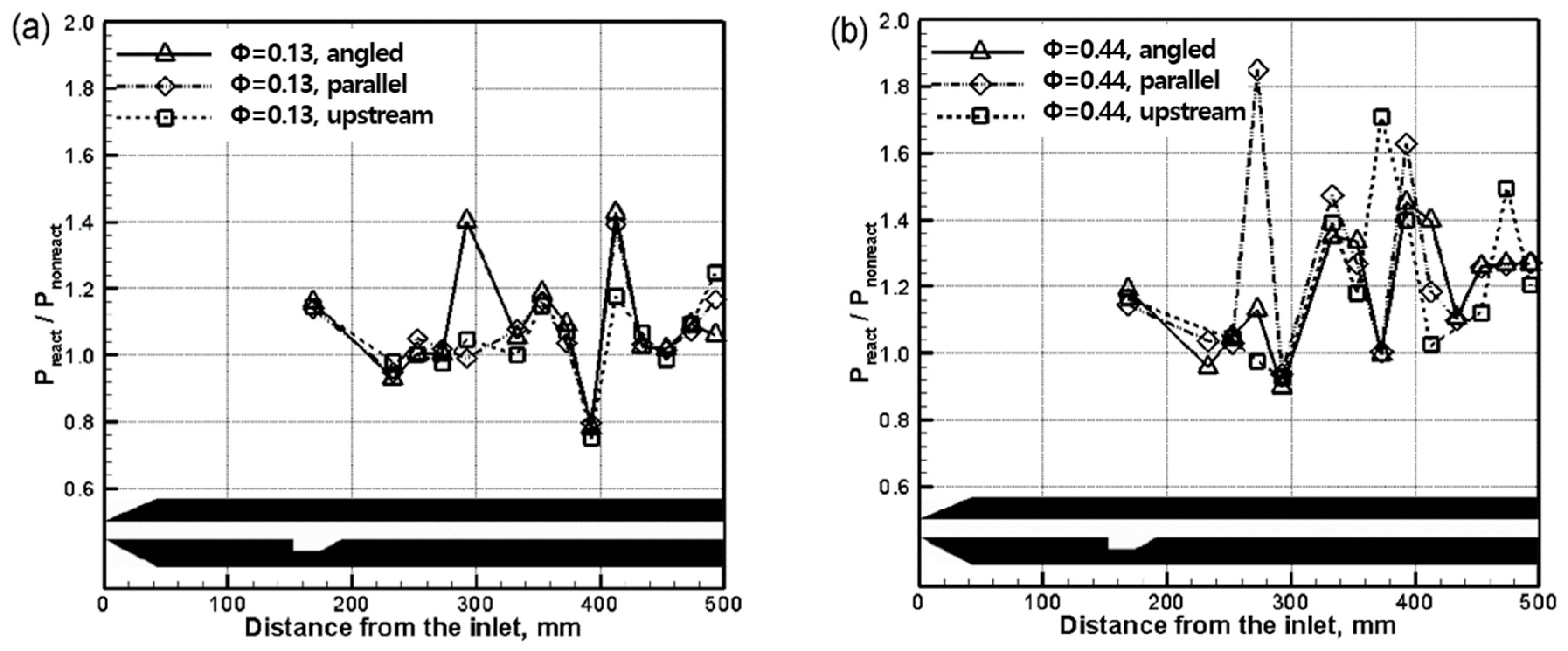
Figure 7 shows pressure ratios of reacting flows to non-reacting flows according to the fuel injection method, and it indicates the combustion effect for each of the three configurations. The total enthalpy of the test gas for these data was 6.45 MJ/kg. Figure 7a shows the pressure increase for low equivalence ratio and Figure 7b shows that for high equivalence ratio. In Figure 7a, the three different fuel injection methods had similar combustion effects for low equivalence ratio. Also, all injection methods showed approximately 18% increase in cavity pressure, showing that the cavity had an effect on ignition and flame maintenance.
In the region from the cavity’s trailing edge to x = 293 mm, the pressure ratios were almost unity. Downstream of x = 293 mm, pressure ratios increased about 15% on average for Φ = 0.13. This result came from the oblique shock generated by the cavity’s trailing edge, leading to a rise in temperature and enhanced fuel–air mixing, which leads to combustion heat release. In Figure 7b, pressure ratios in the cavity at high equivalence ratio had similar values to those at low equivalence ratio. Therefore, the difference in equivalence ratio was not closely correlated with the pressure increase in the cavity caused by combustion. At high equivalence ratio, pressure ratios downstream of the cavity were greater than unity. In particular, there was an average 30% pressure increase rate downstream of x = 293 mm. Regardless of the equivalence ratio, the pressure ratio increased gradually as it approached the end of the combustor.
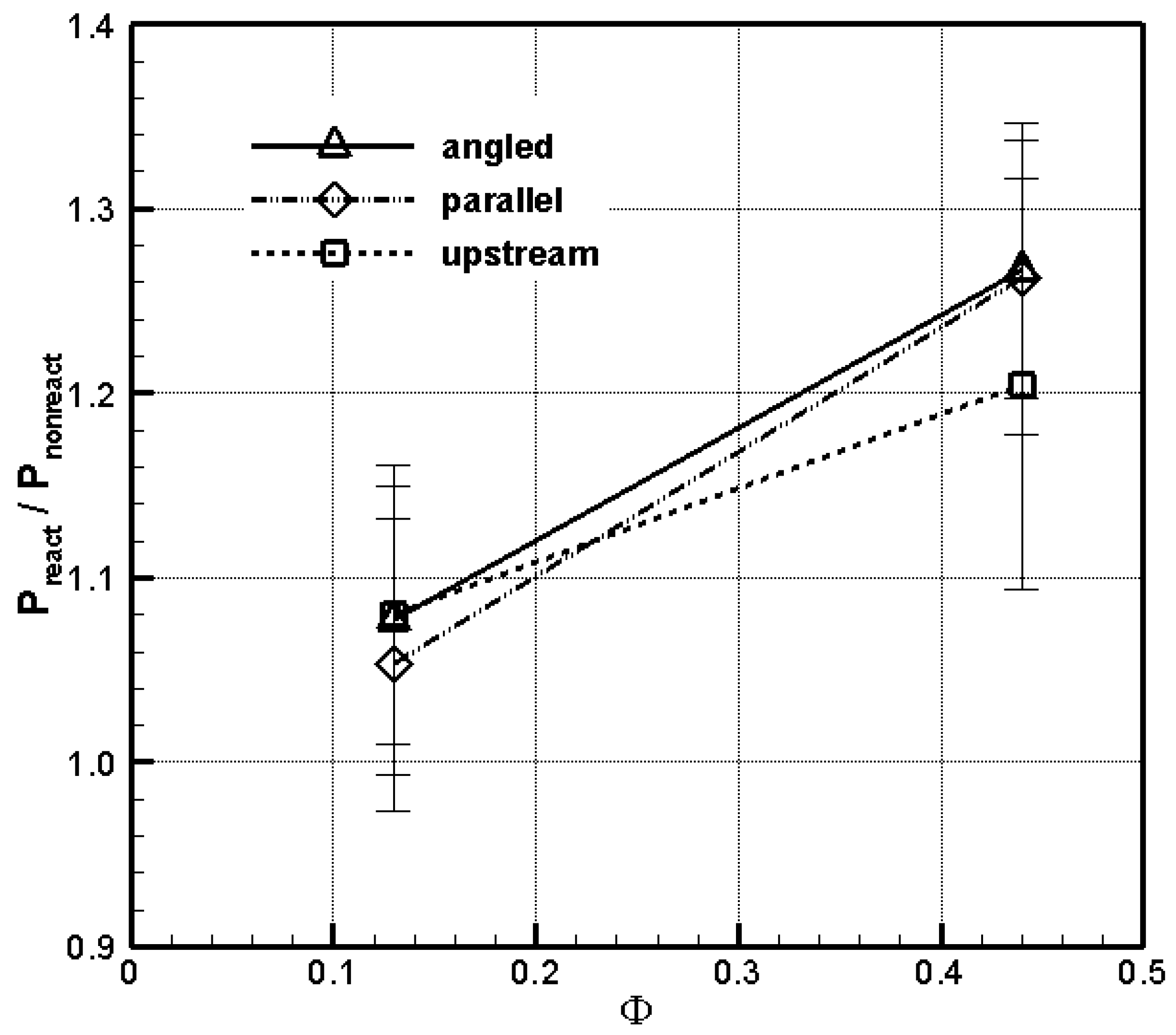
Figure 8 shows averaged ratios of reacting to non-reacting pressures for the nine pressure transducers downstream of x = 300 mm. This point was chosen for the comparison because the cavity trailing edge oblique shock reflected near x = 300 mm for all fuel injection methods, and combustion effects increased behind this point. Low equivalence ratio conditions showed similar averaged pressure ratios of about 1.05–1.08 for all injection methods. However, for the high equivalence ratio, the upstream fuel injection method showed a lower averaged pressure ratio compared with the other fuel injection methods, and this difference was about 5%, although it was within the error bars of the other two measurements. Therefore, even though the fuel injection locations were different, it had less effect on the average pressure increase downstream of the combustor in this experiment.

4. Conclusions

This paper investigated how combustion phenomena changed when the parameters of fuel injection location, equivalence ratio, and total enthalpy of test gas were varied in a model supersonic combustor with a cavity, using qualitative OH planar laser-induced fluorescence visualization and time-resolved floor static pressure measurements. The experimental results of three different fuel injection locations, several inflow total enthalpies, and global fuel-air equivalence ratios are explained as follows:
(1)
Angled fuel injection had greater fuel penetration into the air flow and enhanced both diffusion amongst the two gases and flow temperature. As the equivalence ratio increased, angled injection generated a weak bow shock in front of the injector and a recirculation zone to hold the flame. Parallel fuel injection started the ignition at the midpoint in the cavity and produced supersonic combustion only along the shear layer. For the high equivalence ratio condition, the supersonic flame developed along a single line according to the cavity geometry in the vertical section. Most of the fuel moved downstream along the bottom wall of the combustor and was not mixed actively with the air in the cavity. Therefore, the cavity inside did not hold the flame. Upstream injection showed similar flame structures to parallel injection at low equivalence ratio. However, for the high equivalence ratio condition, the fuel, which was injected in the opposite direction of air inflow with high injection pressure, impacted against the cavity’s leading edge, thus enhancing the fuel diffusion and enabling more rapid ignition. The existence of supersonic combustion near the cavity depended on the fuel injection location for the lower equivalence ratio and lower total enthalpy of air flow. The flame characteristics agreed with the correlation plot of the stable flame limit for the non-premixed condition, as defined by Driscoll and Rasmussen [26]. Using this correlation appeared to remain valid at high flight Mach number, and the plot enabled us choose combustion conditions within the stable flame limit.
(2)
For low equivalence ratio, all three injection methods for non-reacting and reacting flows showed similar pressure distributions in the combustor, except within the cavity. For reacting flows of high equivalence ratio, there were conspicuous pressure rises from x = 293 mm due to heat release by combustion for all three all injection configurations. Pressure in the cavity increased, in descending order, using angled, upstream, and parallel injection, provided the equivalence ratio was the same for the three cases. Parallel and upstream injection methods increased the cavity pressure monotonically with increasing equivalence ratio, whereas the cavity pressure of angled injection was less influenced by injection pressure. However, the pressure ratio of the cavity for reacting flows compared with non-reacting flows was around 18% for all fuel injection types and equivalence ratios.
(3)
All fuel injection types indicated similar combustion effects in the combustor and had almost unity value for the low equivalence ratio condition. At x = 293 mm behind the combustor, pressure ratios of reacting flows to non-reacting flows increased beyond unity; therefore, rising temperatures and enhanced fuel-air mixing by shock reflection increased the generation of supersonic combustion. As the equivalence ratio increased, this phenomenon appeared more pronounced.
(4)
Behind the oblique shock reflection on the combustor bottom wall, the averaged pressure ratios for low equivalence ratio were similar for all three injection methods. However, upstream injection was 5% lower than the other methods for the high equivalence ratio condition.

Author Contributions

Concept, E.J. and S.O.; method, E.J. and S.O.; software, S.O.; validation, E.J., S.O., and A.F.P.H.; formal analysis, E.J. and S.O.; resources, A.F.P.H.; data acquisition, E.J.; manuscript—original draft, E.J.; manuscript—revision, S.O. and I.-S.J.; supervision, I.-S.J. and A.F.P.H.; project administration, I.-S.J. and A.F.P.H.; funding acquisition, I.-S.J. All authors have read and agreed to the published version of the manuscript.

Funding

This research received no external funding.

Acknowledgments

This work is the result of collaboration between research groups at The Australian National University, the University of New South Wales, Australian Defence Force Academy, and Seoul National University, supported by the second stage of the Brain Korea 21 and National Research Laboratory program of KISTEP (Korea Institute of Science and Technology Evaluation and Planning, M10500000072–05J000007210). The authors wish to express their acknowledgement for the grant, and also thank to Paul Walsch for his encouraging technical effort.

Conflicts of Interest

The authors declare no conflict of interest.

Nomenclature

Llength of the cavity
Ddepth of the cavity
ushockprimary shock speed
h0total enthalpy of nozzle reservoir
ppressure
Ttemperature
ρdensity
uvelocity
MMach number
Φglobal equivalence ratio
DaNPDamköhler number for non-premixed flow
Hstep height
UAvelocity of air side of shear layer
τNPcharacteristic flame timescale for non-premixed flow
Subscripts
ostagnation condition
freestream condition
ecombustor entrance condition

References

  1. Everett, D.E.; Woodmansee, M.A.; Dutton, J.C.; Morris, M.J. Wall Pressure Measurements for a Sonic Jet Injected Transversely into a Supersonic Crossflow. J. Propuls. Power 1998, 14, 861–868. [Google Scholar] [CrossRef]
  2. VanLerberghe, W.M.; Santiago, J.G.; Dutton, J.C.; Lucht, R.P. Mixing of a Sonic Transverse Jet Injected into a Supersonic Flow. AIAA J. 2000, 38, 470–479. [Google Scholar] [CrossRef]
  3. Ben-Yakar, A.; Hanson, R.K. Experimental Investigation of Flame-Holding Capability of Hydrogen Transverse Jet in Supersonic Cross-Flow. In Twenty-Seventh International Symposium on Combustion; The Combustion Institute: Pittsburgh, PA, USA, 1998; pp. 2173–2180. [Google Scholar]
  4. Ben-Yakar, A.; Hanson, R.K. Cavity Flame-Holders for Ignition and Flame Stabilization in Scramjets: An Overview. J. Propuls. Power 2001, 17, 869–877. [Google Scholar] [CrossRef]
  5. Gruber, M.R.; Nejad, A.S.; Goss, L.P. Surface Pressure Measurements in Supersonic Transverse Injection Flowfields. In Proceedings of the 33rd AIAA/ASME/SAE/ASEE Joint Propulsion Conference & Exhibit, Seattle, WA, USA, 6–9 July 1997. [Google Scholar]
  6. Berman, H.A.; Anderson, J.D., Jr.; Drummond, J.P. Supersonic Flow over a Rearward Facing Step with Transverse Nonreacting Hydrogen Injection. AIAA J. 1983, 21, 1707–1713. [Google Scholar] [CrossRef]
  7. Abbitt, J.D.; Segal, C.; McDaniel, J.C.; Krauss, A.H.; Whitehurst, R.B. Experimental Supersonic Hydrogen Combustion Employing Staged Injection Behind a Rearward-Facing Step. J. Propuls. Power 1993, 9, 472–478. [Google Scholar] [CrossRef]
  8. Kuratani, N.; Ikeda, Y.; Nakajima, T.; Tomioka, S.; Mitani, T. Mixing Characteristics of Normal Injection into a Supersonic Backward-Facing Step Flow Measured with PIV. In Proceedings of the 40th AIAA Aerospace Sciences Meeting & Exhibit, Reno, NV, USA, 14–17 January 2002. [Google Scholar]
  9. Ikeda, Y.; Kuratani, N.; Nakajima, T.; Tomioka, S.; Mitani, T. M2.5 Supersonic PIV Measurements in a Backward-Facing Step Flow with Normal Injection. In Proceedings of the 40th AIAA Aerospace Sciences Meeting & Exhibit, Reno, NV, USA, 14–17 January 2002. [Google Scholar]
  10. Hartfield, R.J.; Hollo, S.D.; McDaniel, J.C. Experimental Investigation of a Supersonic Swept Ramp Injector Using Laser-Induced Iodine Fluorescence. J. Propuls. Power 1994, 10, 129–135. [Google Scholar] [CrossRef]
  11. Fuller, R.P.; Wu, P.K.; Nejad, A.S.; Schetz, J.A. Comparison of Physical and Aerodynamic Ramps as Fuel Injectors in Supersonic Flow. J. Propuls. Power 1998, 14, 135–145. [Google Scholar] [CrossRef]
  12. Riggins, D.W.; McClinton, C.R.; Rogers, R.C.; Bittner, R.D. Investigation of Scramjet Injection Strategies for High Mach Number Flows. J. Propuls. Power 1995, 11, 409–418. [Google Scholar] [CrossRef]
  13. Riggins, D.W.; Vitt, P.H. Vortex Generation and Mixing in Three-Dimensional Supersonic Combustors. J. Propuls. Power 1995, 11, 419–426. [Google Scholar] [CrossRef]
  14. Donohue, J.M.; McDaniel, J.C. Complete Three-Dimensional Multiparameter Mapping of a Supersonic Ramp Fuel Injector Flowfield. AIAA J. 1996, 34, 455–462. [Google Scholar] [CrossRef]
  15. Seiner, J.M.; Dash, S.M.; Kenzakowski, D.C. Historical Survey on Enhanced Mixing in Scramjet Engines. J. Propuls. Power 2001, 17, 1273–1286. [Google Scholar] [CrossRef]
  16. Fox, J.S.; Houwing, A.F.P.; Danehy, P.M.; Gaston, M.J.; Mudford, N.R.; Gai, S.L. Mole-Fraction-Sensitive Imaging of Hypermixing Shear Layers. J. Propuls. Power 2001, 17, 284–292. [Google Scholar] [CrossRef]
  17. Yu, K.H.; Wilson, K.J.; Schadow, K.C. Effect of Flame-Holding Cavities on Supersonic-Combustion Performance. J. Propuls. Power 2001, 17, 1287–1295. [Google Scholar] [CrossRef]
  18. Gruber, M.R.; Donbar, J.M.; Carter, C.D.; Hsu, K.-Y. Mixing and Combustion Studies Using Cavity-Based Flameholders in a Supersonic Flow. J. Propuls. Power 2004, 20, 769–778. [Google Scholar] [CrossRef]
  19. Rasmussen, C.C.; Driscoll, J.F.; Carter, C.D.; Hsu, K.Y. Characteristics of Cavity-Stabilized Flames in a Supersonic Flow. J. Propuls. Power 2005, 21, 765–768. [Google Scholar] [CrossRef]
  20. O’Byrne, S.; Stotz, I.; Neely, A.J.; Boyce, R.R.; Mudford, N.R.; Houwing, A.F.P. OH PLIF Imaging of Supersonic Combustion using Cavity Injection. In Proceedings of the AIAA/CIRA 13th International Space Planes and Hypersonics Systems and Technologies Conference, Capua, Italy, 16–20 May 2005. [Google Scholar]
  21. Neely, A.J.; Stotz, I.; O’Byrne, S.; Boyce, R.R.; Mudford, N.R.; Houwing, A.F.P. Flow Studies on a Hydrogen-Fueled Cavity Flame-Holder Scramjet. In Proceedings of the AIAA/CIRA 13th International Space Planes and Hypersonics Systems and Technologies Conference, Capua, Italy, 16–20 May 2005. [Google Scholar]
  22. Rasmussen, C.C.; Dhanuka, S.K.; Driscoll, J.F. Visualization of Flameholding Mechanisms in a Supersonic Combustor using PLIF. Proc. Combust. Inst. 2007, 31, 2505–2512. [Google Scholar] [CrossRef]
  23. Lin, K.; Tam, C.; Boxx, I.; Carter, C.; Jackson, K.; Lindsey, M. Flame Characteristics and Fuel Entrainment Inside a Cavity Flame Holder of a Scramjet Combustor. In Proceedings of the 43rd AIAA/ASME/SAE/ASEE Joint Propulsion Conference & Exhibit, Cincinnati, OH, USA, 8–11 July 2007. [Google Scholar]
  24. Ebrahimi, H.; Gaitonde, D.V.; Malo-Molina, F.J. Parametric Study of 3-D Hydrocarbon Scramjet Engine with Cavity. In Proceedings of the 45th AIAA Aerospace Sciences Meeting and Exhibit, Reno, NV, USA, 8–11 January 2007. [Google Scholar]
  25. Jeong, E.; O’Byrne, S.; Jeung, I.-S.; Houwing, A.F.P. Investigation of Supersonic Combustion with Angled Injection in a Cavity-Based Combustor. J. Propuls. Power 2008, 24, 1258–1268. [Google Scholar] [CrossRef]
  26. Driscoll, J.F.; Rasmussen, C.C. Correlation and Analysis of Blowout Limits of Flames in High-Speed Airflows. J. Propuls. Power 2005, 21, 1035–1044. [Google Scholar] [CrossRef]
  27. Seitzman, J.M.; Hanson, R.K. Comparison of Excitation Techniques for Quantitative Fluorescence Imaging of Reacting Flows. AIAA J. 1993, 31, 513–519. [Google Scholar] [CrossRef]
  28. McIntosh, M.K. Computer Program for the Numerical Calculation of Frozen Equilibrium Conditions in Shock Tunnels; Technical Report; Australian National University: Canberra, Australia, 1968. [Google Scholar]
  29. Vardavas, I.M. Modelling Reactive Gas Flows within Shock Tunnels. Aust. J. Phys. 1984, 37, 157–177. [Google Scholar] [CrossRef] [Green Version]
  30. O’Byrne, S. Examination of Transient Mixing and Combustion Processes in a Supersonic Combustion Ramjet Engine. Master’s Thesis, Department of Physics, Australian National University, Canberra, Australia, 1997. [Google Scholar]
  31. Baxter, M.R.; Lefebvre, A.H. Flame Stabilization in High-Velocity Heterogeneous Fuel-Air Mixtures. J. Propuls. Power 1992, 8, 1138–1143. [Google Scholar] [CrossRef]
  32. Plee, S.L.; Mellor, A.M. Characteristic Time Correlation for Lean Blowoff of Bluff-Body Stabilized Flames. Combust. Flame 1979, 35, 61–80. [Google Scholar] [CrossRef]
  33. Zukoski, E.E.; Marble, F.E. Experiments Concerning the Mechanism of Flame Blowoff from Bluff Bodies; Proceedings of the Gas Dynamics Symposium on Thermochemistry; Northwestern University: Evanston, IL, USA, 1956; pp. 205–210. [Google Scholar]
  34. Ozawa, R.I. Survey of Basic Data on Flame Stabilization and Propagation for High Speed Combustion Systems; U.S. AirForce, AFAPL Technical Report; TR-70-81 Wright-Patterson AFB: Wright-Patterson, OH, USA, 1971. [Google Scholar]
Figure 1. Schematic of cavity scramjet combustor. UV: ultraviolet.
Energies 13 00193 g001
Figure 2. OH-PLIF (planar laser-induced fluorescence) images near the cavity for the h0 = 6.45 MJ/kg air flow condition: (a) angled injection, Φ = 0.13; (b) angled injection, Φ = 0.44; (c) parallel injection, Φ = 0.13; (d) parallel injection, Φ = 0.44; (e) upstream injection, Φ = 0.13; (f) upstream injection, Φ = 0.47; h0 = 6.28 MJ/kg [20].
Energies 13 00193 g002
Figure 3. OH-PLIF images near the cavity Φ = 0.13: (a) angled injection, h0 = 6.45 MJ/kg; (b) angled injection, h0 = 5.16 MJ/kg; (c) angled injection, h0 = 3.82 MJ/kg; (d) upstream injection, h0 = 6.45 MJ/kg; (e) upstream injection, h0 = 5.16 MJ/kg; (f) upstream injection, h0 = 3.82 MJ/kg.
Energies 13 00193 g003
Figure 4. Comparison among the lean stable flame limits according to the location of fuel injection, Φ, and the correlation plot of Driscoll and Rasmussen [26].
Energies 13 00193 g004
Figure 5. Wall pressure distribution of three different fuel injections: (a) non-reacting flow, Φ = 0.13; (b) reacting flow, Φ = 0.13; (c) non-reacting flow, Φ = 0.44; (d) reacting flow, Φ = 0.44.
Energies 13 00193 g005
Figure 6. Cavity pressures according to the injection location, Φ, and combustion existence.
Energies 13 00193 g006
Figure 7. Combustion effect: (a) Φ = 0.13, (b) Φ = 0.44.
Energies 13 00193 g007
Figure 8. Averaged pressure ratios for all transducers downstream of x = 300 mm.
Energies 13 00193 g008
Table 1. Shock tube and nozzle reservoir flow properties.
Shock Tube Fill Pressure, kPaushock, km/sh0, MJ/kgp0, MPaT0, K
502.57 ± 0.036.45 ± 0.1415.7 ± 0.74422 ± 60
752.36 ± 0.035.16 ± 0.0315.0 ± 0.53855 ± 20
1252.04 ± 0.013.82 ± 0.0615.4 ± 0.63087 ± 40
Table 2. Combustor inlet conditions.
h0, MJ/kgPe, kPaTe, Kpe, kg/m3ue, m/sMe
6.45111 ± 71667 ± 600.23 ± 0.012952 ± 303.71 ± 0.03
5.16100 ± 41280 ± 100.27 ± 0.012680 ± 103.83 ± 0.01
3.8292 ± 4899 ± 200.35 ± 0.012347 ± 203.97 ± 0.01
Table 3. Fuel injection conditions.
Fuel Fill Pressure, kPaFuel Plenum Pressure, kPaFuel Injection Pressure, kPaEquivalence Ratio
h0 = 6.45 MJ/kgh0 = 5.16 MJ/kgh0 = 3.82 MJ/kg
900631 ± 21333 ± 110.130.130.11
25001906 ± 331005 ± 180.44 0.420.37