Article

Study on the Pressure-Bearing Law of Backfilling Material Based on Three-Stage Strip Backfilling Mining

1
Energy School, Xi’an University of Science and Technology, Xi’an 710054, China
2
Key Laboratory of Western Mines and Hazards Prevention, Ministry of Education of China, Xi’an 710054, China
3
Shaanxi Coal Yubei Coal Industry Co., Ltd., Yulin 719000, China
*
Author to whom correspondence should be addressed.
Energies 2020, 13(1), 211; https://doi.org/10.3390/en13010211
Submission received: 11 November 2019 / Revised: 13 December 2019 / Accepted: 27 December 2019 / Published: 2 January 2020

Abstract

:
During strip backfilling mining in coal mines, the backfilling material is the main support structure. Therefore, studying the pressure law of the backfilling material is essential for the safe and efficient mining of coal resources. Based on research into strip backfilling mining at working face number 3216 of the Shanghe Coal Mine, and to smooth transition of overlying strata loads to the backfilling material, this study proposes a three-stage strip backfilling mining method. Based on thin-plate theory, an elastic thin-plate model, a reasonable spacing of strip mining is constructed, and the reasonable mining parameters of “mining 7 m to retain 8 m” at working face number 3216 of the Shanghe Coal Mine are determined. The law of backfilling pressure in three-stage strip backfilling mining is studied through numerical simulation and physical simulation experiments. The results show that field measurement results are basically consistent with the experimental results and numerical simulation results. When three-stage strip backfilling mining is adopted, the stage-one backfilling material is the main bearing body to which the overlying rock load transfers smoothly and gradually, and the structure of the “overburden-coal pillar (or backfilling strip)” in the stope remains stable. In three-stage strip backfilling mining, the overlying rock load is ultimately transferred to the stage-one backfilling material, the stage-two backfilling material is the auxiliary bearing body, and the stage-three backfilling material mainly provides long-term stable lateral support for the stage-one backfilling material.

Graphical Abstract

1. Introduction

The ecological environment in the northern Shaanxi province of China is fragile, and it belongs to the area of “coal mining with water conservation”. Room and pillar mining (RPM), which is a simple mining method that involves less mining investment, was once a widely used mining technique for small and medium-sized coal mines in the northern Shaanxi province of China [1]. However, long-term creep of the remaining pillars in RPM is liable to cause large-scale instability of the bearing structure of overburden-pillar groups, resulting in a series of problems, such as tremors and surface subsidence [2,3,4,5]. At the same time, the recovery rate of the room pillar mining method is low. Strip backfilling mining (SBM) is superior to RPM in terms of recovery rate, surface subsidence control, and safe production [6,7,8,9,10,11]. SBM can be implemented to protect aquifers and reduce surface subsidence effectively as soil and water loss are serious in the mining area of the northern Shaanxi province; this would also help realize coal mining with water conservation [12,13,14,15]. The SBM technology is, thus, a potential solution to the above challenges.
In recent years, research on strip backfilling mining of small and medium-sized mines in China’s northern Shaanxi province has been gradually increasing [16,17,18,19,20,21]. Several scholars have studied the stability of coal pillars and overburden in SBM [22,23,24,25]. Zhang et al., among others, put forward the concept of green mining technology for “mining, selecting, and filling + X” in coal mines [26], which provided strong technical support for the so-called green coal mining. Chang et al. established a mechanical model of the roof rock beam, clarified the mechanics mechanism of controlling strata movement by backfilling mining, and provided the strata stability criterion [27]. Kostecki et al. used a numerical simulation to analyze the influence of backfilling on coal pillar strength and bearing capacity under the condition of a weak floor [28]. Xu et al. identified that SBM is an effective mining method to protect surface subsidence [29]. Zhang et al. proposed a method to control the formation and surface by using solid waste backfilling mining and discussed the future development of backfilling mining [30]. Abdelhadi evaluated mining waste and tailings through a paste backfill goaf program [31]. Sun et al. analyzed the law of rock pressure in stope under different backfilling rates by means of mechanical and numerical simulations, which provided theoretical guidance for safe and rapid production of backfilling coal mining [32]. Peng et al. analyzed the influence of silicates on the rheological properties of filler slurry [33]. Jiang et al. established the mechanics model of sub-key strata and studied the rock burst of deep strip mining [34]. Yu et al. derived simplified formulas and a methodology for stress calculations with consideration given to mine size effects and reduced the waste of coal resources from the overestimation of pillar stress [35]. Sada Haruna et al. studied the characteristics of cement fillers with a high-efficiency water reducer [36]. Yin et al. proposed a long-distance backfilling technology with a scraper winch for a steep coal seam and shortened incline length of the working face; they obtained a higher backfilling ratio [37].
Although some scholars have studied the stability of overlying strata and strip pillars (along with the related characteristics of backfilling material [38]), research on the pressure bearing law of backfilling materials (BM) remains limited [39,40,41,42]. Therefore, considering the Shanghe Coal Mine as the engineering background, this study proposes a three-stage SBM method, and the elastic thin-plate model is used to calculate the reasonable mining parameters. The objective of this study is to investigate the pressure-bearing law of BM in the Shanghe Coal Mine under three-stage SBM by using a combination of physical and numerical simulation experiments and comparing results with the field measurement results. The study provides guidance toward further understanding of the pressure-bearing law of BM in the process of coal pillar replacement and recovery and the selection of BM strength in different mining stages.

2. Experimental and Numerical Simulation Methods

2.1. Engineering Background

The Shanghe Coal Mine is located in the Yuyang District in Yulin City. It has a designed production capacity of 0.45 Mt/y and a mine area of approximately 2.97 km2. Currently, the mine is facing resource exhaustion. The primary mine here is a 3# coal seam. The RPM method was adopted in the mine before 2016. However, since then, the study of SBM has been carried out at working face number 3216 of the mine. The average dip angle of the coal seam is 0.5°; the thickness of the 3# coal seam is 6.15–6.57 m, with an average thickness of 6.34 m; and the depth of the coal seam is 100–130 m, with an average depth of 115 m. The mining height of working face number 3216 is 5.5 m, and 0.5–1.0 m where top coal is set aside. The length of the working face is 80 m.

2.2. Selection of Mining and Backfilling Methods

The purpose of SBM is to replace solid coal with the BM. In the mining process, there should be a transition stage between the overlying rock load and BM. In other words, the overlying rock load should be transferred slowly and evenly to the BM. The research divides SBM into three stages to load the BM slowly and evenly.
The first stage is strip mining is shown in Figure 1. Here, adjacent strip faces are mined in turn, and strip pillars of certain sizes are set between the two strip goafs. The second stage is the replacement and recovery of even-numbered strip coal pillars and backward arrangement of the mining technology. The third stage is the replacement and recovery of odd-numbered strip coal pillars, with backward arrangement of the mining technology. After each strip mining stage, backfilling is carried out in accordance with the forward mode.

2.3. Calculation of Strip Mining Parameters

While advancing along the strike of the strip mining face, the exposed direct roof stratum is a rectangular plate structure in space and has a fixed boundary condition on four sides. In elastic mechanics, the object enclosed by two parallel planes and cylinders perpendicular to these planes is called a plate. The distance t between the two planes is called the thickness of the plate, and the plane dividing t is called the middle plane of the plate. Considering that the thickness of the direct roof stratum is relatively small during strip mining in the Shanghe Coal Mine, and the area of the exposed roof stratum in the mining process is relatively large, the basic conditions for the study of thin plate theory are met [43].
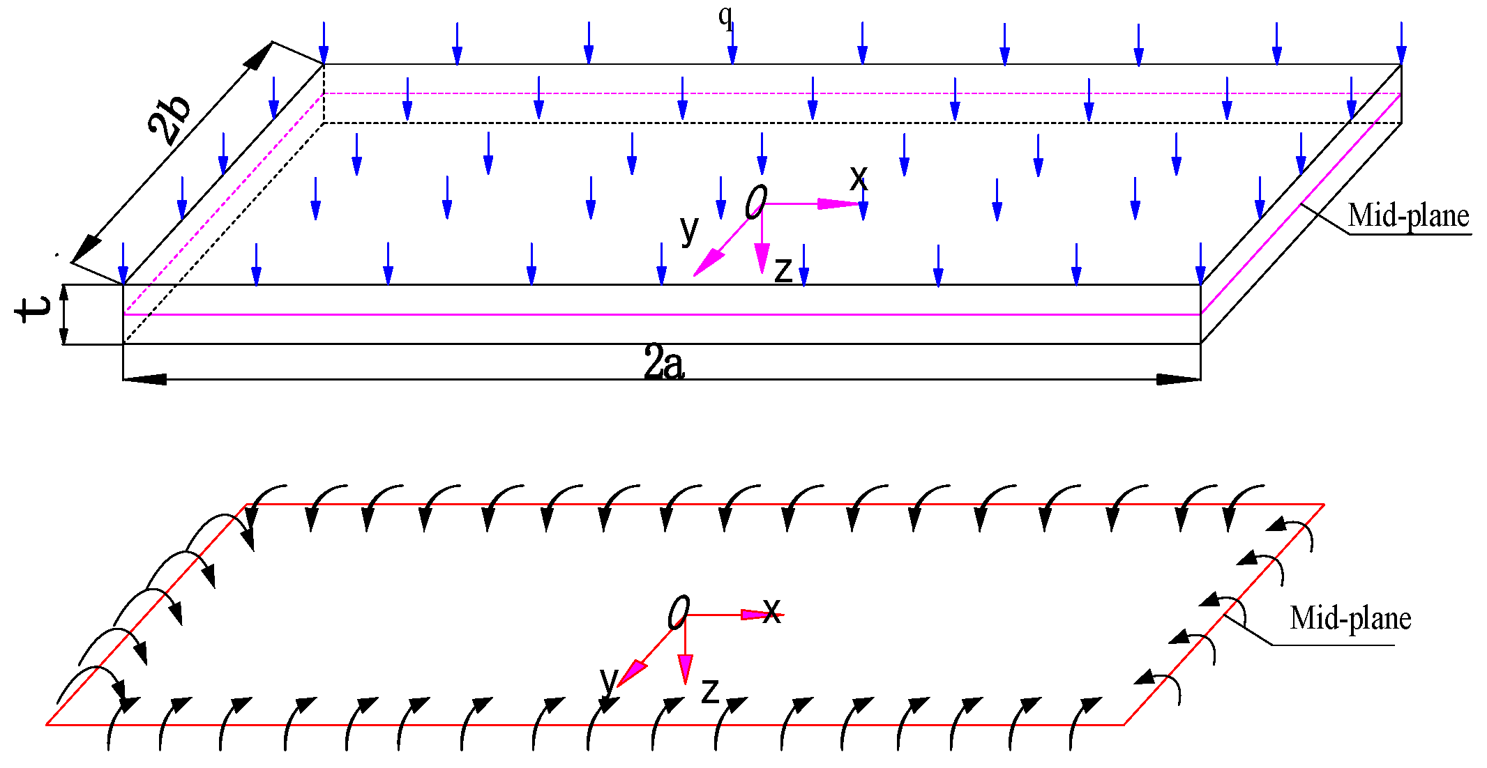
Let the edge length of the thin rectangular plate formed by the exposed direct roof strata be 2a × 2b. Parameter 2a represents the length of the working face along an inclined direction (and has a fixed value), while parameter 2b represents the distance of the working face advancing along strike (and is variable). The area around the thin rectangular plate is in a fixed state. At the same time, to simplify the calculation and consider the near-horizontal coal seam, the influence of coal seam dip is not taken into account. A Cartesian coordinate system is established at the center of the middle plane of the plate, and q is assumed to be the vertical load on the main roof. The mechanical model of the thin rock plate is shown in Figure 2.
Assuming that the rock slab material is homogeneous, continuous, and identical, the load-bearing action of the thin plate can be analyzed by using the theory of small deflection of the elastic plate. In other words, the points on the normal line of the middle surface of the thin plate (before deformation) continue to exist on the same normal line of the elastic surface after deformation, and the distance between the points on the normal line remains unchanged, while the other stresses are separated. In comparison, the stress component σ z perpendicular to the mid-plane can be ignored. This model is aimed at shallow coal seam mining in northern Shaanxi province, China. When strip backfilling mining is adopted in this area, one strip after another will be formed. The roof above the strip is not bedded intensively, so this thin plate model can be used.
The strip-mining face starts to advance from the cutting hole, and the exposed roof stratum exists as a thin plate with a fixed support on all the sides. Its boundary condition is given as follows [44]:
( ω ) x = ± a = 0 ,   ( ω ) y = ± b = 0 ,
( ω x ) x = ± a = 0 ,   ( ω y ) y = ± b = 0 ,
Under the action of load q, the thin plate deflects, and the deflection function of the plate is set as
ω = C 1 ( x 2 a 2 ) 2 ( y 2 b 2 ) 2 ,
The deformation potential energy of the plates is given as follows:
U = D 2 ( 2 ω ) 2 d x d y ,
When Equation (4) is solved, the following is obtained:
U = 8 D C 1 2 - a a b b [ ( y 2 b 2 ) 2 ( 3 x 2 a 2 ) + ( x 2 a 2 ) 2 ( 3 y 2 b 2 ) ] 2 d x d y = 256 × 126 35 × 45 D C 1 2 a 5 b 5 ( b 4 + 4 7 a 2 b 2 + a 4 ) ,
The potential energy of a normal load q N is
H = q ω d x d y = a a b b q C 1 ( x 2 a 2 ) 2 ( y 2 b 2 ) 2 d x d y = 256 225 q C 1 a 5 b 5 ,
The total potential energy of the plate is
Π = U + H ,
According to the principle of minimum potential energy, the true displacement function ω of the thin plate should minimize Π . In short, the first derivative of Π is zero.
d Π d C 1 = 0 ,
By substituting Equations (5)–(7) in Equation (8), the following results are obtained:
C 1 = 7 q 128 D ( a 4 + 4 7 a 2 b 2 + b 4 ) ,
The deflection expression is obtained by substituting C1 in Equation (3) as
ω = 7 q ( x 2 a 2 ) 2 ( y 2 b 2 ) 2 128 D ( a 4 + 4 7 a 2 b 2 + b 4 ) ,
where D is flexural rigidity of the plate and defined as D = E t 3 12 ( 1 μ 2 ) .
The stress component along the Y-axis of the thin plate can be expressed as
σ y = E z 1 μ 2 ( 2 ω y 2 + μ 2 ω x 2 ) ,
Substituting Equations (10) and (9) in Equation (11) yields:
σ y = 21 z q 8 t 3 ( a 4 + 4 7 a 2 b 2 + b 4 ) [ ( x 2 a 2 ) 2 ( 3 y 2 b 2 ) + μ ( y 2 b 2 ) 2 ( 3 x 2 a 2 ) ] ,
where t is the plate thickness and μ is Poisson’s ratio.
During the advancing process of the working face, the maximum tensile stress occurs at position x = 0 , y = ± b , z = t / 2 , meaning the middle of the long side (the length direction of the working face) of the thin stratum plate surface (the side of the back goaf). Along the y-axis direction, the value is
σ max = 21 a 4 b 2 q 8 t 2 ( a 4 + b 4 + 4 7 a 2 b 2 ) ,
With the advancing working face, tension cracks originate at the middle point of the long side of the upper surface of the thin plate’s supporting end (along the length direction of the working face). Accordingly, σ max σ s (ultimate tensile strength of the rock plate) can be used as the criterion for determining the initial breakage of the rock plate, which can be expressed as follows:
21 a 4 b 2 q 8 t 2 ( a 4 + b 4 + 4 7 a 2 b 2 ) σ s ,
The load (qn)1 of overlying n strata on the direct roof can be calculated based on the following equation [45]:
( q n ) 1 = E 1 h 1 3 ( γ 1 h 1 + γ 2 h 2 + + γ n h n ) E 1 h 1 3 + E 2 h 2 3 + + E n h n 3 ,
where E1, E2, , En is the elastic modulus of roof strata; h1, h2, , hn is the thickness of roof strata; and γ 1 , γ 2 , , γ n is the volume weight of roof strata.
If (qn+1)1 < (qn)1, the load q imposed by the overlying nth stratum on the direct roof stratum can be calculated as (qn)1.
The thickness of the immediate roof strata of Shanghe Coal Mine is 4.53 m, and the bulk density is 26.5 kN/m3, while the thickness of the feldspar sandstone is 24.51 m and the bulk density is 27.86 kN/m3. The load q1 of the immediate roof stratum is given as
q 1 = γ 1 h 1 = 26.5 × 4.53 = 120   kPa ,
The load action of the second layer on the first layer (q2)1 is as follows:
( q 2 ) 1 = E 1 h 1 3 ( γ 1 h 1 + γ 2 h 2 ) E 1 h 1 3 + E 2 h 2 3 = 1.9 × 4.53 3 × ( 26.5 × 4.53 + 27.86 × 24.51 ) 1.9 × 4.53 3 + 6.7 × 24.51 3 = 1.453   kPa < ( q 1 ) 1 ,
As a result, the middle and coarse-grained feldspar sandstone in the second layer roof is separated from the roof below. The gray mudstone in the first layer only bears its own weight. At this point, the load value on the rock layer can be considered as (q1)1 = 120 kPa, which indicates that q = q 1 = 120   kPa .
Equation (14) is suitable for the shallowly buried coal seam, as the roof is not bedded intensively. According to the geological conditions of the Shanghe Coal Mine, this formula is applicable. Four parameters of the Shanghe Coal Mine are substituted in Equation (14). Among them, the length of working face 2 a = 80 m, load q = 120 kPa on the direct roof, thickness of slab t = 2.2 m, and ultimate tensile strength of roof coal mudstone σ s = 900 kPa were used to calculate parameter b. Further, if b = 3.73 m, the strip width L = 2b = 7.46 m, and L = 7 m.
For water-conservation mining, mining should not destroy the aquifer structure. Therefore, according to Wilson’s empirical formula for the width of strip coal pillars, we calculated the width B. The empirical formula is given as follows:
B = F L + 0.02 M H 4 F ,
where B is the coal pillar width given in m; L is the strip width of 7 m; M is the coal pillar height and H is 5.5 m; the coal seam depth is 115 m; F is the safety factor of strip coal pillar, with a value of 1.3.
After substituting the data, B = 8.06 m, that is, the coal pillar width is 8 m.
The study of SBM has been carried out at working face number 3216 of the Shanghe Coal Mine. In view of its good geological conditions and stable roof, the strip mining parameters of “mining 7 m to retain 8 m” were adopted for safety reasons.

2.4. Construction of a Physical Model

A physical experimental model of 2 m × 0.2 m × 1.15 m (length × width × height) was built [46]. When the density and geometric similarity constants are chosen, the stress similarity constant of the model is obtained. The major similarity coefficients were chosen as follows: Geometric similarity ratio αL = 100, bulk density ratio αγ = 1.53, and strength ratio αR = 153. Physical experimental materials were made of river sand as aggregate, calcium carbonate and gypsum as cementitious materials, and water in an appropriate proportion. The physical model was stratified according to the different strata lithology, and a layer of mica was placed among the layers to simulate the structural planes among layers. The physical experimental material ratio of working face number 3216 is listed in Table 1.
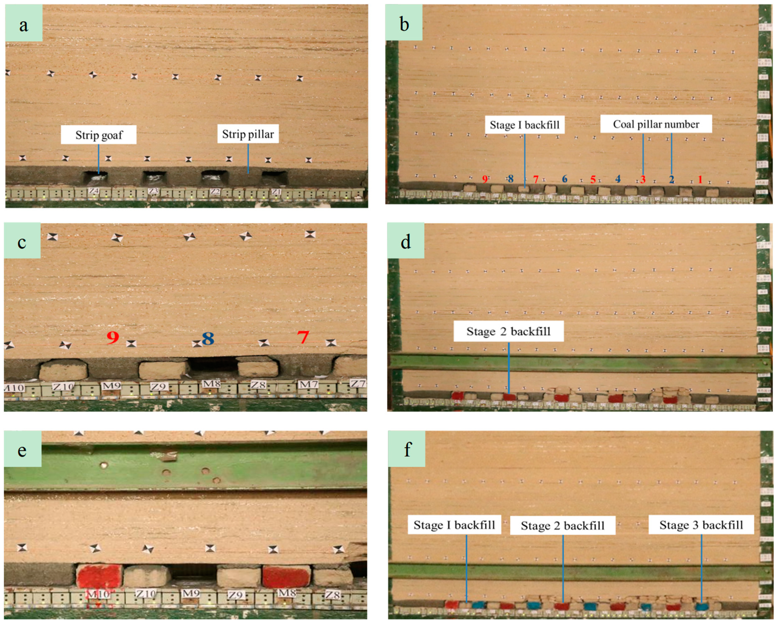
The backfilling mining of working face number 3216 in the Shanghe Coal Mine was divided into three stages. In the first stage, the strip mining method of “mining 7 m to retain 8 m” was adopted. In the second stage, even-numbered strip pillars were recovered, and odd-numbered strip pillars were recovered during the third stage. According to the backfilling mining technology, the forward backfilling mode was adopted in all three stages. As shown in Figure 3.
The key of the experiment is to prepare the BM in the strip backfilling mining, according to the mining parameters of mining 7 m to retain 8 m. In this paper, aeolian sand (a kind of yellow sand peculiar to northern Shaanxi, China), fly ash, and cement were used as physical simulation BM. Through the strength, plasticity, and other aspects of testing, it was concluded that the ratio of BM suitable for the physical simulation experiment of Shanghe Coal Mine was aeolian sand: fly ash: cement = 15:2:1. The BM at this ratio can meet the bearing capacity required by the BM in the physical experiment. The prefabricated BM is shown in Figure 4. The BM was put into the strip goaf during SBM.

2.5. Numerical Modeling

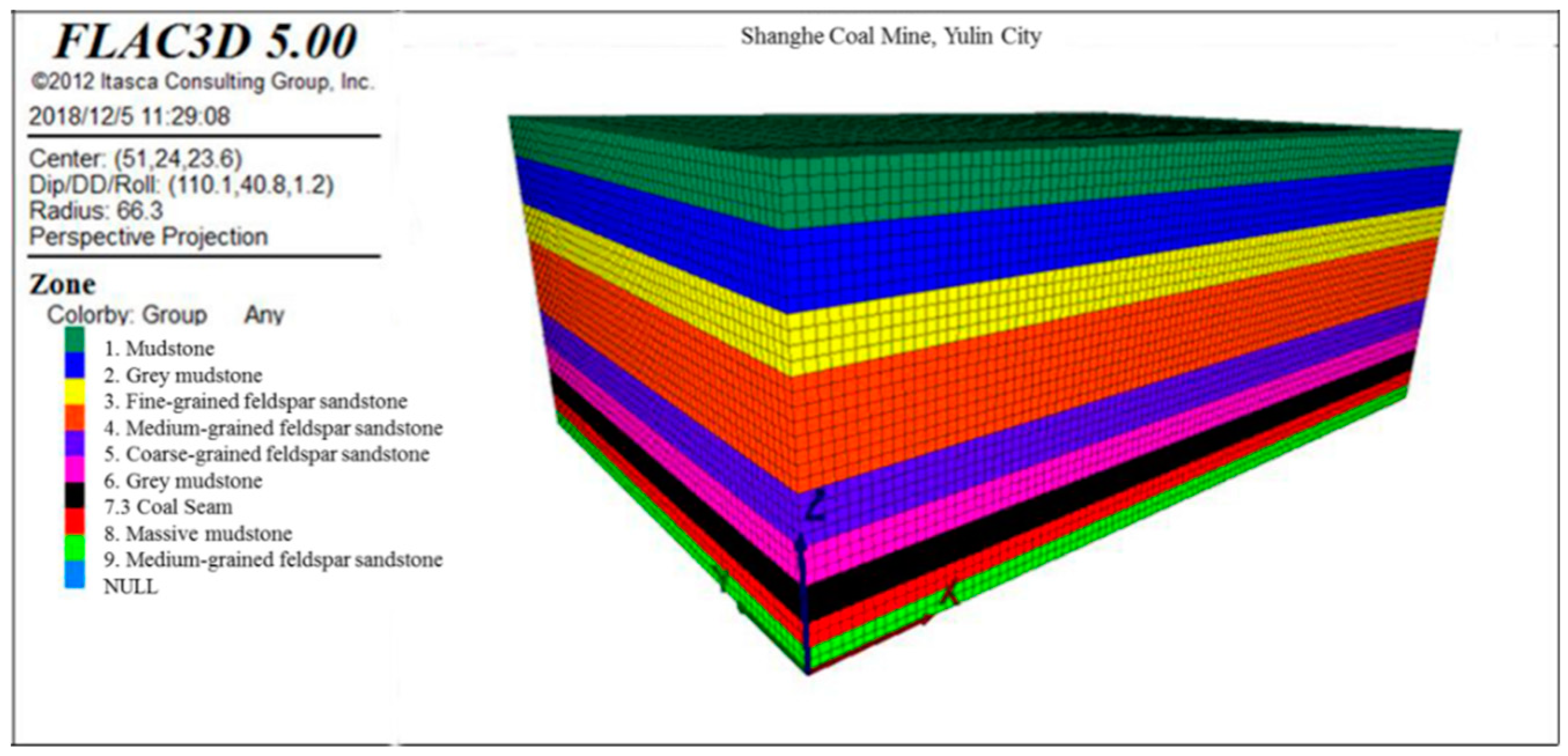
The numerical simulation model was established by combining geological engineering conditions with laboratory-measured physical and mechanical parameters of surrounding rocks. The boundary around the model is defined as a single constraint boundary, whereas the bottom boundary is defined as a full constraint boundary. The meshing model is shown in Figure 5, which consists of 231,000 units. To facilitate the study, the bedrock above is equivalent to 1.4 MPa uniform load. According to the geological engineering conditions and in situ stress data of the Shanghe Coal Mine, 4 MPa horizontal stress was applied around the model.
The Mohr–Coulomb constitutive relation was adopted in the numerical simulation model. Table 2 lists the physical and mechanical properties of rocks and BM used in the model. Among them, layer thickness was obtained based on the borehole histogram of Shanghe Coal Mine. The following parameters were measured in the laboratory: bulk density, Young’s modulus (E), Poisson’s ratio (μ), tensile strength, cohesion, and angle of internal. This was calculated by the following formula for bulk modulus (K) and shear modulus (G): K = E / 3 ( 1 2 μ ) , G = E / 2 ( 1 + μ ) .
In the numerical simulation model, the model is provided with a 20 m protective coal pillar and return air roadway. According to mining parameters of mining 7 m to retain 8 m and the three-stage SBM method, simulated mining was carried out.

2.6. Field Measurement Methods

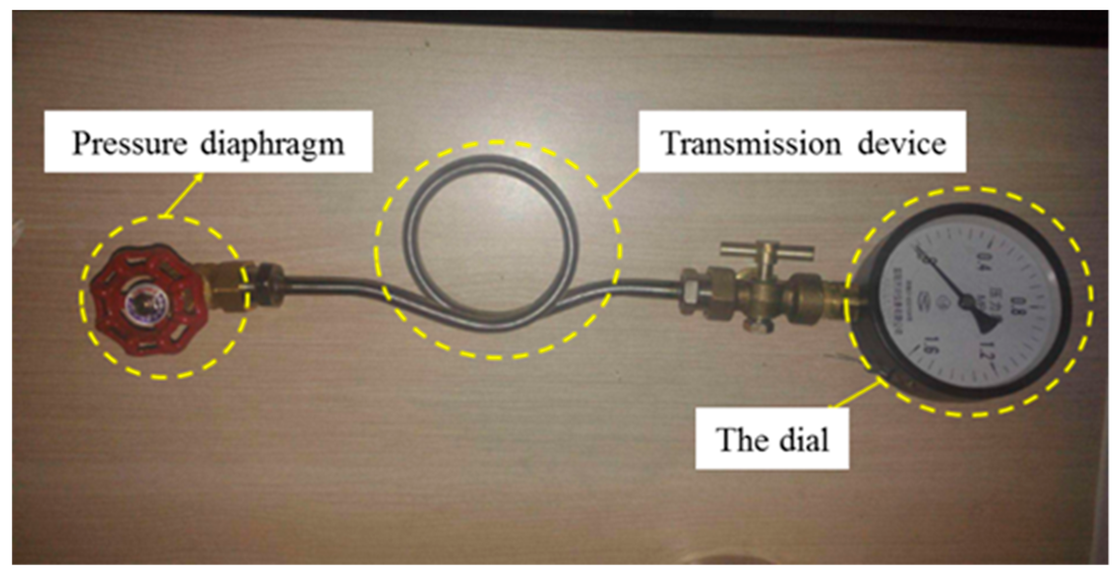
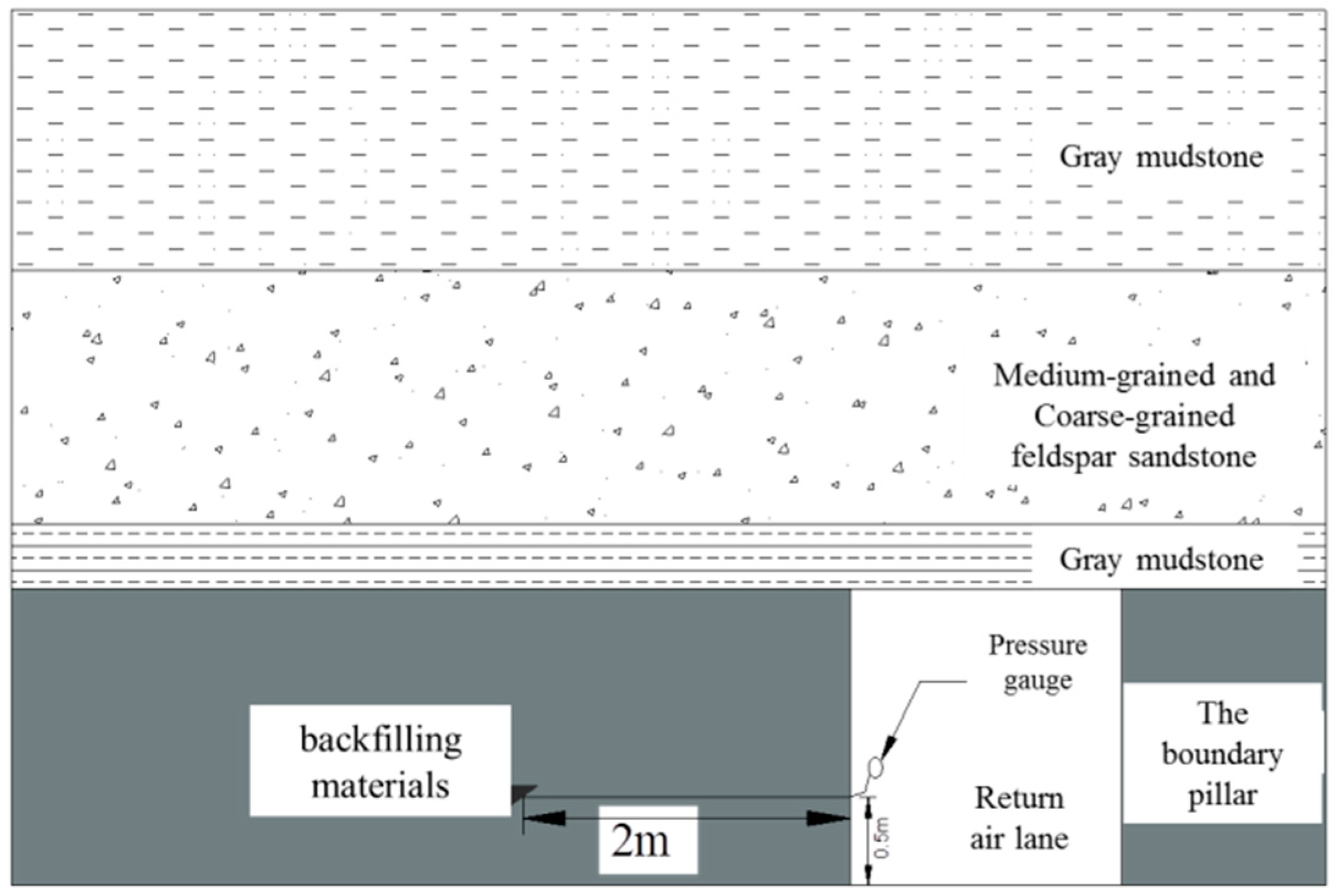
To monitor the change in pressure in BM during SBM, a diaphragm pressure gauge was embedded into BM during strip goaf backfilling. The pressure gauge model was Bzy-50 made by Kejia special pressure gauge Co., Ltd., Wuxi, China (shown in Figure 6). To eliminate the influence of the boundary effect, the diaphragm of the pressure gauge was placed 2 m away from the return air roadway and 0.5 m away from the floor of the coal seam (see Figure 7). The buried pressure gauge from the field is shown in Figure 8.

3. Results and Discussions

3.1. Results of Experimental Works

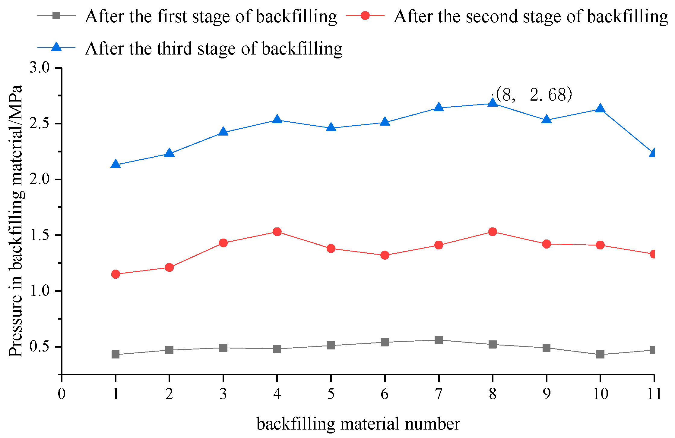
Figure 9 shows that after the first stage of backfilling, pressure in the stage-one BM was generally less than 0.5 MPa. At this point, the stage-one BM and overlying strata gradually began to come into contact. After the second stage of backfilling, the pressure of the stage-one BM increased slightly (generally between 1.0 MPa and 1.5 MPa), and the overlying strata load transferred to stage-one BM. After the third stage of backfilling, all the strip coal pillars were recovered. The pressure of the stage-one BM increased sharply to between 2.0 MPa and 4.0 MPa, and the average pressure in the BM was 2.76 MPa. At this stage, the bearing capacity of the stage-one BM reached its maximum. According to the entire mining and backfilling process of three-stage SBM, pressure in the BM generally presents in three areas, with the stress increasing and decreasing at both ends of the section, and the stress peaking in the middle of the section. The peak stress area occurs at the end of the third stage of backfilling when all the strip pillars have been recovered, and the overlying strata load is carried by the BM.
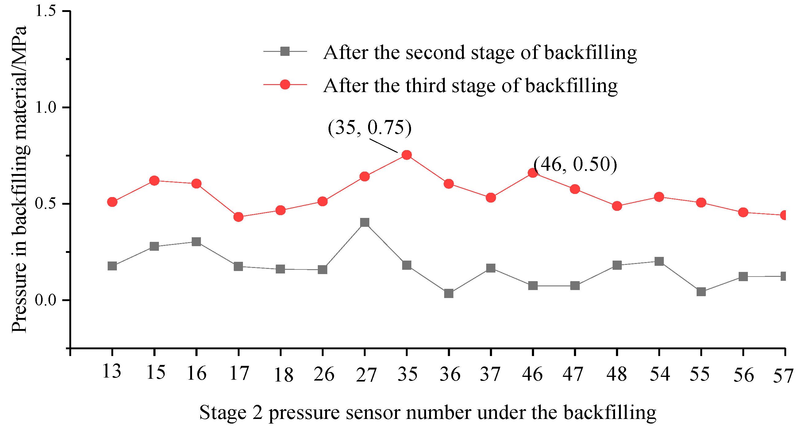
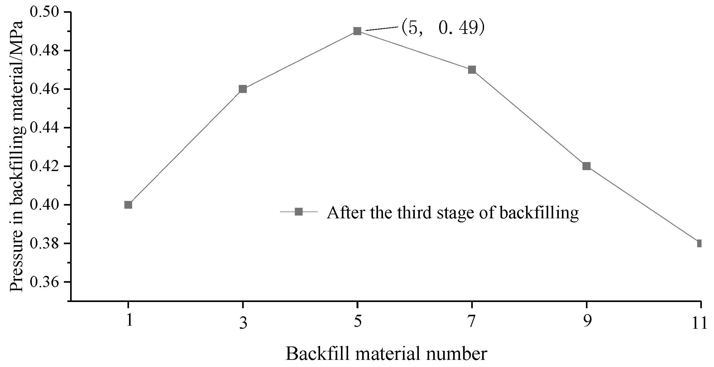
Figure 10 shows that after the second stage of backfilling, pressure in the stage-two BM was generally less than 0.5 MPa, which was similar to that of the stage-one BM. After the third stage of backfilling, pressure in the stage-two BM slightly increased and was generally between 0.5 MPa and 1.0 MPa. The stage-two BM began to bear pressure slowly. When Figure 9 and Figure 10 are compared, there is no apparent peak stress area in the entire backfilling and mining process of stage-two BM, indicating that stage-one BM bore most of the overlying strata pressure, while the stage-two BM further bore the pressure of the rock. With respect to the entire mining and backfilling process, the pressure increase in stage-two BM was more uniform and slower than that of the stage-one BM.

3.2. Numerical Modelling Results and Analysis

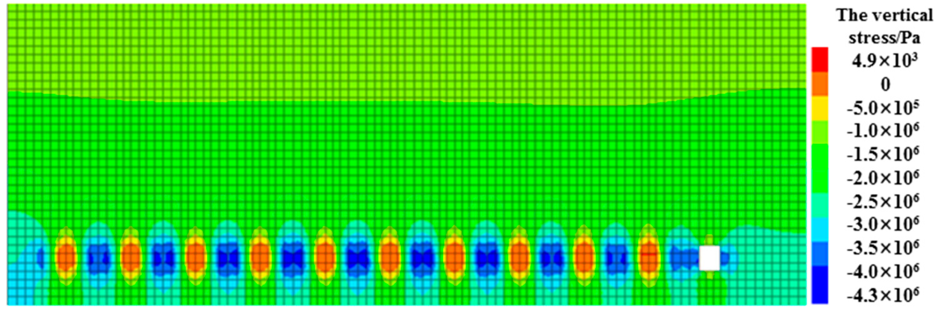
As shown in Figure 11, the average vertical stress of the first stage strip pillar was 3.5 MPa, while the maximum vertical stress was 4.3 MPa. The vertical stress of the coal pillar decreased by 0.7 MPa on average compared to that of unfilled strips. The average vertical stress of BM in the first stage was 0.8 MPa, and the bearing strength of BM increased continuously. The BM in the initial stage was not loaded during the entire backfilling process. With the advance of backfilling work, the stress value of stage-one BM began to increase, which indicates that the roof load gradually transferred to the structure of “coal pillar-backfilling material”, and although the roof load was released to a certain extent, the strip coal pillar remained the main bearing body of overlying rock load at this point.
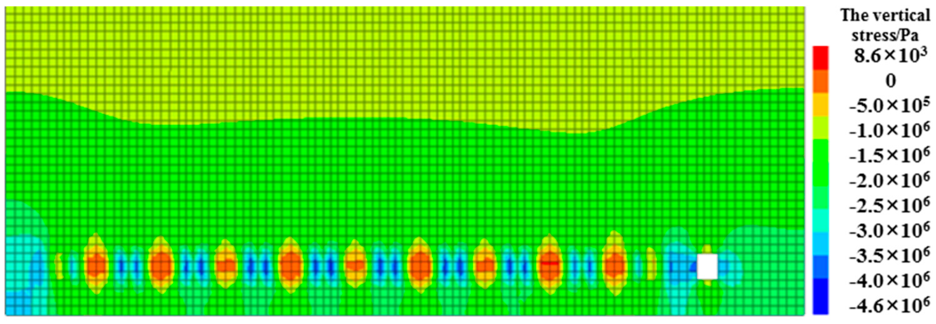
As shown in Figure 12, the second stage backfilling process showed that the stage-two BM had no bearing capacity, the average stress in the stage-one was 2.5 MPa, and the vertical stress increased significantly. The average stress of odd-numbered strip pillars was 4.0 MPa, and the stress growth of the pillars was not significant. This indicates that with continuous mining and backfilling, the roof load gradually transferred to the bearing system with stage-BM as the main support body. The roof load was further released to the BM, and the structure of “overburden-pillar-backfilling material” in the stope remained stable.
As shown in Figure 13, the third stage of the backfilling process showed that the loads of the first, second, and third stages were 3.5 MPa, 1.0 MPa and 0.5 MPa, respectively. It can be seen that most of the roof load had been transferred to the stage-one BM, and the stress of the stage-two BM gradually increased, which plays an auxiliary role in supporting the roof. In the third stage, the stage-three BM was in an unloaded state. The analysis and simulation results show that when backfilling strip goaf, three continuous forms of high strength and low strength backfilling bodies are adopted, which can help the overburden to form a good structural bearing role and ensure normal development of the backfilling mining.

3.3. Analysis of Field Measurement Results in Field Backfill Materials

We can see from Figure 14 that, after the second and third stages of backfilling mining, the pressure in the stage-one BM increased significantly, with a pressure rise from 0.5 MPa to 2.50 MPa, and the pressure value rose by about five times. According to the pressure in the stage-two BM in Figure 15, after the third stage of backfilling, the average pressure in the stage-two BM increased from 0.5 MPa to 1.4 MPa, and the pressure increased by about three times. Figure 16 shows the pressure of the stage-three BM. The pressure in the stage-three BM was distributed between 0.3 MPa and 0.5 MPa. According to the pressure distribution of the whole BM after the completion of coal pillar mining, the overburden load transferred to the stage-one BM and also to the stage-two BM, causing the pressure of the stage-one and the stage-two BM to rise.

3.4. Comparison of Experimental Results with Numerical Simulation Results and Field Measurement Results

Physical simulation experimental results show that the stage-one BM pressure increased from 0.5 MPa to between 2.0 MPa and 4.0 MPa, and the peak stress area appeared in the middle of the mining area after the third stage of backfilling, which was the main bearing body of the entire backfilling process. Pressure in the stage-two BM was between 0.5 MPa and 1.0 MPa, which was the auxiliary BM, and there was no apparent peak stress area. The numerical simulation results show that the pressure of stage-one BM increased from 0.8 MPa to 3.5 MPa, and that of stage two and three BM were 1.0 MPa and 0.5 MPa, respectively. The overburden structure of the stope was kept stable by adopting three-stage SBM. Field measurement results are as follows: The average pressure of the stage-one BM was 2.45 MPa, while for stage-two BM, it was about 1.4 MPa, and for stage-three BM, it was between 0.3 MPa and 0.5 MPa. The field measurement results are basically consistent with the experimental results.
The two experimental results coincide and consistently reflect that in the three-stage SBM process, stage-one BM plays an important role for the entire backfilling process, bearing most of the overlying strata load; stage-two BM further disperses the overlying strata load and bears a smaller proportion of the pressure, and stage-three BM presents an unloaded state. This shows that the BM can form a good bearing structure in three-stage SBM.

4. Conclusions

The following conclusions can be made from this study:
(1) Based on the thin-plate model of elasticity mechanics, the calculation model of the strip-mining width was established. Reasonable strip mining parameters of working face number 3216 in the Shanghe Coal Mine were determined. The strip-mining width was calculated to be 7 m, and the pillar width was determined to be 8 m, based on Wilson’s empirical formula.
(2) Physical simulation experimental results show that after the completion of three stages of SBM at working face 3216 of the Shanghe Coal Mine, the average pressure in the stage-one BM was 2.76 MPa, while in stage-two BM it was generally between 0.5 MPa and 1.0 MPa. The field measurement results were basically consistent with the experimental results.
(3) The numerical simulation results show that the overlying rock load can be transferred to the stage-BM smoothly and gradually by using the three-stage SBM method, and the structure of “overlying rock-coal pillar” (or backfilling strip) in the stope remains stable.
(4) In three-stage SBM, the overlying strata load is ultimately carried by stage-one BM, stage-two BM is the auxiliary bearing body, and stage-three BM mainly provides a long-term lateral support force for stage-one BM. BM of different strengths can be selected in different backfilling mining stages.

Author Contributions

Conceptualization, X.L.; Data curation, L.W.; Formal analysis, L.W.; Funding acquisition, X.S.; Investigation, Z.F. and Y.T.; Methodology, Z.F.; Project administration, L.L.; Resources, B.Z.; Software, X.L.; Supervision, X.S.; Validation, X.S.; Visualization, E.L.; Writing—original draft, X.S.; Writing—review and editing, Z.F. All authors have read and agreed to the published version of the manuscript.

Funding

This research was funded by the National Natural Science Foundation of China (Nos. 51874230, 51674188, 51874229, 51504182, 51974225, 51904224, 51904225, 51704229), the Innovation Support Program (Science and Technology Innovation Team) Project Funding of Shaanxi Province of China (No. 2018TD-038), and the Shaanxi Innovative Talents Cultivate Program-New-star Plan of Science and Technology (No. 2018KJXX-083).

Conflicts of Interest

The authors declare no conflict of interest concerning the publication of this paper.

References

  1. Xie, X.Z. Study on the characteristics of strata behavior in shallow seam longwall mining under the room-and-pillar mining goaf. J. China Coal Soc. 2012, 37, 898–902. [Google Scholar]
  2. Zhu, W.B.; Xu, J.L.; Chen, L.; Li, Z.; Liu, W.T. Mechanism of disaster induced by dynamic instability of coal pillar group in room-and-pillar mining of shallow and close coal seams. J. China Coal Soc. 2019, 44, 358–366. [Google Scholar]
  3. Zhu, W.B.; Xu, J.M.; Xu, J.L.; Chen, D.Y.; Shi, J.X. Pier-column backfill mining technology for controlling surface subsidence. Int. J. Rock Min. 2017, 96, 58–65. [Google Scholar] [CrossRef]
  4. Guan, Y.W.; Wei, Y.Q.; Yang, Z.J.; Li, Z.J.; Jun, W. Failure mechanism of the key strata-pillar system in room and pillar goaf based ona numerieal simulation. Chin. J. Geol. 2017, 28, 59–63. [Google Scholar]
  5. Jan, S.; Petr, K.; Milan, S. Seismological Activity During Room and Pillar Hard Coal Extraction at Great Depth. Procedia Eng. 2017, 191, 67–73. [Google Scholar]
  6. Fan, L.M.; Ma, X.D.; Ji, R.J. Progress in engineering practice of water-preserved coal mining in western eco-environment frangible area. J. China Coal Soc. 2015, 40, 1711–1717. [Google Scholar]
  7. Bai, E.H.; Guo, W.B.; Tan, Y.; Yang, D.M. Green coordinated mining technology of strip mining roadway backfilling method. J. China Coal Soc. 2018, 43, 21–27. [Google Scholar]
  8. Guo, G.L.; Feng, W.K.; Zha, J.F.; Liu, Y.X.; Wang, Q. Subsidence control and farmland conservation by solid backfilling mining technology. Trans. Nonferr. Metals Soc. 2011, 21, s665–s669. [Google Scholar] [CrossRef]
  9. Huang, Q.X.; He, Y.P.; Cao, J. Experimental Investigation on Crack Development Characteristics in Shallow Coal Seam Mining in China. Energies 2019, 12, 1302. [Google Scholar] [CrossRef] [Green Version]
  10. Sun, X.K.; Zhao, Q.M.; Shi, X.Y. Research and application on the technology of paste backfilling fully mechanized in residual strip pillar. J. Min. Saf. Eng. 2017, 34, 650–654. [Google Scholar]
  11. Du, X.J.; Feng, G.R.; Zhang, Y.J.; Wang, Z.H.; Guo, Y.X.; Qi, T.Y. Bearing mechanism and stability monitoring of cemented gangue-fly ash backfill column with stirrups in partial backfill engineering. Eng. Struct. 2019, 188, 603–612. [Google Scholar] [CrossRef]
  12. Liu, J.; Sui, W.; Zhao, Q. Environmentally sustainable mining: A case study of intermittent cut-and-fill mining under sand aquifers. Environ. Earth Sci. 2017, 76, 562. [Google Scholar] [CrossRef] [Green Version]
  13. Tang, W.J.; Sun, X.K.; Wang, H.; Shi, X.Y.; Li, X.Y.; Li, Y. Study on effect of overlying strata stability during strip coal pillar excavation with paste backfilling. Coal Sci. Technol. 2017, 45, 109–115. [Google Scholar]
  14. Du, X.J.; Feng, G.R.; Qi, T.Y.; Guo, Y.X.; Zhang, Y.J.; Wang, Z.H. Failure characteristics of large unconfined cemented gangue backfill structure in partial backfill mining. Constr. Build. Mater. 2019, 194, 257–265. [Google Scholar] [CrossRef]
  15. Mu, W.Q.; Li, L.C.; Guo, Z.P.; Du, Z.W.; Wang, S.X. Novel Segmented Roadside Plugging-Filling Mining Method and Overlying Rock Mechanical Mechanism Analyses. Energies 2019, 12, 2073. [Google Scholar] [CrossRef] [Green Version]
  16. Cao, W.H.; Wang, X.F.; Li, P.; Zhang, D.S.; Sun, C.D.; Qin, D.D. Wide Strip Backfill Mining for Surface Subsidence Control and Its Application in Critical Mining Conditions of a Coal Mine. Sustainability 2018, 10, 700. [Google Scholar] [CrossRef] [Green Version]
  17. Zhang, J.X.; Zhang, Q.; Ju, F.; Zhou, N.; Li, M.; Sun, Q. Theory and technique of greening mining integrating mining, separating and backfilling in deep coal resources. J. China Coal Soc. 2018, 43, 377–389. [Google Scholar]
  18. Sun, Q.; Zhang, J.X.; Yin, W.; Zhou, N.; Liu, Y. Study of stability of surrounding rock and characteristic of overburden strata movement with longwall roadway backfill coal mining. J. China Coal Soc. 2017, 42, 404–412. [Google Scholar]
  19. Fan, D.Y.; Liu, X.S.; Tan, Y.L.; Song, S.L.; Gu, Q.H.; Yan, L.; Xu, Q. Roof Cutting Parameters Design for Gob-Side Entry in Deep Coal Mine: A Case Study. Energies 2019, 12, 2032. [Google Scholar] [CrossRef] [Green Version]
  20. Han, J.H.; Zou, J.Q.; Hu, C.C.; Yang, W.H. Study on Size Design of Shaft Protection Rock/Coal Pillars in Thick Soil and Thin Rock Strata. Energies 2019, 12, 2553. [Google Scholar] [CrossRef] [Green Version]
  21. Ju, F.; Huang, P.; Guo, S.; Xiao, M.; Lan, L.X. A roof model and its application in solid backfilling mining. Int. J. Min. Sci. Technol. 2017, 27, 139–143. [Google Scholar] [CrossRef]
  22. Huang, Q.X.; He, Y.P. Research on Overburden Movement Characteristics of Large Mining Height Working Face in Shallow Buried Thin Bedrock. Energies 2019, 12, 4208. [Google Scholar] [CrossRef] [Green Version]
  23. Zhu, X.J.; Guo, G.L.; Liu, H.; Chen, T.; Yang, X.Y. Experimental research on strata movement characteristics of backfill–strip mining using similar material modeling. Bull. Eng. Geol. Environ. 2019, 78, 2151–2167. [Google Scholar] [CrossRef]
  24. Kong, P.; Jiang, L.S.; Shu, J.M.; Wang, L. Mining Stress Distribution and Fault-Slip Behavior: A Case Study of Fault-Influenced Longwall Coal Mining. Energies 2019, 12, 2494. [Google Scholar] [CrossRef] [Green Version]
  25. Zhu, W.B.; Yu, S.C.; Xuan, D.Y.; Shan, Z.J.; Xu, J.L. Experimental study on excavating strip coal pillars using caving zone backfill technology. Arab. J. Geosci. 2018, 11, 554. [Google Scholar] [CrossRef]
  26. Zhang, J.X.; Zhang, Q.; Ju, F.; Zhou, N.; Li, M.; Zhang, W.Q. Practice and technique of green mining with integration of mining, dressing, backfilling and X in coal resources. J. China Coal Soc. 2019, 44, 64–73. [Google Scholar]
  27. Chang, Q.L.; Zhou, H.Q.; Bai, J.B.; Duan, C.R.; Li, Y.W. Stability Study and Practice of Overlying Strata with Paste Backfilling. J. Min. Saf. Eng. 2011, 28, 279–282. [Google Scholar]
  28. Kostecki, T.; Spearing, A.J.S. Influence of backfill on coal pillar strength and floor bearing capacity in weak floor conditions in the Illinois Basin. Int. J. Rock Mech. Min. 2015, 76, 55–67. [Google Scholar] [CrossRef]
  29. Xu, J.L. Strata control and scientific coal mining—A celebration of the academic thoughts and achievements of Academician Ming gao Qian. J. Min. Saf. Eng. 2019, 36, 1–6. [Google Scholar]
  30. Zhang, J.X.; Li, M.; Abbas, T.; Zhang, W.Q.; Wu, Z.Y.; Song, W.J. Properties and application of backfill materials in coal mines in China. Minerals 2019, 9, 53. [Google Scholar] [CrossRef] [Green Version]
  31. Khaldoun, A.; Ouadif, L.; Baba, K.; Bahi, L. Valorization of mining waste and tailings through paste backfilling solution, Imiter operation, Morocco. Int. J. Min. Sci. Technol. 2016, 26, 146–151. [Google Scholar] [CrossRef]
  32. Sun, Q.; Zhang, J.X.; Ju, F.; Zhou, N.; Zhang, Q. Laws and mechanism of strata behaviors in backfill mining. J. Min. Saf. Eng. 2017, 34, 310–316. [Google Scholar]
  33. Xiapeng, P.; Fall, M.; Haruna, S. Sulphate induced changes of rheological properties of cemented paste backfill. Miner. Eng. 2019, 141, 105849. [Google Scholar] [CrossRef]
  34. Jiang, F.X.; Weng, J.L.; Bai, W.S.; Wang, G.L.; Li, M. Rock burst risk in surrounding abscission layer of overlying high key strata in deep strip mining mines. J. China Univ. Min. Technol. 2018, 47, 40–47. [Google Scholar]
  35. Yu, Y.; Deng, K.Z.; Chen, S.E. Mine Size Effects on Coal Pillar Stress and Their Application for Partial Extraction. Sustainability 2018, 10, 792. [Google Scholar] [CrossRef] [Green Version]
  36. Sada, H.; Mamadou, F. Time- and temperature-dependent rheological properties of cemented paste backfill that contains super plasticizer. Powder Technol. 2019, 360, 731–740. [Google Scholar]
  37. Yin, Y.C.; Zhao, T.B.; Zhang, Y.B.; Tan, Y.L.; Qiu, Y.; Taheri, A.; Jing, Y. An Innovative Method for Placement of Gangue Backfilling Material in Steep Underground Coal Mines. Minerals 2019, 9, 107. [Google Scholar] [CrossRef] [Green Version]
  38. Chen, S.J.; Du, Z.W.; Zhang, Z.; Zhang, H.W.; Xia, Z.G.; Feng, F. Effects of chloride on the early mechanical properties and microstructure of gangue-cemented paste backfill. Constr. Build. Mater. 2020, 235, 117504. [Google Scholar] [CrossRef]
  39. Huang, Y.C.; Wu, Y.; Chang, J. Application and Technology of Coal Mining with Paste like Roadway Backfill. Coal Sci. Technol. 2014, 342, 253–2336. [Google Scholar]
  40. Li, J.M.; Huang, Y.L.; Chen, Z.W.; Zhang, J.X.; Jiang, H.Q.; Zhang, Y.C. Characterizations of macroscopic deformation and particle crushing of crushed gangue particle material under cyclic loading: In solid backfilling coal mining. Powder Technol. 2019, 343, 159–169. [Google Scholar] [CrossRef]
  41. Liu, K.; Zhou, H.Q.; Zheng, L.J.; Li, L. Strip Mining Technology with Paste Backfilling. Coal Sci. Technol. 2010, 38, 10–14. [Google Scholar]
  42. Wang, F.; Jiang, B.Y.; Chen, S.J.; Ren, M.Z. Surface collapse control under thick unconsolidated layers by backfilling strip mining in coal mines. Int. J. Rock Mech. Min. 2019, 113, 268–277. [Google Scholar] [CrossRef]
  43. Xu, Z.L. A Concise Course on Elasticity; Higher Education Press: Beijing, China, 2013; pp. 197–198. [Google Scholar]
  44. Shao, X.P. Basic Research on Control of Surrounding Rock in Big Section Safety Mining in Steep Seams; Xi’an University of Science and Technology: Xi’an, China, 2008; pp. 73–75. [Google Scholar]
  45. Qian, M.G. Mining Pressure and Strata Control; University of Mining and Technology Press: Xuzhou, China, 2010; pp. 79–80. [Google Scholar]
  46. Huang, Q.X.; Cao, J. Research on Coal Pillar Malposition Distance Based on Coupling Control of Three-Field in Shallow Buried Closely Spaced Multi-Seam Mining, China. Energies 2019, 12, 462. [Google Scholar] [CrossRef] [Green Version]
Figure 1. Schematic diagram of three-stage strip backfilling mining.
Energies 13 00211 g001
Figure 2. Mechanical model of a thin rock plate.
Energies 13 00211 g002
Figure 3. Physical experimental process of three-stage backfilling mining: (a) The third coal pillar chart in the first stage; (b) backfilling the first stage strip gap; (c) phase II recovery of M8 coal pillar; (d) backfilling the strip gap in the second stage; (e) phase III recovery of M9 coal pillar; (f) phase III backfilling strip goaf.
Energies 13 00211 g003
Figure 4. Backfilling material.
Energies 13 00211 g004
Figure 5. The numerical model.
Energies 13 00211 g005
Figure 6. Bzy-50 diaphragm pressure gauge.
Energies 13 00211 g006
Figure 7. Diaphragm pressure gauge layout.
Energies 13 00211 g007
Figure 8. Site pressure gauge embedded drawing.
Energies 13 00211 g008
Figure 9. Pressure of the stage-one backfilling materials (BM) in three stages.
Energies 13 00211 g009
Figure 10. Pressure of the stage-two BM in two stages.
Energies 13 00211 g010
Figure 11. Simulation of stress evolution in the first stage of the backfilling process.
Energies 13 00211 g011
Figure 12. Simulation of stress evolution in the second stage of the backfilling process.
Energies 13 00211 g012
Figure 13. Simulation of stress evolution in the third stage of the backfilling process.
Energies 13 00211 g013
Figure 14. Stage-one BM pressure value.
Energies 13 00211 g014
Figure 15. Stage-two BM pressure value.
Energies 13 00211 g015
Figure 16. Stage-three BM pressure value.
Energies 13 00211 g016
Table 1. Physical experimental material ratio of working face number 3216.
NameLayer Thickness (m)Model Layer Thickness (cm)Match Ratio NumberConsumables (kg)
SandGypsumCalcium CarbonateCoal Ash
Sandy loess47.81489285.760.130.51
Mudstone10.93116465.480.360.56
Gray mudstone12.99137285.60.160.64
Fine-grained feldspar sandstone7.2677375.60.240.56
Medium-grained feldspar sandstone15.23157465.60.320.48
Coarse-grained feldspar sandstone9.1998465.690.280.43
Gray mudstone4.5357285.60.160.64
3# Coal6.34621:1:2:212.990.140.282.99
Table 2. List of the physical and mechanical properties of rocks and backfilling materials (BM).
NameLayer Thickness (m)Bulk Density (kN/m3)Bulk Modulus (GPa)Shear Modulus (GPa)Tensile Strength (MPa)Cohesion (MPa)Angle of Internal Friction (°)
Mudstone10.9324.93.682.11.21.525
Gray mudstone12.9925.83.562.11.21.335
Fine-grained feldspar sandstone7.2625.68.824.842.93.031
Medium-grained feldspar sandstone15.2324.88.824.842.93.031
Coarse-grained feldspar sandstone9.1927.87.873.832.52.833
Gray mudstone4.5326.53.562.10.91.227
3# Coal6.3414.32.351.471.11.730
Massive mudstone4.2926.53.632.21.21.431
Medium-grained feldspar sandstone7.3223.68.824.842.93.129
Backfill materials5.521.04.32.31.24.237