1. Introduction
Hybrid electric vehicles received much attention in the past few decades due to urgent concerns about the emission of carbon and exhaust gases. The reasons are that, on the one hand, the energy efficiency of the entire powertrain can be enhanced so that the emission of carbon can be reduced; on the other hand, the purely electric drive and smoothness of engine operation during city driving can effectively reduce the emission of exhaust gases [
1]. The architectures of hybrid electric vehicles (HEVs) can be divided into two types: series and parallel HEVs [
2]. The series operation can solve the problems of low efficiency and high fuel consumption caused by cold starting and the preheating process of engines [
3]. Furthermore, ultracapacitors can be used as energy storage systems. Their capacities can affect the times of engine starting. The kinetic energy of vehicles can be restored using regenerative braking. Therefore, the comfort and system efficiency of the integrated powertrain can be improved [
2]. Furthermore, if the reactively controlled compression ignition (RCCI) engines can be implemented into a series HEV, not only can the feature of good fuel economy be promoted, but the advantages of low emissions of nitrogen oxides (NO
x) and particulate matter (PM) can also be gained [
4]. As for the parallel HEVs, the flexibility of utilizing multiple energy storage systems and electric power systems possesses the potential of further reducing fuel consumption, as well as emissions of pollutants. Moreover, compared with conventional vehicles, the energy management strategies can be designed through optimal numerical analysis without sacrificing their drivability [
5]. However, the relatively complicated architectures of parallel HEVs result in a higher cost of manufacture and maintenance [
6]. Unlike conventional vehicles with internal combustion engines, one of the effective ways to improve fuel economy and emissions of pollutants is utilizing the optimal strategy of energy management [
7]. An efficient strategy of energy management for real-time control can be designed through a simulation on an entire power system. This is further modified according to effective engineering experiences. Consequently, the resulting performances of the designed vehicle can be significantly improved especially when dealing with some rather complicated architectures of powertrain [
8]. Currently, when facing an urgent impact of ISO 26262, global industries of vehicles, such as factories of original equipment manufacturing (OEM), tier 1 components, vehicular chips, and development tools, started implementing ISO 26262 in the processes of product development or adjusting the software/hardware development tools to meet the requirements of ISO 26262 [
9]. To efficiently simplify the extremely high-level and complicated tasks of vehicle dynamic computations, the required core technology will definitely involve low-cost and high-efficiency embedded systems that are integrated with software and hardware and capable of customization of the basic architecture for computing according to the specific functionality [
10]. Currently, a real-time simulation coupled with the hardware-in-the-loop (HIL) platform is widely applied in industry [
11,
12]. A performance evaluation on a hybrid electric system called a molten carbonate fuel cell/micro gas turbine (MCFC-MGT) using an HIL simulation was proven to be an effective means of saving development cost [
13]. Furthermore, when performing tests on flexible alternating current transmission systems (FACTSs) under either conventional or newly revised industry specifications, the HIL simulations are regarded as an efficient testing method prior to the actual field tests [
14].
With regard to past studies, the main goal to optimize synergy/electricity systems is enhancing the energy efficiency and performance of an entire system for fuel saving coupled with cost reduction. Accordingly, two major factors are the strategy of energy management and design of the synergy/electricity powertrain. For the optimization of the former, especially on HEVs, one of the widely applied control methods is rule-based control (RBC) [
15]. Its advantages are easy implementation, highly efficient computation, and fast experimental verification. However, its inherent propensity to evaluate by engineering intuition showed its weakness when dealing with rather complicated and highly nonlinear systems. To overcome this and enhance robustness due to system uncertainty, fuzzy logic control (FLC) was introduced, and it is especially applicable to various types of HEVs [
16,
17]. Sunddararaj et al. proposed the proportional/integral and fuzzy logic control strategies for direct current DC/DC converters. This hybrid controller further improved the performance of the bi-directional DC/DC converter and the power circuits for voltage gain, filtering, system efficiency, and electricity quality [
18]. However, for systems with considerable numbers of control variables requiring a mass of logical rules for effective control, a global search using equivalent consumption minimization strategies (ECMS) is adopted for optimization in a more numerically precise manner [
19,
20]. Multi-dimensional look-up tables derived from the simulated results based on the ECMS concept can be constructed through computer coding and directly downloaded to the control unit to realize the practical implementation of optimal energy management in the synergy/electricity powertrains. This research can be employed for other types of electric vehicles as long as the characteristics of energy/power sources are built and the objective function (goal) is set. The major advantage of EMCS is to accommodate both the theoretical optimization analysis and the direct usage for the control unit because of the resulting matrix. The drawback is that, compared with the time-independent or predictive control laws (such as dynamics programming), the ECMS optimization cannot handle the system constraints (such as the start-to-end balance for state of charge). However, to deal with the unknown out loads and the complicated system dynamics, it is one of the best candidates for the optimization [
21]. Other algorithms are introduced in the paragraph below.
The dynamic programming (DP) algorithm is a commonly used approach for optimization. Basically, the optimal scheme for power distribution can be precisely calculated based on known driving cycles [
22,
23]. However, traditional DP can only be used to attain the optimal solutions under the designated driving cycles rather than the unpredictable driving patterns in reality. An evolved approach from DP called stochastic dynamic programming (SDP) is capable of dealing with uncertain situations during actual driving and, thus, may further extend the application to real-time control [
24]. However, the undesirably high computing load and sophisticated derivation of mathematics limit its application to the practical control of vehicles. Alternatively, the genetic algorithm (GA) is a feasible method to obtain accurate solutions especially for the control systems of vehicles with high nonlinearity [
25]. Other control strategies such as bionic optimization algorithms (e.g., particle swarm optimization, bacterial foraging algorithm, etc.) can search for the best solution (minimal equivalent fuel or minimal energy consumption) in real time. The optimal control variable is the power (energy) distribution ratio [
26,
27]. Nevertheless, the resulting lack of analytical approaches makes control rules hard to amend. Compared with the algorithms mentioned above, predictive control, linear programming, robust control, etc. possess relatively clear expressions of mathematics for advanced modification.
In this paper, the algorithms were implemented into a real vehicular controller for a hybrid electric motorcycle. Therefore, considering the requirements of high computing efficiency and quantitative analysis for control, both RBC and ECMS were adopted for comparison. For ECMS, the cost function was set as the minimum energy consumption of the engine, motor, and integrated starter generator (ISG). Furthermore, the penalty and the relationship between input and output for the optimal search needed to be specified [
28,
29]. Thereby, a simulation platform for a hybrid electric motorcycle with three power sources, i.e., the engine, motor, and ISG, was constructed. Then, through HIL as the effective testing method, the performance, energy efficiency, and some other related data could be obtained and evaluated.
2. System Configuration and Dynamic Model
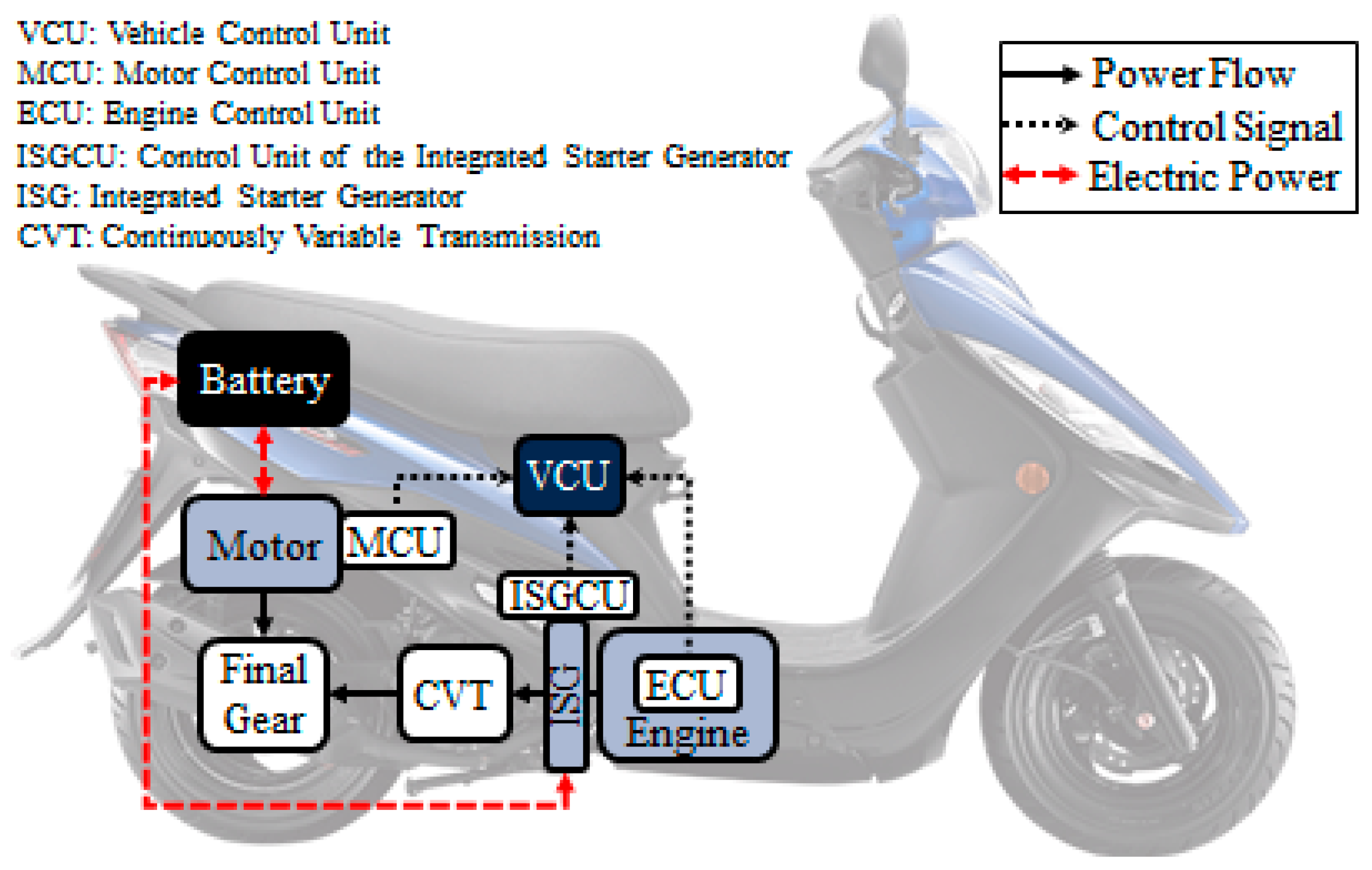
The schematic configuration of the hybrid electric motorcycle with three power sources in this study is shown in
Figure 1. The basic specifications of the drivetrain, engine, and ISG were mainly based on a commercially available motorcycle called the Honda PCX Hybrid. Moreover, a 48-V driving motor, a lithium-ion battery, a continuously variable transmission (CVT), and a final drive were included. The control strategy was formulated to optimize the power distribution among three power sources based on instant data of minimum equivalent fuel consumption. The main specifications of the test motorcycle are listed in
Table 1.
The test motorcycle was a type of parallel hybrid. The engine was coaxially coupled with the ISG. The ISG was placed between the engine and CVT. The driving motor was mechanically coupled to the final drive gear and the output shaft of the CVT. Finally, the final drive was directly linked to the rear wheel for propulsion. The simulation procedure of the test drive is stated below. The control model tracked the instant driving pattern. This information was imported into the control model of energy management to evaluate it with respect to the instant condition of power distribution. Then, a demanded vehicle speed for the simulation platform was generated and compared with the actual vehicle speed simulated from the vehicle dynamic model. The resulting error of driving speed was transmitted to the driver model where the instant throttle opening and braking torque were calculated based on proportional integral (PI) control. Then, this evaluated torque command was transferred to the energy management system where an appropriate distribution ratio of torque outputs was computed with reference to the instant state of charge (SOC) of the battery and the torque constraints of power source. These evaluated torque commands were sent to the three models of power source. Then, the actual vehicle speed at the next time step could be calculated via the motorcycle dynamics model.
2.1. Driving Cycle Model
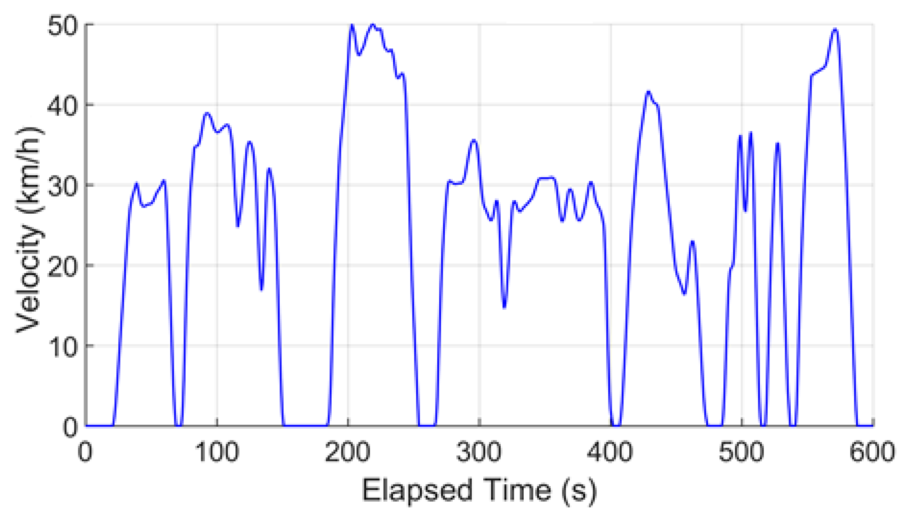
The motorcycle density in Taiwan is now the highest in Asia. Even though motorcycles are smaller than cars, their total emissions of pollutants are relatively higher. All the newly produced motorcycles are required to be tested for the emission of pollutants under the specific driving cycle, and they can only be put onto the market when the test is passed. In order to simulate the performance and energy consumption of the test motorcycle when actual driving on roads, the world motorcycle test cycle (WMTC), in compliance with the Stage 6 Gasoline Vehicle Emissions Standards in Taiwan, was utilized, as shown in
Figure 2. According to the testing regulations of Taiwan driving cycles in WMTC Class 1, this research focused on engine displacement < 150 cc and maximal speed < 100 km/h, referring to urban driving. The total driving time and maximum driving speed for WMTC were 600 s and 50 km/h, respectively.
2.2. Driver Model
The driver model in the simulation platform was used to simulate the driver’s control and operational response for the accelerator and brake. The actual vehicle speed and demanded vehicle speed plus the difference between them calculated from the simulation platform were input into the driver model and converted to the required throttle opening and brake torque as outputs via the PI controller for modulating the vehicle dynamics at the next instant.
2.3. Engine Model
The specifications of the internal combustion engine model in this study were adopted from the original design data of the Honda PCX Hybrid and, accordingly, the brake specific fuel consumption (BSFC) in terms of engine torque and rotational speed was constructed. Then, the required torque output of the engine plus that of the ISG due to the coaxial coupling between the engine and ISG was sent to the CVT model.
2.4. Motor and ISG Model
The type of motor used for the motor and ISG models was a brushless DC motor. The torque commands of the motor and ISG were sent from the energy management system to the motor and ISG models where the appropriate torque for propulsion was evaluated by considering the maximum physical constraint for protection. The corresponding efficiencies of the motor and ISG can be calculated through two-dimensional (2D) look-up tables in terms of input torque and rotational speed as shown below.
where
is the efficiency of the motor,
is the torque of the motor,
is the rotational speed of the motor,
is the efficiency of the ISG,
is the torque of the ISG, and
is the rotational speed of the ISG.
2.5. Lithium-Ion Battery Model
A lithium-ion battery was used to provide the electric energy to the driving motor and ISG. The relationships between internal resistance and voltage were obtained from the experimental data, allowing the SOC of the battery to be estimated. Since the precision of estimating the SOC affects the vehicle dynamics and strategy of energy management, an internal resistance model was adopted. Accordingly, the equivalent internal resistance of battery was expressed in terms of
SOC and temperature, as shown below.
where
SOC is in a range of 0–1 (0%–100%). The formula to calculate
SOC is described as
where
is the initial state of charge of the battery,
is the nominal capacity of the battery,
is the discharging current of the battery,
is the current flowing to the motor, and ISG is calculated based on the following expression:
where
is the open-circuit voltage of the battery that is a function of SOC and
, i.e.,
, and determined by a look-up table from experimental data;
is the power of the motor or ISG. Then, the voltage of the battery under charge/discharge loading,
, can be calculated as follows:
2.6. CVT Model
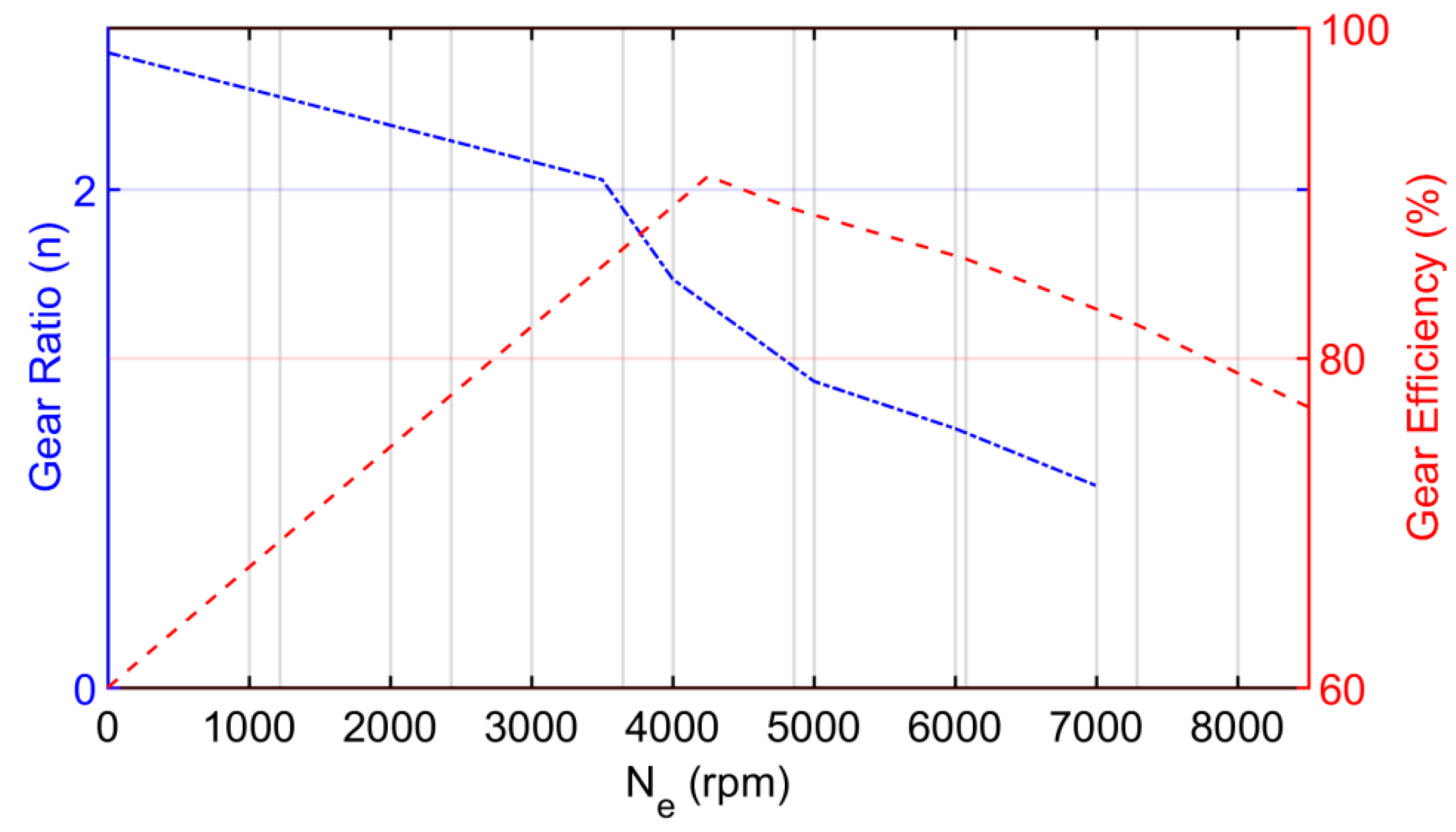
The CVT model was used to calculate the required torque and rotational speed of the engine coupled with the ISG via the CVT transmission system. The output torque and rotational speed of the CVT were related to those of the wheel,
and
, through the final drive with a final speed reduction ratio. According to the original data of the Honda PCX Hybrid, two one-dimensional (1D) lookup tables of the gear ratio and gear efficiency versus the engine speed were constructed, as shown in
Figure 3.
2.7. Motorcycle Dynamics Model
Considering the various types of resistance in driving, the wheel driving force is mainly the sum of air resistance, rolling resistance, grade resistance, braking force, and inertia resistance. Based on this mathematics model of dynamics, the rotational speed of wheel and vehicle speed at every instant could be calculated, serving as feedback to the CVT model and driver model for correcting the instantaneous motion of the motorcycle. Accordingly, the acceleration of the motorcycle in terms of the various forces and resistances mentioned above can be written as
where
is the gross vehicle mass, i.e., the sum of vehicle mass and driver mass,
is the torque of the drivetrain,
is the tire radius,
is the total efficiency of the drivetrain,
is the coefficient of rolling resistance,
is the acceleration of gravity,
is the coefficient of air drag,
is the frontal area of motorcycle,
is air density,
is the braking force,
is the vehicle speed, and
is the inclined angle.
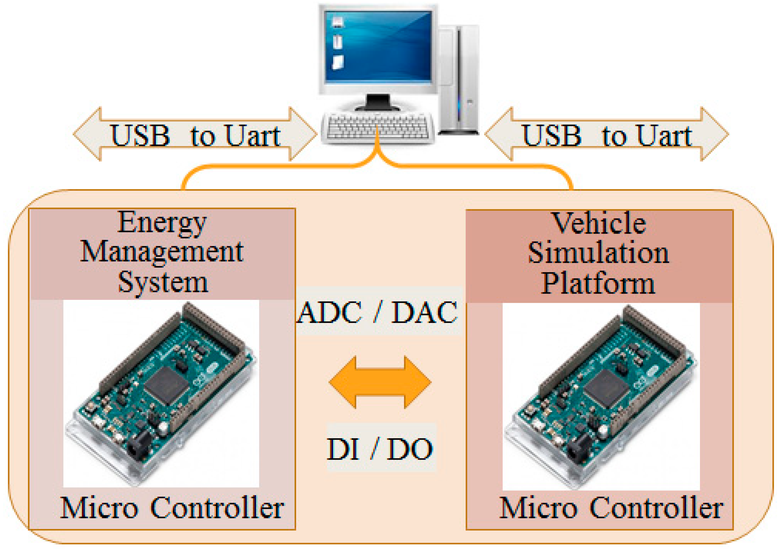
2.8. HIL Architecture
In this study, the HIL system of HEV consisted of two real-time Arduino DUE controllers, as shown in
Figure 4. One served as the embedded system of the vehicle called the energy management system, and the other acted as the vehicle simulation platform comprising the driving cycle, driver, motor, ISG, engine, lithium-ion battery, CVT, and motorcycle dynamics models. A transit circuit of UART to USB was required for the computer to communicate with the Arduino controllers through the interface pin locations named UART, SPI, andI2C. Furthermore, the Simulink Support Package for Arduino Hardware in Matlab/Simulink® (2017a, MathWorks, Natick, MA, USA) was utilized to connect with the HIL system so that a real-time simulation model could be built.
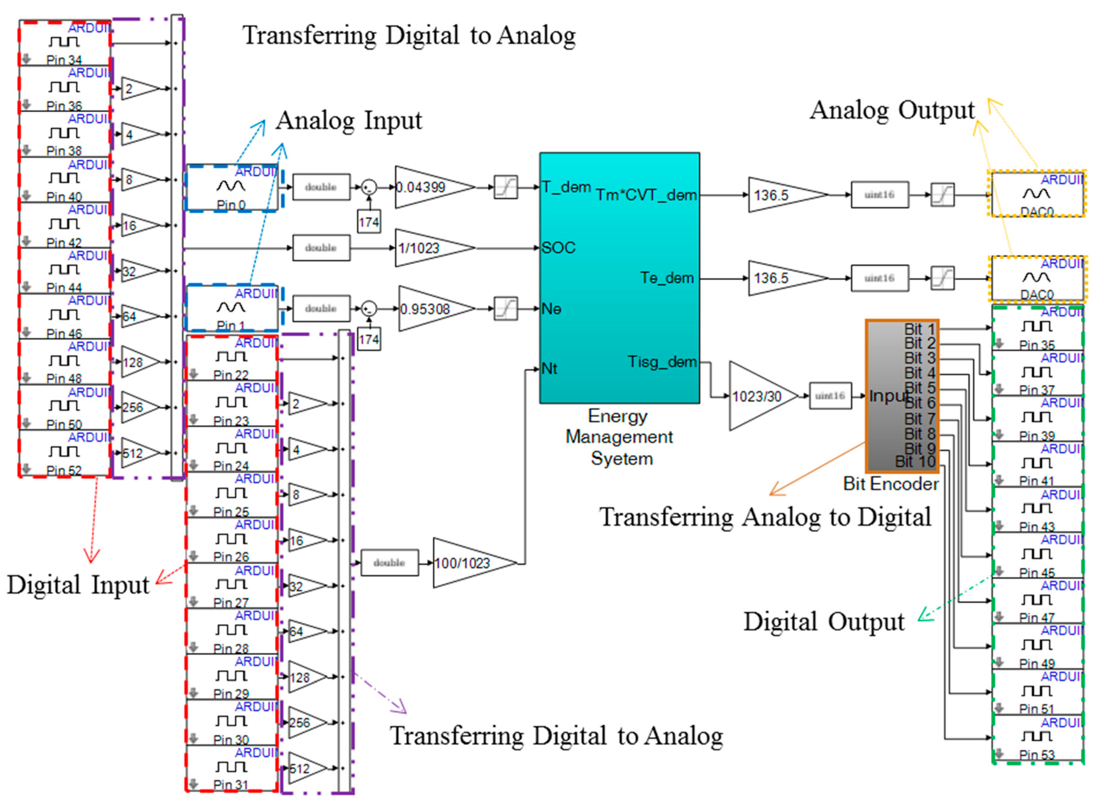
The schematic diagrams of the input/output interface between two real-time controllers and the software structure for the energy management system controller are illustrated in
Figure 5 and
Figure 6, respectively. To manage the insufficient analog outputs of the microcontroller, the digital outputs were combined with analog signals as shown in
Figure 5 and
Figure 6. By using the signal scale transform, the resolution of the analog signal was maximized. Furthermore, for the digital-to-analog transformation, values 0–4095 represent 0.56–2.76 V of output voltage. Therefore, the initial value needed to be compensated for the signal inverse as best as possible. The simulation process is briefly described below. Initially, the information of actual and demanded speeds of the vehicle were taken from the driving cycle model and transmitted to the driver model. Then, the demanded torque of vehicle,
, was calculated based on PI control. In addition, the SOC was evaluated via the lithium-ion battery model, and the rotational speed of the engine, as well as the ISG,
, was determined through the CVT model. These three variables, i.e.,
, SOC, and
, were converted to voltage signals as shown in the input interface of
Figure 5 and then directed to the receiving port of the controller of the energy management system as shown in
Figure 6. Based on these input data, the demanded torques of the engine, motor, and ISG, as well as the switching mode, were evaluated via the energy management system model and transmitted through the transmitting port shown in
Figure 6 back to the output interface of
Figure 5. During the simulation, the processed variables were constantly switched between digital values and voltage signals back and forth.
3. Energy Management System
RBC and ECMS were used to develop the control strategies for the energy management system capable of optimization in favor of fuel economy. Furthermore, the physical characteristics of the related vehicle dynamics were built into mathematical models. By combining these models and strategies, various simulation cases could be performed. In consequence, the favored results of maximum energy efficiency accompanied by the optimized strategy could be attained.
3.1. RBC Method
In this study, the RBC method was utilized to establish the decision-making algorithms for driving torque distribution of three power sources for a hybrid electric motorcycle. Initially, the demanded torque of the vehicle was calculated from the energy management system through PI control, while was evaluated in the lithium-ion battery model. Furthermore, , which is equal to the rotational speed of ISG due to their coaxial coupling, was obtained, while was determined via the CVT model based on a parallel configuration. Then, based on these three inputs of rotational speed, an appropriate set of driving torque distribution of three power sources was calculated through three 1D lookup tables along with the related power limitations and physical constraints. Accordingly, the demanded torques of the motor, engine, and ISG (, , and ), as well as the operation mode (Mode), were determined based on the control strategy of the energy management system.
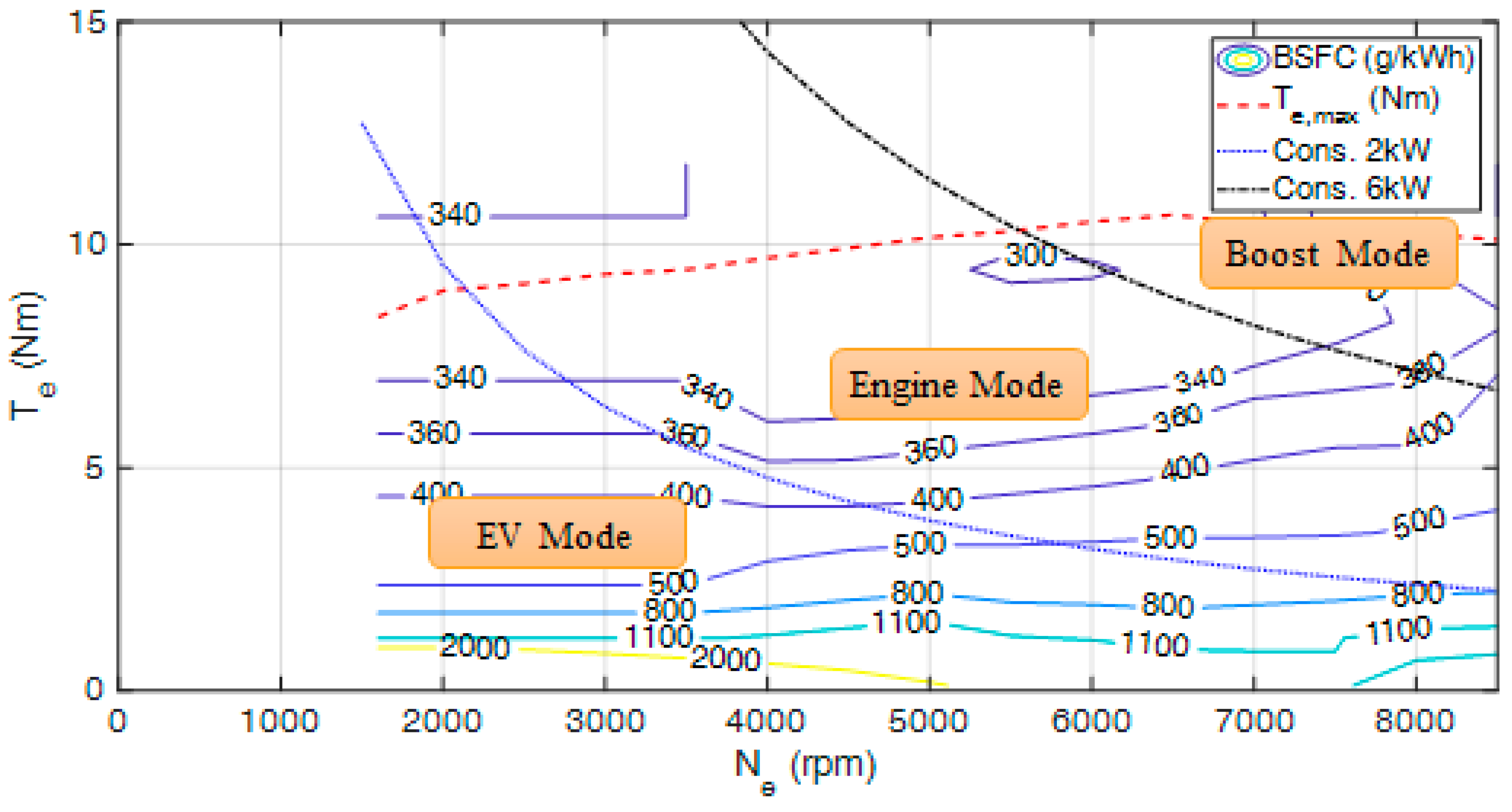
The RBC method is briefly described below. Three driving modes were formed by two torque constraints as shown in the performance map of the engine in
Figure 7. The blue line and black line in
Figure 7 indicate the torque constraints of 2 kW and 6 kW, defined as “low power” and “high power”, respectively. Then, the lower-left region of the blue line is designated as the purely electric drive mode, and the region between the blue and black lines is defined as the purely engine-driven mode, while the upper-right area of the black line is set as the fully hybrid drive mode. The corresponding operational conditions are described in
Table 2. The RBC strategy was based on the engine characteristics. The efficient BSFC area was chosen to be used to modify the engine output. A lower BSFC value would result in a higher engine efficiency. Therefore, from
Figure 7, the low-load area was avoided to raise the average engine efficiency.
When the demanded torque of the driver (T_dem) is zero, the motorcycle is operated in the system ready mode where the demanded torques of the engine, motor, and ISG are all set to be zero. When the demanded torque of driver is greater than 0.2 Nm, the operation is switched to the purely electric drive mode, i.e., the EV mode. In this mode, if T_dem exceeds the limit of maximum engine torque (T
e,max) indicated by the red dotted line in
Figure 7, the motor and ISG simultaneously deliver driving torque in a ratio of 7:3; otherwise, the ratio is 8:2. When T_dem lies between the low-power and high-power lines, or the instant SOC is too low to sustain the supply of electricity for the motor and ISG, the operation is then changed to purely engine-driven mode, i.e., engine mode. In this mode, if T_dem is greater than T
e,max, the deficiency of engine torque is supplemented with the assistance of the motor. The output torques of the engine and motor are in a ratio of 7:3. Otherwise, the demanded torque is totally supported by the engine. Now, if T_dem is beyond the high-power limit, the operation enters into boost mode. In this mode, the genset mode is activated at SOC < 0.2, while the safety mode is on if both T_dem = 0 and SOC = 0.
3.2. ECMS Method
The power ratio (PR) was determined based on the ECMS that converts the variation of SOC into an equivalent expression of fuel consumption. Therefore, the algorithm flow was constructed as follows:
By constructing the performance models of the powertrain, defining the corresponding objective function, and planning a global search for optimization, the minimum solutions of equivalent fuel consumption with the optimal results of the power ratio of engine (
) and power ratio of motor (
) were then obtained. Then, the multi-dimensional table was constructed and implemented into the controller of energy management system for optimization. The power ratios of the three power sources are expressed below.
where
is the total demanded torque,
is the demanded torque of the engine,
is the demanded torque of the ISG, and
is the demanded torque multiplied through the CVT.
The test data of the engine from the Honda PCX Hybrid motorcycle, ISG, and 48-V motor coupled with physical constraints were uploaded into the program in the form of 1D or 2D look-up tables. The tables of test data included the open-circuit voltage of battery vs. the SOC, the charge/discharge efficiency of the battery vs. the SOC and current, the charge/discharge efficiency of the motor vs. the torque and rotational speed, the BSFC of the engine vs. torque and rotational speed, and the efficiency of the ISG vs. torque and rotational speed; those of the physical constraint contained the maximum output torque of the engine vs. rotational speed, the maximum output torque of the motor vs. rotational speed, the maximum output current of the motor vs. torque and rotational speed, the maximum output torque of the ISG vs. rotational speed, the maximum output current of the ISG vs. torque and rotational speed, etc. All the quantized data mentioned above were loaded into the program so as to proceed with the optimization algorithm.
The global search of optimal solutions based on ECMS was executed by six for loops with respect to the discretized SOC, demanded torques, rotational speeds of the engine and motor, etc. The various operating modes were judged through conditional statements of “if–then–else” in the program. Then, required variables such as the BSFC of the engine, efficiencies of the motor and ISG, demanded torques of the engine and motor, etc. could be calculated. After that, the results of equivalent fuel consumption based on the ECMS under various conditions could be obtained and stored in a four-dimensional (4D) matrix named mf_total_boost. Therefore, the minimum equivalent fuel consumptions under various engine torques with respect to the specific SOC, rotational speed, and demanded torque could be attained and, accordingly, the optimal power ratios could be derived.
For the purpose of simplifying the algorithm of the control model so as to satisfy the heavy loads on real-time calculation for logical control in the embedded systems, the analytical procedures for determining the optimal power ratios were constructed using some key parameters among the models, such as the BSFC, efficiencies of the motor and ISG, maximum torque constraints of the three power sources, and battery parameters. Then, the optimal solutions of the power ratios with respect to the discretized input parameters, i.e., SOC, demanded torques, and rotational speeds of the engine and motor, were obtained using the global search for the minimum objective function based on the ECMS algorithm, as shown below.
where
is the optimal objective function,
is the actual consumption rate of fuel mass for the engine,
is the factor as a function of the
SOC,
is the equivalent consumption of fuel mass for the motor,
is the equivalent consumption of fuel mass for the ISG, and
is the mathematical term indicating the relationship between
SOC and the penalty value. Moreover,
can be written as
where
is the average value of
,
is the efficiency of the battery, and
is the power of the motor. Similarly,
is described below.
where
is the power of the ISG.
By substituting Equations (14) and (15) into Equation (13),
becomes
When a searching point exceeds the specific physical constraints, a penalty value with an extremely large number is assigned to
; otherwise, a normal value of zero is replaced instead, as seen below.
The schematic diagram of the global search for the optimal energy management is shown in
Figure 8. The main target was to search for optimal operating points with respect to the minimum
by computing the fuel consumption of the engine and total consumption of electric energy, along with the equivalent fuel consumption of the motor and ISG under the discretized variables of demanded torque, SOC, rotational speeds of the engine and motor, and power ratios of the engine and motor. A final optimal 4D table of distribution could be obtained by way of performing double interpolation for minimization twice, as expressed below.
This optimized 4D parametric table was integrated with operation modes to form a multi-dimensional table for optimal control and supervising the fuel economy of the entire system. This considerably reduced the loading for real-time computation and desirably fulfilled the requirement for real-time control of the embedded systems.
5. Conclusions
In this study, a simulation platform for a hybrid electric motorcycle with three power sources of engine, driving motor, and ISG was proposed. This platform comprised the driving cycle, driver, lithium-ion battery, continuously variable transmission (CVT), motorcycle dynamics, and energy management system models. Furthermore, a hardware-in-the-loop simulation was performed using TWO Arduino DUE microcontrollers coupled with the required circuit to process analog-to-digital signal conversion for the input and output. The WMTC driving cycle was used for evaluating the performance characteristics and response relationship among subsystems. Control strategies used for optimization were the pure engine, RBC, and ECMS. As a result, the improvement percentages of equivalent fuel consumption and energy consumption for RBC and ECMS compared with the pure engine mode using the pure software simulation were 17.74%/18.50% and 42.77%/44.22%, respectively, while those with the HIL were 18.16%/18.82% and 42.73%/44.10%, respectively.
ECMS is a global optimal search method that searches for the optimal solution based on the system parameters and physical characteristics. The ECMS optimal results can be calculated offline in the form of a multi-dimensional matrix which is downloaded to the microcontroller of the HIL environment. Due to the significant reduction in computational load of the matrix compared to other optimal algorithms, the ECMS has strong advantages in terms of computational loading and computational time. This research successfully transformed the analog-to-digital or digital-to-analog signals without signal distortion as best as possible. At the same sampling time, the results showed that the ECMS can be practically applied with microcontrollers. Compared to the previous HIL system with a more complicated structure and expensive resources, this novel structure can be directly employed on the three-power-source hybrid motorcycles. In future development, the optimization of the microcontroller on the vehicle simulation platform is expected to enhance the accuracy and stability of signal processing so as to realize practical implementation into actual vehicles, greatly contributing to energy saving and environmental protection.


