Article

Harvesting Energy from Planetary Gear Using Piezoelectric Material

by
Haider Jaafar Chilabi
1,2,
Hanim Salleh
3,
Eris E. Supeni
1,*,
Azizan As’arry
1,
Khairil Anas Md Rezali
1 and
Ahmed B. Atrah
4
1
Department of Mechanical and Manufacturing, Faculty of Engineering, Universiti Putra Malaysia, Serdang, Selangor 43400, Malaysia
2
Midland Refineries Company (MRC), Ministry of Oil, Republic of Iraq, Baghdad 10022, Iraq
3
Institute of Sustainable Energy, Universiti Tenaga Nasional, Jalan IKRAM-UNITEN, Kajang, Selangor 43000, Malaysia
4
Directorate General of Electrical Transmission Projects (ETP), Ministry of Electricity, Baghdad 10001, Iraq
*
Author to whom correspondence should be addressed.
Energies 2020, 13(1), 223; https://doi.org/10.3390/en13010223
Submission received: 16 October 2019 / Revised: 8 November 2019 / Accepted: 15 November 2019 / Published: 2 January 2020

Abstract

:
In the present study, a rotational piezoelectric (PZT) energy harvester has been designed, fabricated and tested. The design can enhance output power by frequency up-conversion and provide the desired output power range from a fixed input rotational speed by increasing the interchangeable planet cover numbers which is the novelty of this work. The prototype ability to harvest energy has been evaluated with four experiments, which determine the effect of rotational speed, interchangeable planet cover numbers, the distance between PZTs, and PZTs numbers. Increasing rotational speed shows that it can increase output power. However, increasing planet cover numbers can increase the output power without the need to increase speed or any excitation element. With the usage of one, two, and four planet cover numbers, the prototype is able to harvest output power of 0.414 mW, 0.672 mW, and 1.566 mW, respectively, at 50 kΩ with 1500 rpm, and 6.25 Hz bending frequency of the PZT. Moreover, when three cantilevers are used with 35 kΩ loads, the output power is 6.007 mW, and the power density of piezoelectric material is 9.59 mW/cm3. It was concluded that the model could work for frequency up-conversion and provide the desired output power range from a fixed input rotational speed and may result in a longer lifetime of the PZT.

1. Introduction

Converting mechanical energy such as kinetic energy, vibration or distortion energy into electrical energy is known as energy harvesting. The fast development of wireless sensor networks (WSNs) and the solution of storage power better efficacy will, ultimately, increase the devices that use self-power in an automotive application, monitoring of the environment, and health-care [1]. However, the limitation of the power source of WSNs is one of the significant problems in this technology. Further, there are issues such as volume, weight, and short lifetime of batteries, which is much shorter than the WSN life, and batteries must be changed frequently. Consequently, researchers must find an alternative power source by focusing more attention on energy-harvesting technology [2,3].
An energy harvester for powering WSNs and microdevices is a feasible approach in our environment, due to its low power consumption, small size, and special working environment. Piezoelectric energy harvesting is one of the novel approaches that has been developed to harvest power for these devices using different types of mechanical sources [4]. Depending on the application, different types of harvesting energies, as well as the handiness of the mechanical power sources, are available most of the time. Mechanical energies such as airflow, vibration, pressing, rotational machine, and human motion are variable frequencies and amplitude energies, which can be called random energies that are available everywhere [5].
Rotational mechanical energy is one of the important power sources for piezoelectric energy harvesting. Different types of rotational power sources have been used in the past decades for piezoelectric energy harvestings, such as rotational machines [6,7,8,9,10], human motion [11,12], vehicle tires [13,14,15,16,17], and even air, wind and fluids [18,19,20,21,22,23,24]. They have been applied in different applications such as WSNs in any rotary machine [8,25], tire pressure-monitoring systems (TPMSs) [26,27,28], wearable devices, and medical implants [29,30,31,32].
The principle of rotational piezoelectric energy harvesting operation is based on the PZT plucking for excitation, which results in PZT bending, vibration, or pressing, and thus voltage is generated. Researchers have used different excitation elements in rotational piezoelectric energy harvestings, such as mass [28,31], magnetic [33,34,35] centrifugal force [36,37], gravitational force [38,39,40], and gear teeth force [41,42] or a compilation of these elements [26,43,44]. They have also applied these elements to widen the broadband range [14,45,46] or for frequency up-conversion [6,43,47] and rotational frequency, which is considered to be low in some cases compared to piezoelectric resonant frequency. While these different methods for rotational piezoelectric energy harvesting offer many advantages, they have numerous challenges. These include harvesting the desired output power ranges from a fixed input rotational speed, finding new methods in frequency up-conversion with better results, less force on PZT and hence a longer lifetime, and avoiding using slip ring or any other extra device for power transfer. Using a new source power type, design or method that can achieve these challenges is still desirable.
Most of the previously published papers on rotational piezoelectric energy harvesting area focused on frequency up conversion; however, frequency up conversion methods continues to be enhanced. Hence, rotational power sources, especially for wind, human motion, some rotary machines, and some vehicle tires, are generally considered as low frequencies, compared to PZT frequency. In some cases, the wiring for output power transfer is still an issue because the PZT is rotating with the system and thus a slip ring or any other wireless transfer is needed, which makes the device more complicated [2,25,27,48,49,50]. Also, the heavy and rapid repetitive bending or striking on the PZT with the direct excitation contact can be considered an issue because it will reduce its lifetime; however, this can be avoided in different ways [35].
Using a gear as a rotational mechanical input for piezoelectric energy harvesting excitation has been considered a good and new method. Only a few works have been accomplished using the gear as input in rotational piezoelectric energy harvesting. Juil Park et al. [41] proposed a design where the cantilever free tip was excited by any rotary motion of mechanical devices. Using a mouse gear as the rotary mechanical device, the frequency can be changed from 0 to 800 Hz according to the changes in rotational speed and gear teeth numbers. Further, the output voltage and power generated from the gear model frequency up-converted kinetic energy harvesting device have reached a level of interest for practical applications and could be easily increased using multiple cantilevers within a single gear [51]. Energy harvesting is produced from an impact by using a piezoelectric Micro-Electro-Mechanical Systems (MEMS) scavenger. Useful electrical power is generated by the impact of the rotating gear on the MEMS piezoelectric transducer [52]. Moreover, Janphuang et al. [53] conducted an experiment where the results revealed that free vibrations of the harvester after plucking contributed significantly to the power efficiency. The efficiency and output energy can be greatly improved by adding a proof mass to the harvester. Yang et al. [54] proposed a gullwing-structural piezoelectric energy harvester that consists of two typical non-linear buckled-bridges to scavenge low-frequency rotational energy based on a gear mechanism induced oscillation. This design is promising for self-powered sensors, especially at changeable and low frequency, such as tire pressure monitoring. However, as far as the authors are concerned, no research has been done using the planetary gear. Also, the PZT lifetime, wiring, and getting the desired output power from a fixed input rotational speed have not been clearly studied.
The novelty of this work is to design, fabricate, and test a compact frequency up-conversion energy harvester that can harvest sustainable energy in broad range frequencies. This work is inspired from previous studies (that use normal gear), but with an enhanced gear design (planetary gear), which has less effect on the PZT and its primary system. The planetary gear design can harvest energy using a piezoelectric cantilever. The advantage of this study design over the previous designs that use a standard gear [41,51,52,55] is that it uses interchangeable planet covers so that it will have the ability to provide the desired output power range from a fixed input rotational speed, thus, by increasing the planet cover numbers without the need to increase the input speed, use of multiple PZT cantilevers, or increase the PZT pressing force. Moreover, it could be applied in any rotational machine such as a steam turbine with a pump for powering WSNs. Also, the PZT will be gently bent by the pressing of planet teeth gear, due to the way the planet gear moves in the planetary gear system, and this may result in a longer life-time for PZT. The wiring will not be an issue; there is no need for a slip ring or any other wireless device to transfer output power because the PZT will be fixed and will not rotate with the system.
Many applications can be suggested to apply this piezoelectric energy harvester prototype due to its properties, such as when it is connected to any rotational source that runs with variable speeds such as steam turbine or wind rotational source; moreover, it could be used in human motion energy harvesting with a more compact design.

2. Theory and Analytical Equation

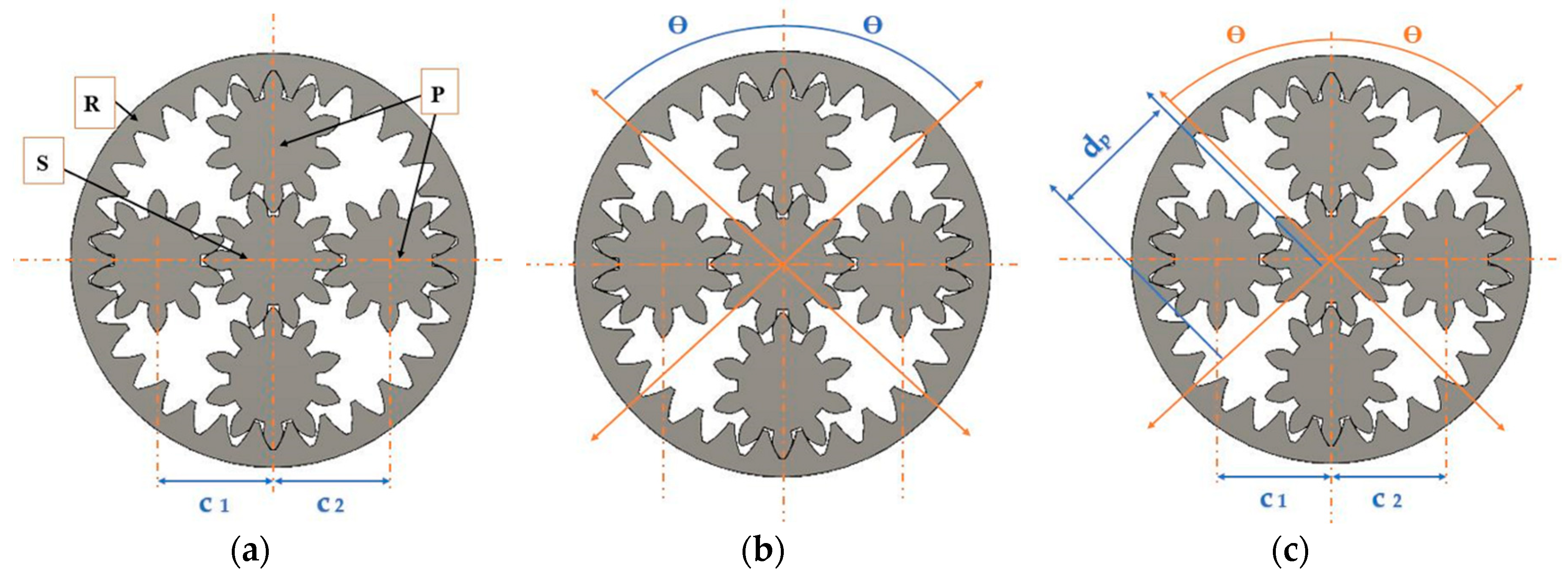
2.1. Planetary Gear System

The planetary gear is a unique gear system that offers features such as a compact size and speeds variation. Planetary gear contains four core parts: ring gear, sun gear, planet gears, and the carrier that connects the planet gears. Calculating the planetary gear ratio may look daunting; however, the system single-axis nature will make it easy.

2.1.1. Gear Relationship in the Planetary Gear System

To determine teeth numbers and arrange them based on the sun gear, planet gear, and ring gear, three conditions must be satisfied by these parameters as follows [56,57]:
The 1st condition is given by Equation (1):
Nr = Ns + 2 Np,
where Nr, Ns, and Np are the number of teeth for the ring gear, sun gear, and planet gear, respectively. This condition is important for matching the gear center distances. Since this condition works for a standard gear system, varying the teeth number is possible using the design of a shifted gear. To use the profile of the shifted gear design, it is important that the center distance between the sun and the planet gears (c1) matches the other center distance (c2), where c1 = c2.
The 2nd condition is given by Equation (2):
(Ns + Nr) n = Integer,
This condition is important to ensure equal spacing of planets gears around the sun gear. Further, if it is required for uneven planet gear placement, then Equation (3) can be used:
(Ns + Nr) θ/180 = Integer
where θ is half of the angle between the adjacent planet gears.
The 3rd condition is given by Equation (4):
Np + 2 < (Ns + Np) sin (180/n),
This condition is important to make sure that the adjacent planet gears can run with no interference between each other. Moreover, this is for a standard gear design that has even planet gear placement, whereas for other cases, the system should follow Equation (5):
dp< 2c1 sin θ,
where dp: planet gear tip diameter, c1: sun and planet gear central distance. Figure 1 shows the diagram of the three conditions.

2.1.2. Transmission Ratio of the Planetary Gear System

The simple planetary gear set overall ratio can be calculated using Equations (6) and (7) [58], which represent the interactions of sun planet and planet-ring, respectively:
Ns ωs + Np ωp − (Ns + Np) ωc = 0,
Nr ωr − Np ωp − (Nr − Np) ωc = 0,
where ωs, ωp, ωc, ωr are the angular velocities of the sun gear, planet gears, planet carrier, and ring gear, respectively, and Ns, Np, Nc, Nr are the number of teeth r for the sun, planet, carrier, and ring gear, respectively. From this, Equations (8) and (9) can be deduced;
Ns ωs + Nr ωr = (Ns + Nr) ωc or,
(Nr/Ns) = (ωc − ωs)/(ωr − ωc),
Considering ωr not equal to ωc.
The rotation direction and the ratio of transmission in the planetary gear system would change according to which gear is the input and output, and which gear is fixed. This type is the planetary type, which is the same as the case of the proposed study; the ring gear is held fixed (R), the sun gear (S) will be the input, and the carrier (C) will be the output, and transmission ratio can be found by Equation (10).
Transmission ratio = (1 + Ns/Nr)/Ns/Nr = (Np/Ns) + 1,
Note that the directions of rotation of input and output axes are the same, for example: Ns = 10, Np = 10, Nr = 30; then, the transmission ratio = 4, and this means that the speed of the output (carrier) that affects PZT is ¼ the input speed, which is the sun gear speed.

2.2. Piezoelectric Theory

The description of the piezoelectric effect can be shown by the coupled equations [59,60,61], and as in Equations (11) and (12):
S = sE · T + dt · E,
D = d · T + εT · E,
Here, T, S, E, and D are mechanical stress, mechanical strain, electric field, and electric displacement (density of charge), respectively. Then, εT, and sE, are the permittivity of dielectric under a stress of zero or constant (which is indicated by superscript T) and compliance under an electric field of a zero or constant (which is indicated by superscript E). Further, d and dt are the piezoelectric direct and reverse effect matrices, where the superscript t is the transposed matrix. Thus, Equation (11) describes the piezoelectric reverse effect, and Equation (12) describes the direct piezoelectric effect.
The piezoelectric harvester design configurations are as follows. Since this study is mainly about piezoelectric materials that are used in energy harvesting with planetary gears, the following description mainly concerns piezoelectric material such as the sensor case, not the actuator. There are three operation modes in piezoelectric material: d15, d33, and d31, of which d15 is mostly not suitable to be used in energy harvesting because its relation is based on shear stress. Figure 2a,b show the two modes, d33 and d31, which are generally used in piezoelectric materials. Each number after d indicates some details. The first one (3) means that the voltage is generated along the z-axis, and this is for both modes. The second number is an indication of the direction of the applied force. This means that in the d33 mode, the stress effect and generated voltage are in the same direction (z-axis), while in the d31 mode, which is adopted in this study, the force is applied along the x-axis [61,62].
For the d31 mode, the Equations (11) and (12) can be written as in Equations (13) and (14):
S1 = sE11 · T1 + d31 · E3,
D3 = d31 · T1 + εT 33 · E3,
The d31 mode is commonly used for energy harvesters, e.g., for bimorphs, where two piezoelectric layers are attached, as shown in Figure 2. When the connection is in series, the two layers will be poled in the opposite direction, as presented in Figure 2c. Therefore, when compared to one layer, the current will be the same, the capacitance is half, and the voltage will be doubled. Figure 2d shows the parallel connection, which is used in this study, and it is more favorable because there will be a doubling of capacitance and current while the voltage is the same. However, the types of layer connections are affected only by the current to voltage ratio, not the output power [41,61].

3. Materials and Methods

In this study, a prototype planetary gear has been developed to evaluate its ability to function as a rotational piezoelectric energy harvester.

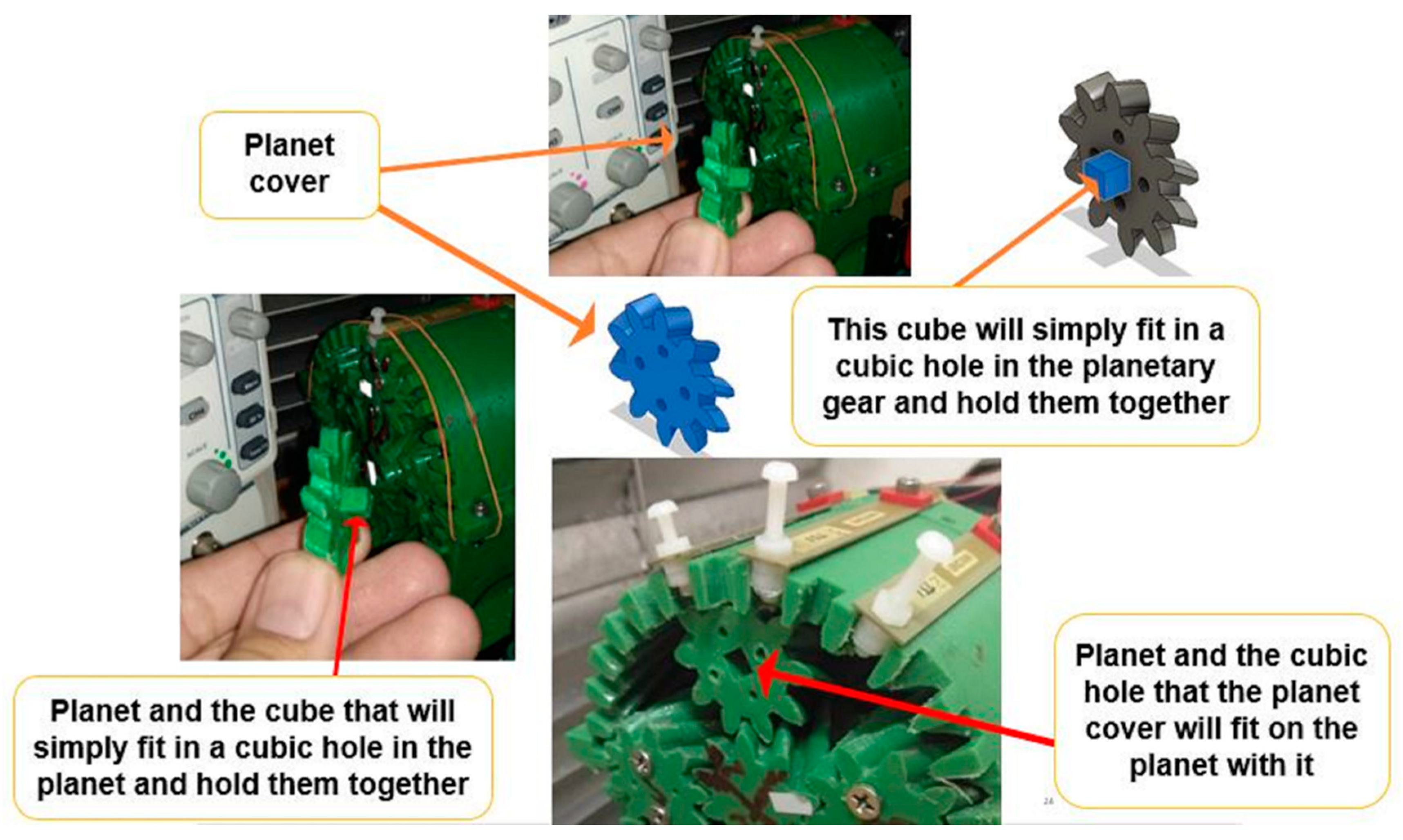
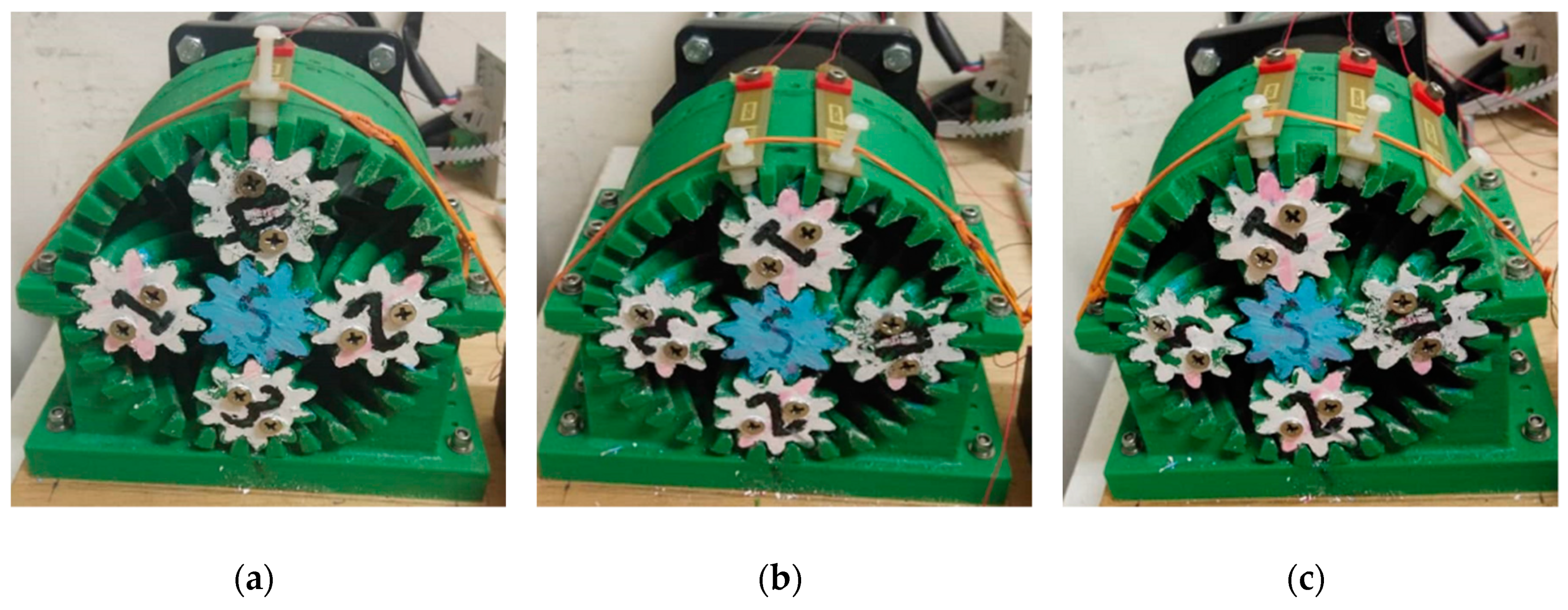
3.1. Fabrication of the Prototype

The energy harvester, which is mainly a planetary gear, consists of 30 teeth ring gears and is held stationary, one sun gear with ten teeth, which has been considered as the input for rotation from the motor, and four planet gears as shown in Figure 3. Only four planet covers have been used to prove the concept of their effect on optimizing output power. The planetary gear is made of a plastic named acrylonitrile butadiene styrene (ABS) from polymaker.com and was chosen due to its durability and suitability for high-speed application. The planetary gear (and ring gear) is about 100 mm diameter and 71 mm depth (to match the piezoelectric cantilever length). The sun gear diameter is 33 mm, with a depth of 71 mm; each planet gear has a diameter of 33 mm, a depth of 66 mm, and its planet cover is 5 mm, with a total depth of 71 mm. The piezoelectric bending transducer named sealed PZT (S234-H5FR-1803XB) from piezo.com. is made from (Pb—lead, Zr—zirconium, Ti—titanium), and has different layers of copper and Fr4 to make it more sealed and to handle bending and striking. The PZT cantilever is about 71 mm long, 10.4 mm wide, and 0.84 mm thick, all with copper and Fr4 protection layers, while the two PZT material layer dimensions are 46.4 mm long, 6.8 mm wide, with a thickness of 0.25 mm.
As shown in Figure 3, the planet gear cover works as an excitation element for PZT. The PZT is fixed on the outer side of ring gear from one end, and a cylindrical tip is attached on the other end; its length will control how much PZT should be bent by the planet gear teeth pressing. The wiring is connected directly from each piezoelectric, and there is no need for a slip ring or any wireless device for power transfer. A circuit has been made for measuring maximum output power, which contains a bridged rectifier for AC-DC conversion, box resistance RS-500W to provide ranges of loads, and an oscilloscope GWINSTEK GDS-2047E for measuring voltage. Output power is obtained by dividing the voltage square over the resistance that is used from the resistance box. An AC oriental motor model was used to rotate the planetary gear at setting speed of 90 r/min to 1500 r/min, which was controlled by the digital speed controller. The fabrications of the planetary gear system have been done using an Ultimaker +2 machine 3D printer that is available in the UPM CAD/CAM laboratory. This machine can perform 3D printing for plastic with high resolution, smooth surfaces, and with high accuracy.

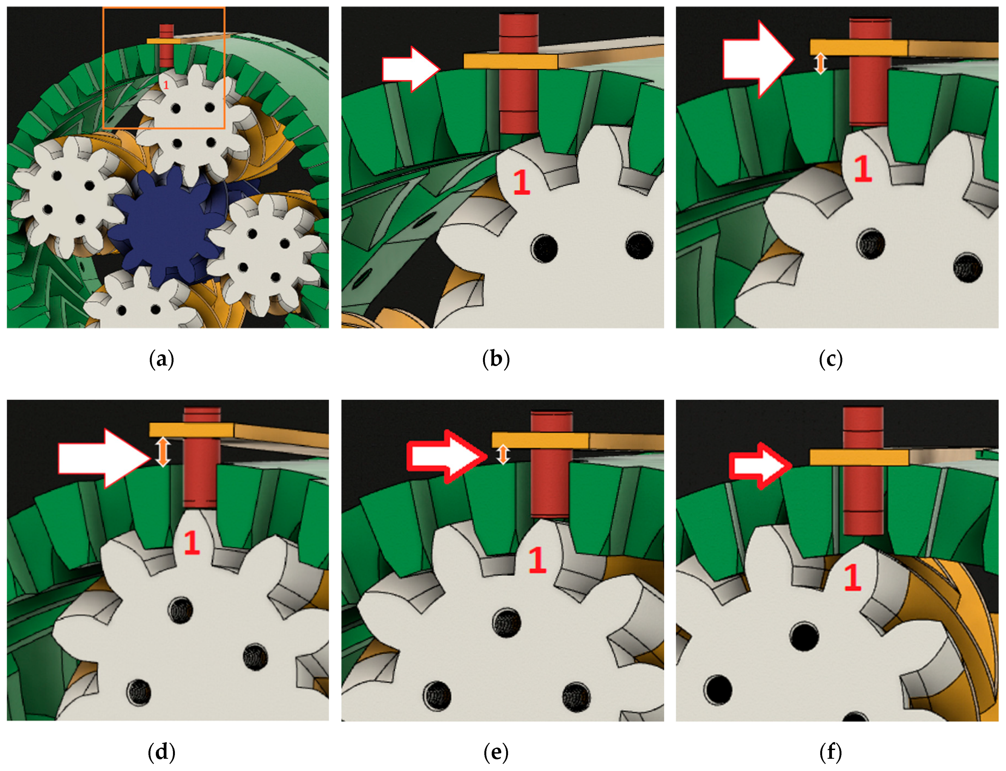
3.2. Experimental Setup and Procedures

Four experiments were conducted to evaluate the ability of the prototype to generate output power under field-simulated rotational machine conditions. Various effects, such as rotational speed, interchangeable planet cover numbers, different distances between PZTs and increasing PZT numbers have been tested with regard to the harvest output power to evaluate the prototype ability to harvest energy. PZT has been tuned by bending it with the planet teeth and the cylinder attached to it. The maximum piezoelectric amplitude is 10 mm, as stated by the manufacturers, but to ensure that the PZT will work for a long time without being damaged, 5 mm has been chosen as a distance displacement for maximum bending, Figure 4 below shows the PZT bending sequence.
Figure 4 describes the sequences of PZT smooth bending by the planet gear cover tooth named No. 1, and the arrow shows how much the PZT will be bend at each stage. According to the way the planet gear will move in the planetary gear system, the contact between gears and PZT will be smooth, and thus less tear and wear will occur. The different stages in Figure 4 can be illustrated as follows: (a) the whole prototype with tooth no. 1 that will bend the PZT, (b) the PZT before been bent by tooth no. 1, (c) the PZT when tooth no. 1 starts to bend it, (d) when tooth no. 1 fully bends it, (e) the PZT when tooth no. 1 starts to release it, and (f) the PZT after tooth no. 1 finishes bending it.
In order to ensure that the optimum power peak cannot be missed, the circuit external resistance (RL) must be equal to the prototype internal resistance (RS), defined as impedance matching, according to the maximum power transfer theorem [63,64]. Prototype internal resistance is calculated by Equation (15).
R S   =   1 / ( 2   ×   pi   ×   c   ×   f )
where c is the internal capacitance of the prototype which changes as the PZT number increases, and f is the bend per second (frequency). The theoretically calculated resistance is approximate; therefore, an experiment attempt has been made to measure the optimum resistance. A range of DC voltage with regard to different loads has been measured in order to obtain the optimum resistance. The voltage is measured for different values of resistances, and the power is calculated using Equation (16)
P = V2/RL,
where V is the voltage measured by the oscilloscope, and RL is the resistance from the resistance box.
The calculated power versus the values of resistance has been plotted for different rotational speeds and planet cover numbers to find the optimum resistance corresponding to maximum output power, and it is close to the theoretical value.
The electric circuit has been made to measure the output voltage, and it contains a bridge rectifier to change electricity from AC to DC and resistance from the resistance load box, which could supply several ranges of loads to the circuit. A commercial bridge rectifier has been used with an efficiency of 81.2%, as stated by the supplier. The experimental test shows that the bridge rectifier efficiency ranges from 62% to 75% at different rotational speeds and input loads. However, the efficiency of the rectifier at optimum resistance at different rotational speeds ranges from 70% to 73%. Figure 5 shows the circuit diagram which has been used for this experiment.

3.2.1. Effect of Rotational Speed

The first experiment discusses the rotational speed effect; the rotation speed affects the output voltage and thus, the output power. The rotational speed represents the frequency with which the PZT will be consequently bent. The motor digital speed controller controls these rotating speeds. To prove the concept of their effects, five rotational speeds are used: 300, 600, 900, 1200, and 1500 rpm.

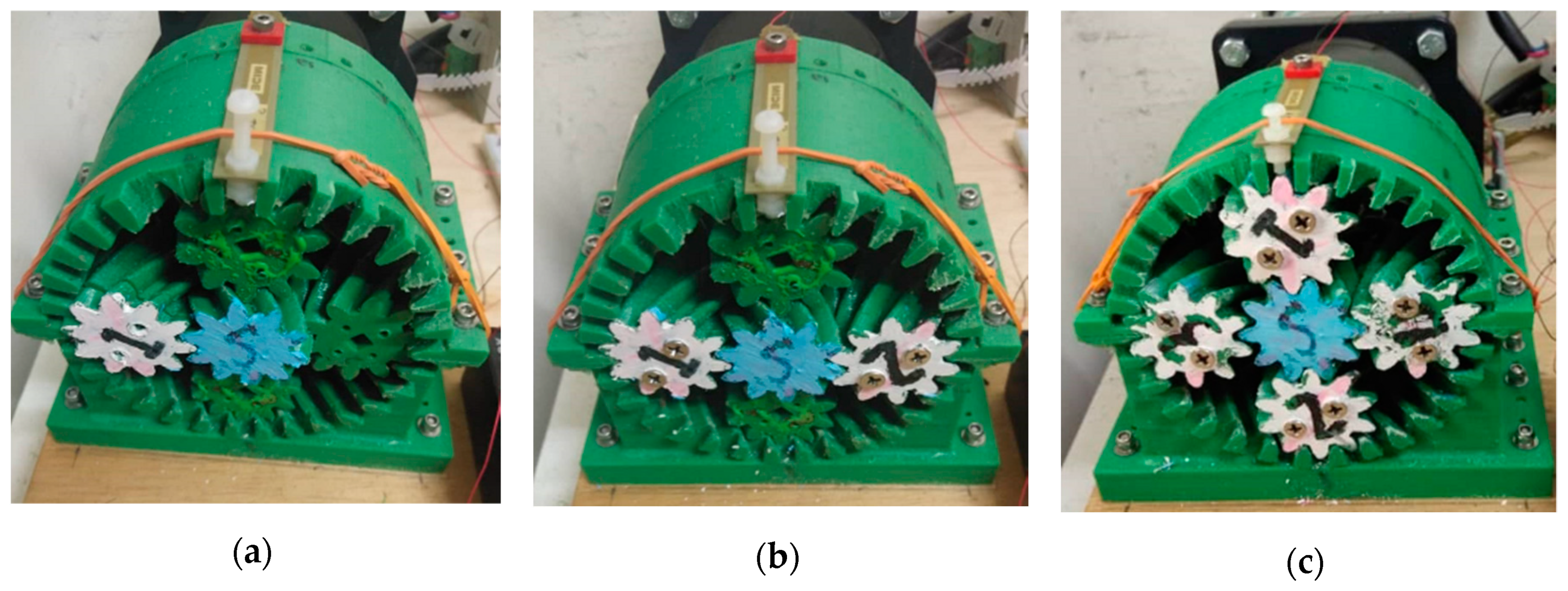
3.2.2. Effect of Planet Cover Numbers

Different numbers of planet covers have been implemented in the second experiment. The planet cover numbers represent acceleration. To prove their effect on the output voltage and thus on the output power, one, two, and four planet covers were used with one rotation speed each time to evaluate the ability of harvesting under different ranges of output power without increasing the rotation speed. The planet cover is interchangeable, and it is elementary to change it, as shown in Figure 6. The value of output voltage is measured, and the output voltage and power are calculated accordingly and considered as parameters of performance to compare each variable.
In Figure 7, the three cases of planet cover numbers (one, two, and three) are shown. It can be seen in all figures that when there is no planet cover, the planets will rotate, and there is no effect on PZT, and it will not bend at all. On the other hand, if there is any planet-cover fix on the planet, whenever it rotates, there will be a bending force on the PZT by the planet teeth.

3.2.3. Effect of Distance between PZTs

In the third experiment, the distance between PZTs has been tested. To see if the different distance between PZTs influences output power, due to the change in timing of bending for each one with the use of different planet numbers. Since the piezoelectric width is 10.4 mm with some spaces of (0.56 mm) between each cantilever and the one next to it, 30 piezoelectric cantilevers could be put all around the ring gear with a width of 11.52 mm of each one. Therefore, after dividing by four, since there are only four-planet covers, the seven cantilevers can be used in each quarter with the ability of a repeated bending force from the first planet cover and the one thereafter. Therefore, seven options of angular distances have been chosen to be tested between two cantilevers, which are 12, 24, 36, 48, 60, 72, and 84 degrees, as shown in Figure 8, using the maximum output from experiments 1 & 2, which are four-planet covers and 1500 rpm.

3.2.4. Effect of Increasing the PZT Number

Since using multiple PZTs can significantly affect the output power, different numbers of PZTs can be used to see their effect on output power, and this has been done in the fourth experiment. However, after choosing the best angular distance between two cantilevers, three options of piezoelectric cantilevers have been used to prove the concept. One, two, and three PZTs are used to evaluate their effect on output voltage and power, as shown in Figure 9. In all these cases, the PZT is connected separately to the load and rectifier, and then, the output of DC power is connected in parallel. It was found that the output power from DC output connected in parallel is better than using the series connection [65]. Three circuits have been made, one for each piezoelectric cantilever separately. Each circuit contains a bridge rectifier, and all the circuits are connected to the resistance load box to put several rings of the load in the circuit. Further, the circuits are connected in parallel.

3.2.5. Effect on the Primary System

An analysis of the impact between the PZT and teeth gear and consequently on the planetary gear system has been made. When the gears mesh in the planetary gear system to transmit the power, there are three forces that act on the teeth of the gears as shown in Figure 10. If the z-axis denotes the gear shaft, the forces can be defined as follows:
Fr represents the radial force between different gear teeth, and thus it indicates the planet gear teeth force that will bend the PZT.
The torque in the planet gear can be calculated from Equation (17).
T ( planet ) =   T ( sun )   ×   η   ×   ( Np / Ns )
where T (sun) is the input torque (N.m), which is the same as motor torque, and η is the efficiency between helical gear, which is 98% [56].
The Ft (planet) & Fr (planet) can be calculated from Equations (18) and (19), using the torque of the planet:
Ft (planet) = T/r
F r ( planet ) =   F t   ( planet )   ×   ( tan α / cos β )
From the above equations, the force (Fr) exerted on ring gear teeth and PZT is calculated. The required force that will be needed to bend the PZT was calculated, based on which PZT needs 0.522 N for each mm of bending. Thus, the force reduction percentage can be calculated.
Also, an experimental verification has been done using a laser tachometer to indicate how much the PZT will affect the primary system (planetary gear), and the reduction in the speed percentage when adding the PZT.

3.3. Modeling and Simulation

The finite element method with the COMSOL multi-physics program was used in model simulation for the system. For model simulation, the component node has been considered as a fundamental model part that contains geometry, and it is associated with the physical condition, variables, mesh, and definitions. The model that has been chosen for this study is the frequency domain, and the study node contains all the nodes that define how to solve the model.
Simulation results for evaluating the effect of rotating speed and the planet cover effect on output power are obtained to compare with the experiment results. The rotating speed that is illustrated in this study is a five rotating speed. The frequencies that affect the piezoelectric cantilever regarding planetary gear speed are 1.25, 2.5, 3.75, 5 and 6.25 Hz, and the output voltage that has been found in the simulation regarding the speed is mentioned in the results section.
For the simulation of the planet cover number effect, the acceleration that was used in the simulation and represents different planet cover numbers for different rotational speeds is measured using a laser vibrometer from national instruments. The measured acceleration and output voltages, which are shown in the simulation due to changes in planet cover numbers, are shown in the results section.

4. Results and Discussion

Four experiments have been done to evaluate their effect on enhancing the piezoelectric energy harvester output voltage and power. The results of the four experiments are depicted as follows.

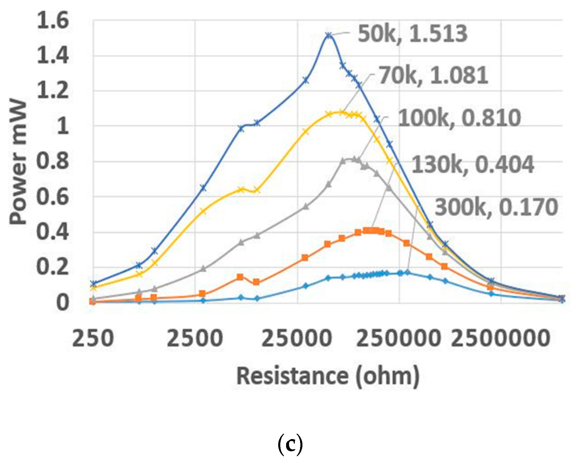
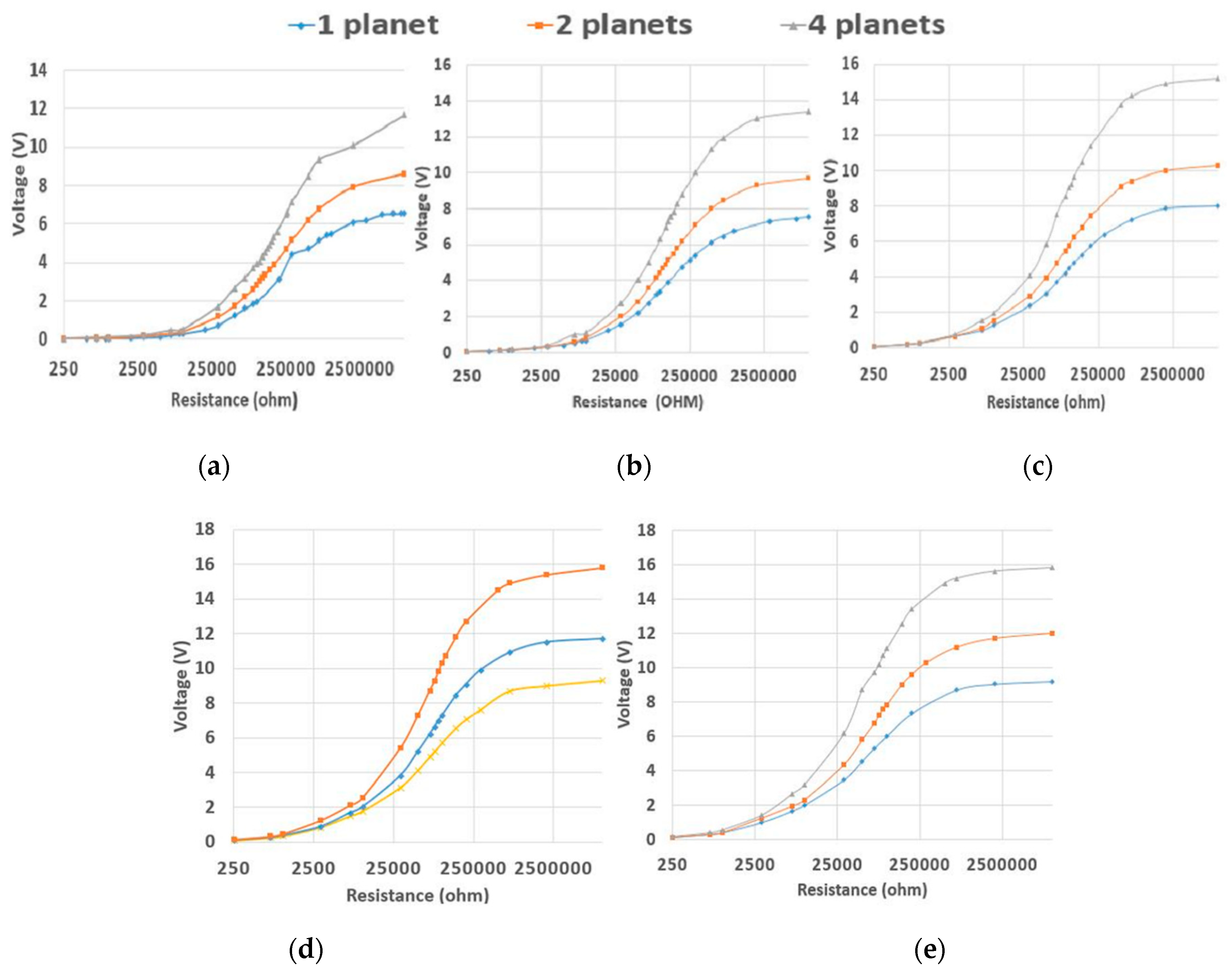
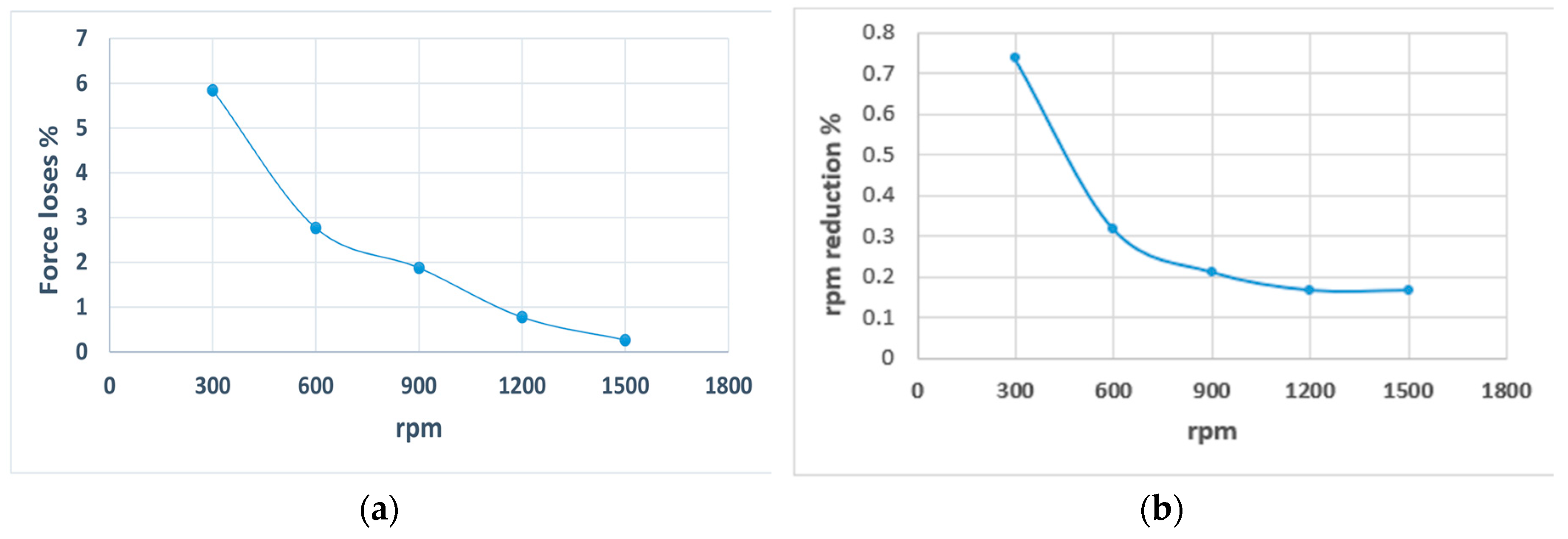
4.1. Effect of Rotational Speed

Increasing rotational speed raises the output power due to the frequency increasing in the piezoelectric. The influence of rotational speed increases with respect to voltage, and the output power has been plotted to show its effectiveness. Figure 11 shows the voltage plotted for each speed with respect to the planet numbers. Table 1 shows the experimentally measured voltage for DC with no load for each speed and for three cases of planet numbers. It was displayed in the table that the no-load DC voltage increases with an increase in rotational speed.
In Figure 11, the voltage amount increases with the increase in rotational speed (frequency) for the three planet covers cases. However, the plot for the trend of the curve of each speed almost linearly increases as resistance increases until it reaches the DC voltage (measured with no load). Then, its increment becomes very small.
Figure 12 shows the effect of rotational speed on the output power for various rotational speeds with different planet cover number cases. The optimum resistance is labeled together with its maximum power for each case. Different ranges of the motor rotation speed are implemented: 300, 600, 900, 1200 and 1500 rpm, which represent the piezoelectric input frequencies of 1.25, 2.5, 3.75, 5 and 6.25 Hz, respectively, as the input frequency that bends the piezoelectric.
Increasing rotation speed means that the frequency of bending will increase in a specific time, and thus, the output power will increase. By using one, two, and four planet covers, the effect of speed on output power in each case shows that the output power significantly increases with rotation speed increment for different planet cover numbers until it reaches its optimum amount and then starts to decrease, as shown in Figure 12. The results of the optimum resistance, measured acceleration, output power, and output power increases with the rotational speed increase, and voltage experiment results at optimum resistance compared to simulation results are summarized and presented in Table 2. Figure 10 shows the level of output power increment related to speed increases for each of the planet cover number cases. The three groups of planet cover numbers are compared here in one figure to see how the speed changes and the effect on optimizing output power for different planet cover numbers.
Figure 13 shows how the speed increase significantly affects the output power and increases it for all planet cover number cases. Also, in Table 2, it is shown that almost all the simulation voltage results are similar to the results obtained from the experiment with a range of matching from 88.2% to almost 99%. For the output voltage and power, it can also be seen that whenever speed increases, the output voltage and power increase, and this happens more obviously in four-planet cover cases. If the four planet covers case is taken as an example for output power at 300 rpm, it is 0.170 mW; however, with the use of the speed five times the original one, which is 1500 rpm, the output power increases by 8.74 times that of the original one, and the output power becomes 1.513 mW.

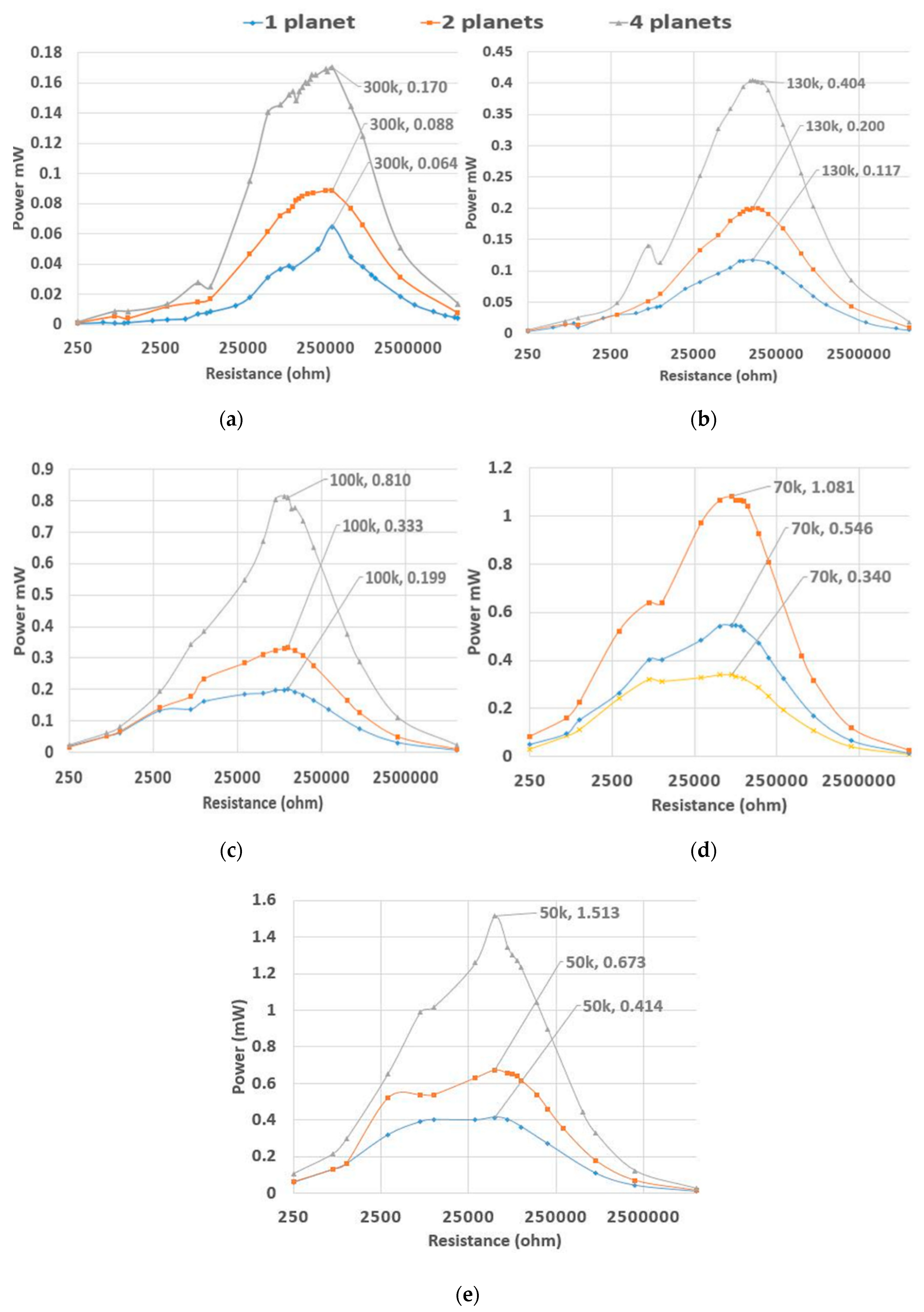
4.2. Effect of Planet Cover Numbers

Increasing planet cover numbers increases the output power due to the acceleration increasing on the piezoelectric. The influence of planet cover numbers increases with respect to voltage, and the output power has been plotted to show its effectiveness. The test is kept running to obtain the optimum power with regard to optimum resistance and voltage. Figure 13 shows the voltage plot for each planet cover number with respect to rotational speed. Table 3 shows the experimentally measured voltage for DC with no load for each planet number case and for different speeds. The table shows that the no-load DC voltage increases as the planet cover number increases.
In Figure 14, the voltage amount increases as the planet cover number increases (acceleration) for the five rotational speeds. However, the plot for the trend of the curve of each planet cover almost gradually rises with the resistance increase until it reaches the DC voltage (measured with no load), after which its increment is very small. Figure 15 shows the effect of planet cover number increases for various planet cover numbers with different rotating speeds on output power. The optimum resistance is labeled together with its maximum power for each case. Three variables are used for planet cover numbers; one, two, and four planet covers are implemented for each speed to prove their effect on output power increases.
Increasing planet cover numbers means that the acceleration and bending will increase at a particular time, and thus, the output power will increase. In all three planet covers cases with different rotational speeds, whenever the planet cover numbers increase, the output power increases, until it reaches its optimum amount and then starts to decrease, as shown in Figure 15. The results of optimum resistance, measured acceleration, output power, and output power increasing as the planet cover number increases and comparison of optimum experimental voltage with simulation voltage, are summarized and presented in Table 4. Figure 16 shows the level of output power increases related to the planet cover number increment for different rotational speed cases. Five groups of each rpm are compared to see how the planet cover numbers change and the effect on output power optimization with the use of different rotational speeds.
Figure 16 shows the effect of the planet cover number increase on output power, which increases for all rotational speed cases. Also, in Table 4, it is shown that all voltage results from the simulation are similar to the results obtained from the experiments with a range of matching from 88.2% to almost 99%. For increasing the planet cover numbers, it can be shown that whenever planet cover numbers increase, the output voltage and power increase, and this happens more obviously in the 1500 rpm speed case. If the case of 1500 rpm is taken as an example, the output power for one planet is 0.414 mW; when two planet covers are used, the output power increases to 1.62 times that of the original value and becomes 0.673 mW. When four planet covers are used, the output power is 1.513 mW, with an increase of 3.65 times the original value.

4.3. Effect of Distance between PZTs

Figure 17 shows the effect of using different angular distances between piezoelectric cantilevers on optimizing output voltage and power for different distances. It was concluded from experiments one and two that the maximum rotation speed (1500 rpm) and the use of four planet covers has the maximum influence on energy harvesting output power. However, multiple piezoelectric cantilevers are examined to see their effect on optimizing output power. For this purpose, first, the distance between the piezoelectric transducer must be examined with different angular distances to find the best distance for optimum output power.
It is clearly seen from Figure 17 that using 24 degrees can give the optimum output power compared with other angular degrees, using 1500 rpm and four planet covers, and this is due to the best sequence of repeated bending of the planet covers one after the other on the piezoelectric cantilever. Moreover, this will change as the planet cover numbers change (angular distance between them) and with the PZT width (how many PZTs can be fitted all around the ring gears).

4.4. Effect of Increasing the PZT Number

After choosing the best angular distance between two cantilevers in experiment 3, the number of PZTs number has been tested.
From Figure 18, it is observed that when using one PZT with 1500 rpm and four planet covers connected to a load of 50 kΩ, the output voltage is 8.7 V with an output power of 1.513 mW. When two PZTs are used, the optimum resistance reduces and becomes 40 kΩ because increasing the PZT number will reduce the optimum load [66]. Moreover, the output voltage becomes 11.7 V, which is not double; however, the output power becomes 3.42 mW. When three cantilevers with optimum resistance of 35 KΩ are used, the produced output voltage is 14.5, but the output power is 6.007 mW, which is more than three times the original value.

4.5. Effect on the Primary System

The results of the analysis of the impact between PZT and teeth gear and consequently on the planetary gear system are presented here. From the Equations (17)–(19), the force (Fr) exerted on the ring gear teeth and planet teeth was calculated, and it ranged from 6.78 N at 300 rpm to 41.28 N at 1500 rpm. The required force that will be needed to bend the PZT has been calculated; the PZT needs 0.522 N for each mm of bending. The maximum displacement for PZT has been chosen to be 5 mm; however, it does not have enough time to cover this distance due to fast rotation and increasing planet cover numbers. The maximum displacement at 300 rpm is 0.76 mm, and at 1500 rpm, is 0.21 mm from vibrometer measurements, and the required force for bending the PZT ranges from 0.39 N at 300 rpm to 0.1 N at 1500 rpm. The teeth force loses due to PZT bending will be 5.8% at 300 rpm and reduce it to be 0.27% at 1500 rpm, as shown in Figure 19a.
Experimental verification has been done using a laser tachometer to indicate how much the PZT will affect the primary system (planetary gear). It was found that the rotational speed of the planetary gear will reduce when adding the PZT to the system; however, the decrease in speed is insignificant. At 300 rpm, adding the PZT reduces the rotational speed by 0.73%, and this effect keeps reducing whenever speed increases due to the continuity of the system until its reduction reaches 0.166% at 1500 rpm as shown in Figure 19b.

4.6. Comparison with Previous Studies

A comparison has been made with previous studies that used gears as an excitation element, as shown in Table 5. The table shows a comparison between the input and output of the harvester parameters. It can be seen that the current work has good results in terms of output power and power density. All these studies use rotational machine (gears) as a mechanical power source, and the PZT does not rotate with the system, and thus direct wiring will be used for output power transfer.

5. Conclusions

Only a few works have been done on rotational piezoelectric energy harvesting using gears, and to the best of the authors’ knowledge, there is no research on piezoelectric energy harvesting using planetary gears. As a result, a laboratory prototype has been designed and fabricated to evaluate the performance of rotational piezoelectric energy harvesting using planetary gears. This compact design is able to operate with different ranges of speed and gives different ranges of output power from a fixed rotational speed.
Different variables have been tested through four experiments to find their influence on the output voltage and power. It has been found that increasing rotational speed can increase the output power, such as for a design with four planet gears along with different ranges of rotating speeds: 300, 600, 900, 1200, and 1500 rpm, for which the output powers are 0.17, 0.404, 0.81, 1.0812, and 1.513 mW, respectively. However, increasing the numbers of planet covers can increase the output power without increasing the rotational speed, pressing force, or any other excitation element. For increasing the planet cover number using one, two, and four planet covers, the output power is 0.414, 0.673, and 1.513 mW, respectively, at 1500 rpm. Also, increasing the PZT number increases the output power. However, after testing different distances between the PZT, it was found that a distance of 24 angular degrees between two PZTs can give the optimum output power. By using one, two, and three PZTs with 50, 40, and 35 kΩ, the output voltages are 8.7, 11.7, and 14.5 V, respectively, and the output powers are 1.513, 3.422, and 6.007 mW, respectively. The power density of PZT material is 0.00959 mW/mm3. This design can bend PZT smoothly due to the nature of planet gear moving in the planetary gear system. Also, the wiring will not cause any issue, whereas some rotational energy harvesters need a slip ring, bluetooth or any other wireless connection for output power transfer; the ring gear that PZT is fixed on will be held stationary, and the wiring will be connected directly.
In future work, a magnetic force can be used to optimize the output power and to avoid direct contact between planet teeth and PZT. Moreover, increasing the planet cover number will lead to an increase in output power. Also, the utilization of compound planetary gear for frequency up-conversion will be useful, mainly when it is applied in low-frequency applications.

Author Contributions

Conceptualization, H.J.C.; writing original draft preparation, H.J.C.; writing, review and editing, H.S.; visualization, H.J.C.; supervision, E.E.S.; project administration, H.S.; funding acquisition, E.E.S.; review and editing, A.A.; review and editing, K.A.M.R.; review and editing, software, A.B.A. All authors have read and agreed to the published version of the manuscript.

Funding

The funder for this research is UPM Faculty of engineering, grant number 9607500.

Acknowledgments

Some of the work was conducted in the Vibration Research Laboratory, Universiti Tenaga Nasional. Special thanks are extended to the technicians Muhammad Wildan and Mohd Hafizul for helping with experimental work. Also, many thanks are extended to Moaath al-rifaay and Nuradeen M. Nasidi for help and guidance in revising the paper.

Conflicts of Interest

There are no conflicts of interest to disclose.

References

  1. Yang, Z.; Zhou, S.; Zu, J.; Inman, D. High-Performance Piezoelectric Energy Harvesters and Their Applications. Joule 2018, 2, 642–697. [Google Scholar] [CrossRef] [Green Version]
  2. Wu, X.; Parmar, M.; Lee, D. A Seesaw-Structured Energy Harvester with Superwide Bandwidth for TPMS Application. IEEE/ASME Trans. Mechatron. 2014, 19, 1514–1522. [Google Scholar]
  3. Kherbeet, A.S.; Salleh, H.; Salman, B.H.; Salim, M. Vibration-based piezoelectric micropower generator for power plant wireless monitoring application. Sustain. Energy Technol. Assess. 2015, 11, 42–52. [Google Scholar] [CrossRef]
  4. Elahi, H.; Eugeni, M.; Gaudenzi, P. A Review on Mechanisms for Piezoelectric-Based Energy Harvesters. Energies 2018, 11, 1850. [Google Scholar] [CrossRef] [Green Version]
  5. Kumar, B.; Kim, S.-W. Energy harvesting based on semiconducting piezoelectric ZnO nanostructures. Nano Energy 2012, 1, 342–355. [Google Scholar] [CrossRef]
  6. Fu, H.; Yeatman, E.M. Rotational energy harvesting using bi-stability and frequency up-conversion for low-power sensing applications: Theoretical modelling and experimental validation. Mech. Syst. Signal Process. 2019, 125, 229–244. [Google Scholar] [CrossRef]
  7. Zou, H.; Zhang, W.; Li, W.; Wei, K.; Gao, Q.; Peng, Z.; Meng, G. Design and experimental investigation of a magnetically coupled vibration energy harvester using two inverted piezoelectric cantilever beams for rotational motion. Energy Convers. Manag. 2017, 148, 1391–1398. [Google Scholar] [CrossRef]
  8. Khameneifar, F.; Moallem, M.; Arzanpour, S. Modeling and Analysis of a Piezoelectric Energy Scavenger for Rotary Motion Applications. J. Vib. Acoust. 2011, 133, 011005. [Google Scholar] [CrossRef]
  9. Wu, W.; Kuo, K.; Lin, Y.; Tsai, Y. Non-contact magnetic cantilever-type piezoelectric energy harvester for rotational mechanism. Microelectron. Eng. 2018, 191, 16–19. [Google Scholar] [CrossRef]
  10. Dannier, A.; Brando, G.; Ruggiero, F. The Piezoelectric Phenomenon in Energy Harvesting Scenarios: A Theoretical Study of Viable Applications in Unbalanced Rotor Systems. Energies 2019, 12, 708. [Google Scholar] [CrossRef] [Green Version]
  11. Fan, K.; Wang, L.; Zhu, Y.; Liu, Z.; Yu, B. Performance of a multipurpose piezoelectric energy harvester. Int. J. Mod. Phys. B 2017, 31, 1741007. [Google Scholar] [CrossRef]
  12. Li, K.; He, Q.; Wang, J.; Zhou, Z.; Li, X. Wearable energy harvesters generating electricity from low-frequency human limb movement. Microsyst. Nanoeng. 2018, 4, 24. [Google Scholar] [CrossRef] [PubMed]
  13. Xie, Z.; Kwuimy, C.A.K.; Wang, Z.; Huang, W. A piezoelectric energy harvester for broadband rotational excitation using buckled beam. AIP Adv. 2018, 8, 015125. [Google Scholar] [CrossRef] [Green Version]
  14. Fu, H.; Yeatman, E.M. A methodology for low-speed broadband rotational energy harvesting using piezoelectric transduction and frequency up-conversion. Energy 2017, 125, 152–161. [Google Scholar] [CrossRef] [Green Version]
  15. Wang, Y.-J.; Chuang, T.-Y.; Yu, J.-H. Design and kinetic analysis of piezoelectric energy harvesters with self-adjusting resonant frequency. Smart Mater. Struct. 2017, 26, 095037. [Google Scholar]
  16. Wang, Y.; Chuang, T.; Lee, C. Resonant frequency self-tunable piezoelectric cantilevers for energy harvesting and disturbing torque absorbing. Sens. Actuators A Phys. 2019, 285, 25–34. [Google Scholar] [CrossRef]
  17. Zhang, Y.; Jin, Y. Stochastic dynamics of a piezoelectric energy harvester with correlated colored noises from rotational environment. Nonlinear Dyn. 2019, 98, 501–515. [Google Scholar] [CrossRef]
  18. Stamatellou, A.M.; Kalfas, A.I. Experimental investigation of energy harvesting from swirling flows using a piezoelectric film transducer. Energy Convers. Manag. 2018, 171, 1405–1415. [Google Scholar] [CrossRef]
  19. Yang, Y.; Shen, Q.; Jin, J.; Wang, Y.; Qian, W.; Yuan, D. Rotational piezoelectric wind energy harvesting using impact-induced resonance. Appl. Phys. Lett. 2014, 105, 053901. [Google Scholar] [CrossRef]
  20. Gong, Y.; Yang, Z.; Shan, X.; Sun, Y.; Xie, T.; Zi, Y. Capturing Flow Energy from Ocean and Wind. Energies 2019, 12, 2184. [Google Scholar] [CrossRef] [Green Version]
  21. An, X.; Song, B.; Tian, W.; Ma, C. Design and CFD Simulations of a Vortex-Induced Piezoelectric Energy Converter (VIPEC) for Underwater Environment. Energies 2018, 11, 330. [Google Scholar] [CrossRef] [Green Version]
  22. Kyoo, N.C.; Rho, H.H. Continuous energy harvesting method using piezoelectric element. In Proceedings of the 2015 IEEE 2nd International Future Energy Electronics Conference (IFEEC), Taipei, Taiwan, 1–4 November 2015; pp. 1–4. [Google Scholar]
  23. Nezami, S.; Jung, H.; Lee, S. Design of a disk-swing driven piezoelectric energy harvester for slow rotary system application. Smart Mater. Struct. 2019, 28, 074001. [Google Scholar] [CrossRef]
  24. Ramírez, J.M.; Gatti, C.D.; Machado, S.P.; Febbo, M. A piezoelectric energy harvester for rotating environment using a linked E-shape multi-beam. Extrem. Mech. Lett. 2019, 27, 8–19. [Google Scholar] [CrossRef]
  25. Li, M.; Wen, Y.; Li, P.; Yang, J.; Dai, X. A rotation energy harvester employing cantilever beam and magnetostrictive/piezoelectric laminate transducer. Sens. Actuators A Phys. 2011, 166, 102–110. [Google Scholar] [CrossRef]
  26. Zhang, Y.; Zheng, R.; Shimono, K.; Kaizuka, T.; Nakano, K. Effectiveness Testing of a Piezoelectric Energy Harvester for an Automobile Wheel Using Stochastic Resonance. Sensors 2016, 16, 1727. [Google Scholar] [CrossRef] [Green Version]
  27. Guan, M.; Liao, W. Design and analysis of a piezoelectric energy harvester for rotational motion system. Energy Convers. Manag. 2016, 111, 239–244. [Google Scholar] [CrossRef]
  28. Zhu, B.; Han, J.; Zhao, J.; Deng, W. Practical Design of an Energy Harvester Considering Wheel Rotation for Powering Intelligent Tire Systems. J. Electron. Mater. 2017, 46, 2483–2493. [Google Scholar] [CrossRef]
  29. Pillatsch, P.; Yeatman, E.M.; Holmes, A.S.; Wright, P.K. Wireless power transfer system for a human motion energy harvester. Sens. Actuators A Phys. 2016, 244, 77–85. [Google Scholar] [CrossRef] [Green Version]
  30. Kuang, Y.; Yang, Z.; Zhu, M. Design and characterisation of a piezoelectric knee-joint energy harvester with frequency up-conversion through magnetic plucking. Smart Mater. Struct. 2016, 25, 085029. [Google Scholar] [CrossRef]
  31. Hanif, N.H.H.M.; Mohaideen, A.J.; Azam, H.; Rohaimi, M.E. Rotational piezoelectric energy harvester for wearable devices. Cogent Eng. 2018, 5, 1430497. [Google Scholar]
  32. Choi, Y.M.; Lee, M.G.; Jeon, Y. Wearable Biomechanical Energy Harvesting Technologies. Energies 2017, 10, 1483. [Google Scholar] [CrossRef] [Green Version]
  33. Karami, M.A.; Farmer, J.R.; Inman, D.J. Parametrically excited nonlinear piezoelectric compact wind turbine. Renew. Energy 2013, 50, 977–987. [Google Scholar] [CrossRef]
  34. Pozzi, M. Synchronicity and pure bending of bimorphs: A new approach to piezoelectric energy harvesting. Smart Mater. Struct. 2018, 27, 085027. [Google Scholar] [CrossRef] [Green Version]
  35. Çelik, K.; Kurt, E.; Uzun, Y. Experimental and Theoretical Explorations on the Buckling Piezoelectric Layer Under Magnetic Excitation. J. Electron. Mater. 2017, 46, 4003–4016. [Google Scholar] [CrossRef]
  36. Gu, L.; Livermore, C. Compact passively self-tuning energy harvesting for rotating applications. Smart Mater. Struct. 2012, 21, 015002. [Google Scholar] [CrossRef]
  37. Gu, L.; Livermore, C. Passive self-tuning energy harvester for extracting energy from rotational motion. Appl. Phys. Lett. 2010, 97, 081904. [Google Scholar] [CrossRef]
  38. Febbo, M.; Machado, S.P.; Gatti, C.D.; Ramirez, J.M. An out-of-plane rotational energy harvesting system for low frequency environments. Energy Convers. Manag. 2017, 152, 166–175. [Google Scholar] [CrossRef]
  39. Hsu, J.; Tseng, C.; Chen, Y. Analysis and experiment of self-frequency-tuning piezoelectric energy harvesters for rotational motion. Smart Mater. Struct. 2014, 23, 075013. [Google Scholar] [CrossRef]
  40. Khameneifar, F.; Arzanpour, S.; Moallem, M. A Piezoelectric Energy Harvester for Rotary Motion Applications: Design and Experiments. IEEE/ASME Trans. Mechatron. 2013, 18, 1527–1534. [Google Scholar] [CrossRef]
  41. Park, J.; Lee, S.; Kwak, B.M. Design optimization of piezoelectric energy harvester subject to tip excitation. J. Mech. Sci. Technol. 2012, 26, 137–143. [Google Scholar] [CrossRef]
  42. Wei, J.; Duan, L. Piezoelectric-Based Rotary Electrical Energy Generator for Harvesting Energy from Low and Highly Variable Rotary Motion. In Proceedings of the Volume 2: Integrated System Design and Implementation; Structural Health Monitoring; Bioinspired Smart Materials and Systems; Energy Harvesting, Colorado Springs, CO, USA, 21–23 September 2015; p. V002T07A005. [Google Scholar]
  43. Xue, T.; Yeo, H.G.; Trolier-McKinstry, S.; Roundy, S. Wearable inertial energy harvester with sputtered bimorph lead zirconate titanate (PZT) thin-film beams. Smart Mater. Struct. 2018, 27, 085026. [Google Scholar] [CrossRef] [Green Version]
  44. Zhang, Y.; Zheng, R.; Nakano, K.; Cartmell, M.P. Stabilising high energy orbit oscillations by the utilisation of centrifugal effects for rotating-tyre-induced energy harvesting. Appl. Phys. Lett. 2018, 112, 143901. [Google Scholar] [CrossRef] [Green Version]
  45. Rezaei-Hosseinabadi, N.; Tabesh, A.; Dehghani, R. A Topology and Design Optimization Method for Wideband Piezoelectric Wind Energy Harvesters. IEEE Trans. Ind. Electron. 2016, 63, 2165–2173. [Google Scholar] [CrossRef]
  46. Bai, Y.; Havránek, Z.; Tofel, P.; Meggs, C.; Hughes, H.; Button, T.W. Nonlinear piezoelectric devices for broadband air-flow energy harvesting. Eur. Phys. J. Spec. Top. 2015, 224, 2675–2685. [Google Scholar] [CrossRef]
  47. Pillatsch, P.; Yeatman, E.M.; Holmes, A.S. A piezoelectric frequency up-converting energy harvester with rotating proof mass for human body applications. Sens. Actuators A Phys. 2014, 206, 178–185. [Google Scholar] [CrossRef]
  48. Larkin, M.; Tadesse, Y. HM-EH-RT: Hybrid multimodal energy harvesting from rotational and translational motions. Int. J. Smart Nano Mater. 2013, 4, 257–285. [Google Scholar] [CrossRef]
  49. Ramírez, J.M.; Gatti, C.D.; Machado, S.P.; Febbo, M. An experimentally validated finite element formulation for modeling 3D rotational energy harvesters. Eng. Struct. 2017, 153, 136–145. [Google Scholar] [CrossRef]
  50. Resali, M.S.M.; Salleh, H. Wireless condition monitoring system for rotating machinery powered by a hybrid vibration based energy harvester. J. Mech. Eng. 2017, 4, 249–267. [Google Scholar]
  51. Janphuang, P.; Lockhart, R.A.; Isarakorn, D.; Henein, S.; Briand, D.; de Rooij, N.F. Harvesting Energy from a Rotating Gear Using an AFM-Such as MEMS Piezoelectric Frequency Up-Converting Energy Harvester. J. Microelectromech. Syst. 2015, 24, 742–754. [Google Scholar] [CrossRef]
  52. Janphuang, P.; Isarakorn, D.; Briand, D.; de Rooij, N.F. Energy harvesting from a rotating gear using an impact type piezoelectric MEMS scavenger. In Proceedings of the 2011 16th International Solid-State Sensors, Actuators and Microsystems Conference, Beijing, China, 5–9 June 2011; pp. 735–738. [Google Scholar]
  53. Janphuang, P.; Lockhart, R.; Henein, S.; Briand, D.; de Rooij, N.F. On the experimental determination of the efficiency of piezoelectric impact-type energy harvesters using a rotational flywheel. J. Phys. Conf. Ser. 2013, 476, 012137. [Google Scholar] [CrossRef] [Green Version]
  54. Yang, B.; Yi, Z.; Tang, G.; Liu, J. A gullwing-structured piezoelectric rotational energy harvester for low frequency energy scavenging. Appl. Phys. Lett. 2019, 115, 063901. [Google Scholar] [CrossRef]
  55. Janphuang, P.; Lockhart, R.; Briand, D.; de Rooij, N.F. On the optimization and performances of a compact piezoelectric impact MEMS energy harvester. In Proceedings of the 2014 IEEE 27th International Conference on Micro Electro Mechanical Systems (MEMS), San Francisco, CA, USA, 26–30 January 2014; pp. 429–432. [Google Scholar]
  56. Khkgears. Net Planetary Gear. Available online: https://khkgears.net/new/gear_knowledge/gear_technical_reference/gear_systems.html (accessed on 5 August 2019).
  57. Uhl, T. Advances in Mechanism and Machine Science; Springer: Cham, Switzerland, 2019. [Google Scholar]
  58. Uicker, J.J.; Pennock, G.R.; Shigley, J.E. Theory of Machines and Mechanisms; Oxford University Press: New York, NY, USA, 2011. [Google Scholar]
  59. Damjanovic, D. Ferroelectric, dielectric and piezoelectric properties of ferroelectric thin films and ceramics. Rep. Prog. Phys. 1998, 61, 1267–1324. [Google Scholar] [CrossRef] [Green Version]
  60. Meitzler, A.H.; Tiersten, H.F.; Berlincourt, D. IEEE standard on piezoelectricity: An American National Standard; IEEE: Piscataway, NJ, USA, 1988. [Google Scholar]
  61. Hehn, T.; Manoli, Y. CMOS Circuits for Piezoelectric Energy Harvesters; Springer Series in Advanced Microelectronics; Springer: Dordrecht, The Netherlands, 2015; Volume 38, ISBN 978-94-017-9287-5. [Google Scholar]
  62. Caliò, R.; Rongala, U.; Camboni, D.; Milazzo, M.; Stefanini, C.; de Petris, G.; Oddo, C. Piezoelectric Energy Harvesting Solutions. Sensors 2014, 14, 4755–4790. [Google Scholar] [CrossRef] [PubMed] [Green Version]
  63. Thompson, S.P. Dynamo-Electric Machinery: A Manual for Students of Electrotechnics; University of California Libraries: Berkeley, CA, USA, 2009. [Google Scholar]
  64. Roshani, H.; Dessouky, S.; Montoya, A.; Papagiannakis, A.T. Energy harvesting from asphalt pavement roadways vehicle-induced stresses: A feasibility study. Appl. Energy 2016, 182, 210–218. [Google Scholar] [CrossRef]
  65. Resali, M.S.M.; Salleh, H. Development of multiple-input power management circuit for piezoelectric harvester. J. Mech. Eng. 2017, 2, 215–230. [Google Scholar]
  66. Jing, B.Y.; Leong, K.S. Power Optimization Configuration for Piezoelectric Cantilever Arrays. MATEC Web Conf. 2017, 108, 08007. [Google Scholar] [CrossRef] [Green Version]
Figure 1. The three conditions for the relationship between gears in planetary gear selecting: (a) condition No. 1, (b) condition No. 2 and (c) condition No. 3 [56].
Energies 13 00223 g001
Figure 2. (a) d33 mode piezoelectric material operation, (b) d31 mode piezoelectric material operation, (c) PZT bimorph series operation and (d) PZT bimorph parallel operation [61].
Energies 13 00223 g002
Figure 3. Test rig harvester prototype with a section view in the A-A vertical line and all part names.
Energies 13 00223 g003
Figure 4. Sequence of PZT bending for one of planet cover teeth named No. 1 and the arrow shows how much the PZT bends at each stage: (a) the whole prototype, (b) before, (no bending), (c) 50% bending, (d) 100% bending, (e) 50% bending and (f) after (no bending).
Energies 13 00223 g004
Figure 5. Circuit diagram.
Energies 13 00223 g005
Figure 6. Planet cover and how it fits in smoothly in the prototype.
Energies 13 00223 g006
Figure 7. Effect of different planet cover numbers: (a) one, (b) two and (c) three planet covers.
Energies 13 00223 g007
Figure 8. Two PZTs with an angular distance of (a) 12 degrees, (b) 24 degrees, (c) 36 degrees, (d) 48 degrees, (e) 60 degrees, (f) 72 degrees and (g) 84 degrees.
Energies 13 00223 g008
Figure 9. 45° view for PZT increasing number: (a) one PZT, (b) two PZTs and (c) three PZTs.
Energies 13 00223 g009
Figure 10. The forces that act on the teeth gear when they mesh.
Energies 13 00223 g010
Figure 11. Effect of increasing rotation speed on output voltage using different planet cover numbers: (a) one planet cover, (b) two planet covers and (c) four planet covers.
Energies 13 00223 g011
Figure 12. Effect of increasing the rotation speed on output power using different planet cover numbers: (a) one planet, (b) two planet covers and (c) four planet covers.
Energies 13 00223 g012aEnergies 13 00223 g012b
Figure 13. Increasing the level of output power with increasing rotational speed.
Energies 13 00223 g013
Figure 14. Effect of planet cover number increase on voltage increase with different rotational speeds: (a) 300 rpm, (b) 600 rpm, (c) 900 rpm, (d) 1200 rpm and (e) 1500 rpm.
Energies 13 00223 g014
Figure 15. Effect of planet cover number increase on optimizing output power with different rotational speeds of (a) 300, (b) 600, (c) 900, (d) 1200 and (e) 1500 rpm.
Energies 13 00223 g015
Figure 16. Increasing level of output power with planet cover numbers increasing.
Energies 13 00223 g016
Figure 17. Effect of distance between two cantilevers on (a) output voltage and (b) output power.
Energies 13 00223 g017
Figure 18. Effect of the piezoelectric cantilever numbers on (a) output voltage and (b) output power.
Energies 13 00223 g018
Figure 19. (a) Force loses percentage and (b) rpm reduction percentage.
Energies 13 00223 g019
Table 1. DC Voltage Amounts for the Different Speeds Measured with No Load.
DC Voltage No-Load300 rpm600 rpm900 rpm1200 rpm1500 rpm
1 Planet6.97.578.279.49.3
2 planets8.781010.311.711.9
4 Planets13.613.515.215.815.9
Table 2. Comparison of Voltage between Simulation and Experimental Results, as well as Output Power and Its Increase with the Rotational Speed Increase.
Speed300 rpm600 rpm900 rpm1200 rpm1500 rpm
Optimum Resistance300 kΩ130 kΩ100 kΩ70 kΩ50 kΩ
1 PlanetMeasured Acceleration m/s20.0450.190.430.871.41
Simulated Voltage (V)3.983.644.1874.4514.1076
Measured Voltage (V)4.393.94.474.884.55
Output Power (mW)0.06420.1170.1990.3400.414
Times of increase for Output power-1.8213.115.2956.445
2 planetsMeasured Acceleration m/s20.0570.250.571.11.96
Simulated Voltage (V)5.0424.7995.555.6285.7099
Measured Voltage (V)5.155.15.776.185.8
Output Power (mW)0.0880.20.3320.5460.673
Times of increase for Output power-2.2633.7656.1717.61
4 PlanetsMeasured Acceleration m/s20.0760.370.921.632.65
Simulated Voltage (V)6.7237.1038.9598.347.72
Measured Voltage (V)7.157.2598.78.63
Output Power (mW)0.1700.4040.811.0811.513
Times of increase for Output power/2.3724.7536.3458.74
Table 3. Output DC Voltage for Different Planet Cover Numbers Measured with No Load.
DC Voltage/No Load1 Planet2 Planet4 Planet
300 rpm6.98.7813.6
600 rpm7.5710.315.2
900 rpm8.2710.315.2
1200 rpm9.411.715.8
1500 rpm9.311.915.9
Table 4. Comparison of Voltage in Simulation and Experiment Results and Output Power and Its Increase as Planet Numbers Increase.
Rotational SpeedOptimum Resistance 1 Planet2 Planet4 Planet
300 rpm300 KΩMeasured Acceleration m/s20.0450.0570.076
Simulated Voltage (V)3.985.0426.723
Measured Voltage (V)4.395.157.15
Output Power (mW)0.06420.08840.17
Times of increase for Output power/1.3762.652
600 rpm130 KΩMeasured Acceleration m/s20.190.250.37
Simulated Voltage (V)3.644.7997.103
Measured Voltage (V)3.95.17.25
Output Power (mW)0.1170.20.404
Times of increase for Output power/1.713.455
900 rpm100 KΩMeasured Acceleration m/s20.430.570.92
Simulated Voltage (V)4.1875.558.959
Measured Voltage (V)4.475.779
Output Power (mW)0.1990.3330.81
Times of increase for Output power/1.6664.053
1200 rpm70 KΩMeasured Acceleration m/s20.871.11.63
Simulated Voltage (V)4.4515.6288.34
Measured Voltage (V)4.886.188.7
Output Power (mW)0.3400.5461.081
Times of increase for Output power/1.6033.178
1500 rpm50 KΩMeasured Acceleration m/s21.411.962.65
Simulated Voltage(V)4.10765.70997.72
Measured Voltage(V)4.555.88.63
Output Power (mW)0.4140.6731.513
Times of increase for Output power/1.6243.654
Table 5. Comparison with Previous Rotational PZT Energy Harvesting Studies That Used Gear with This Work.
Ref.InputOutput
Excitation ElementsVolumePZT Material Dimension (mm)Polarization ModeMaterial Type UserpmFrequency Actually Reach the Piezo (Hz)Resistance (Ω)Power (µW)Power Density (µW/mm3)
[52]G + M4.2---250.42.7 M1.260.3 (calculated)
[42]G + M138.6675.0 × 19.05 × 1.59 -PZT3006-60002.55 (given)
[41]G + M4.26152 mm2 × 0.028bimorph with parallel connection PZT-5A1550010003.720.87 (calculated)
[51]G + M + Mg3.5-d31PZT sheet, PSI-5A4E, 114019180 k123.43 (calculated)
[54]G61.2(10 × 18 × 0.17) × 2-thinned bulk lead zirconate titanate ceramic-7.830 k4006.54 (given)
This workPg157.76(46.4 × 6.8 × 0.25) × 2 d31PZT- 5H15006.2550 k15669.59
M is Mass, Mg is magnetic, G is gear and Pg is planetary gear.

