Experimental Investigation on the Thermal Performance of Pulsating Heat Pipe Heat Exchangers


1
Department of Refrigeration, Air Conditioning and Energy Engineering, National Chin-Yi University of Technology, Taichung 41170, Taiwan
2
Department of Mechanical Engineering, National Kaohsiung University of Science and Technology, Kaohsiung 80778, Taiwan
3
Green Energy and Environment Research Laboratories, Industrial Technology Research Institute, Hsinchu 31040, Taiwan
*
Author to whom correspondence should be addressed.
Energies 2020, 13(1), 269; https://doi.org/10.3390/en13010269
Submission received: 9 November 2019
/
Revised: 21 December 2019
/
Accepted: 31 December 2019
/
Published: 5 January 2020
(This article belongs to the Section J: Thermal Management)
Abstract
:In this study, the vertically-oriented pulsating heat pipe (PHP) heat exchangers charged with either water or HFE-7000 in a filling ratio of 35% or 50% were fabricated to exchange the thermal energy between two air streams in a parallel-flow arrangement. Both the effectiveness of the heat exchangers and the thermal resistance of PHP with a size of 132 × 44 × 200 mm, at a specific evaporator temperature ranging from 55 to 100 °C and a specific airflow velocity ranging from 0.5 to 2.0 m/s were estimated. The results show that the heat pipe charged with HFE-7000 in either filling ratio is likely to function as an interconnected array of thermosiphon under all tested conditions because of the unfavorable tube inner diameter, whereas the water-charged PHP possibly creates the pulsating movement of the liquid and vapor slugs once the evaporator temperature is high enough, especially in a filling ratio of 50%. The degradation in the thermal performance of the HFE-7000-charged PHP heat exchanger resulted from the non-condensable gas in the tube became diminished as the evaporator temperature was increased. By examining the effectiveness of the present heat exchangers, it is suggested that water is a suitable working fluid while employing the PHP heat exchanger at an evaporator temperature higher than 70 °C. On the other hand, HFE-7000 is applicable to the PHP used at an evaporator temperature lower than 70 °C.
1. Introduction
Heat is always generated during industrial processes and is dissipated into the environment as waste heat. In general, the waste heat can be classified into low temperature (<120 °C), medium temperature (120~650 °C), and high temperature (>650 °C) grades. Since the dissipation of waste heat causes both energy loss and thermal pollution, the recovery of waste heat is necessary to improve energy efficiency and reduce the thermal pollution. Traditionally, waste heat of low temperature range has not been used for electricity generation despite efforts by Organic Rankine Cycle companies [1]. Sources of low temperature waste heat mostly include heat loss from industrial products, equipment and processes, and heat discharged from combustion processes. Therefore, using heat exchangers to recover the low temperature waste heat would be the major approach rather than the thermoelectric units [2,3,4].
Over the past few decades, heat pipes have been widely employed not only for the cooling of electronic devices such as notebook PC and smart phones, but also for waste heat recovery in the form of heat pipe heat exchangers [5,6,7,8,9]. Despite the reliable and excellent heat transfer of the heat pipes, the cost of heat pipe heat exchangers could be a concern since the use of multiple heat pipes with wick structure being fabricated in each heat pipe interior wall, and the evacuation and the filling of working fluid of each heat pipe in a heat pipe heat exchanger are necessary. In addition, the wick structure in the heat pipe limits the heat transfer capability of the heat pipe. A different type of heat pipe that can be realized with a single long, meandering, and wickless capillary tube thus attracts the attention of the engineers and researchers all over the world. Such modern heat pipes, termed pulsating heat pipes (PHPs), create self-exciting pulsating movements of the liquid and vapor slugs of the working fluid inside the tube to mainly transfer sensible heat of the working fluid between evaporating section and condensing section of the pulsating heat pipes while meeting the startup criterion depending on the fluid properties and tube size. Three typical types of pulsating heat pipes, denoted as PHPs later, are commonly employed including the open-loop, closed-loop, and closed-loop with check valve PHPs [10].
In order to achieve the self-exciting pulsating movement of the working fluid in the PHPs, numerous studies on the PHPs have been conducted since 2000 to realize the effects of various factors on the successful startup of the pulsating movement of the working fluid and the thermal performance of the PHPs [11,12,13,14,15,16,17,18,19,20,21,22,23,24,25,26,27,28]. The experimental tests of the transparent PHPs were also usually performed to visualize the fluid movement in order to explain the thermal performance of the PHPs with more evidence [13,16,18,20,21,22,23,25,26,27]. According to those published results, it was found that the tube inner diameter and the thermophysical properties of the working fluid have to meet the criterion so that the working fluid in a partially filled capillary tube is able to clearly break into liquid slugs and vapor plugs in order after filling, and thus make the startup of pulsating movement possible [11,14,17,19,20,22,23,24,25,26,27]. The criterion indicates that the bond number of the pulsating heat pipe, , has to fall between 0.7 and 1.8, where D, Δρ, g, σ are the inner diameter of the PHP, the density difference between liquid and vapor phases of the working fluid, the gravitational acceleration, and the surface tension of the working fluid, respectively. Some studies of the PHPs were also carried out using functional thermal fluids as the working fluid [29,30].
In addition, the operating orientation and the total number of meandering turns of the PHPs also play a significant role on the startup of the pulsating movement of the working fluid in the PHPs. Moreover, the non-condensable gas effect on the thermal performance of pulsating heat pipes was also studied [31,32,33]. Although the existence of non-condensable gas in the pulsating heat pipes inevitably degrades the thermal performance of the PHPs and the thermal resistance of the PHPs increases with the increase of the amount of the non-condensable gas, it was found that the non-condensable gas effect on the thermal performance of the PHPs is not as evident as that on the thermal performance of traditional heat pipes and loop heat pipes, because of the different heat transfer mechanism in nature. In general, the impact of non-condensable gas on the thermal performance of heat pipes increases with the increase of the operating temperature. However, this finding is not applicable to the heat pipes charged with HFE-7000, because the solubility of air in HFE-7000 becomes higher as the temperature is increased.
Since the fabrication of PHPs are easier and cheaper than the conventional heat pipes, and numerous studies on the PHPs have reported their excellent thermal performance, PHP heat exchangers charged with either water or HFE-7000 with and without degassing were fabricated and tested in this study for low temperature waste heat recovery between hot and cold air streams at different inlet temperature of hot airflow and volumetric flow rate. Both the effectiveness and the PHP heat exchanger and the thermal resistance of PHP were estimated under different conditions in order to assess the feasibility of the application of PHP heat exchanger to the low temperature waste heat recovery.
2. Experiment
2.1. Exprimental Setup
The present experimental equipment, including a PHP heat exchanger, an air supply system, measuring instruments to monitor the air temperature, and a data acquisition system as shown in Figure 1, was established in a room where both the temperature and relative humidity of air can be steadily maintained at 30 °C and 70% RH, respectively. The air supply system used two inverter centrifugal blowers to respectively force both air streams to flow through the individual duct in a parallel way. A heater installed behind the inlet was used to maintain specific air temperatures at the inlet of the duct, and the heater power was recorded by a power meter (WT230, YOKOGAWA). The T-type thermocouples with resolution of ± 0.1 °C was installed at both inlet and outlet of both air ducts to monitor the temperature of the air streams. The arrangement of the T-type thermocouples over the cross section of the air ducts at both inlet and outlet was also illustrated in Figure 1 in order to measure the air temperature at those cross sections. In addition, a vortex flow meter (Turbo CT-LUGB-2) that measures the volumetric flow rate ranging from 8 to 300 m3/h with an accuracy of ± 1.5% was used to measure the airflow rate in the cold air duct, while the other flow meter (SS30.301, SCHMIDT) that measures the volumetric flow rate ranging from 0.8 to 229 m3/h with an accuracy of ± 3% was used to measure the airflow rate in the hot air duct. Once the volumetric flow rate of the airflow at the inlet is obtained, the air flow velocity can be estimated by dividing volumetric flow rate with air density and the cross-section area of the inlet. All measured signals were transmitted by a data acquisition unit (DR230, YOKOGAWA) and recorded by a personal computer for further analysis.
The PHP tested in this study consists of eighteen 6 mm diameter bare tubes made of copper. Note that the inner diameter of those tubes is 5 mm with a tube wall thickness of 0.5 mm as shown in Figure 2. The assembly of the bare tubes and a total of 124 pieces of 0.1 mm thick aluminum alloy plate fin using solder accomplishes a PHP heat exchanger of 132 × 44 × 200 mm in external dimensions. The PHP was vertically embedded in the plate fin array with the evaporating section being held at the bottom. The spacing between two adjacent plate fins was 1.6 mm. In addition, the bare tubes were arranged in three staggered rows whose transverse and longitudinal pitch between the tubes were 18 and 14 mm, respectively, as shown in Figure 2.
The heat exchanger was equally divided into two sections using a baffle, and each section was situated in an individual air duct in order to exchange thermal energy between the cold airflow and hot airflow via the heat exchanger, as depicted in Figure 3a. Four T-type thermocouples were attached to the evaporating section and condensing section on both top and bottom elbows of the PHP, Te1, Te2, Tc1, and Tc2 as indicated in Figure 3a, to capture the PHP surface temperature. The outer walls of both air ducts were wrapped using fiberglass whose thermal conductivity is 0.043 W/m·K to prevent the heat loss. The picture of the actual heat exchanger used in this study is shown in Figure 3b. Both the cold air and hot air were pumped into individual air ducts at room temperature and at a specific temperature between 55 and 100 °C, respectively. After carefully cleaning those bare tubes, the degassing of the bare tubes was carried out by a rotary vane pump (Alcatel Pascal 2015SD, Pfeiffer Vacuum, Aßlar, Germany) with the vacuum pressure of the system being lowered to 4 × 10⁻³ torr and remained unchanged for over six hours after the rotary vane pump was turned off. Subsequently, either deionized water with the resistivity of 18.2 MΩ·cm or 3M™ Novec™ 7000 Engineered Fluid (HFE-7000) (3M Company, Minnesota, U.S.) as the working fluid was charged into the tubes, followed by the sealing of the filling port to realize the present PHPs. Notice that a particular PHP without being degassed prior to the filling of HFE-7000 was also fabricated and tested in this study. This case will be denoted as “w/o DG" in the following section. The filling ratio of the working fluid in the pulsating heat pipes was either 35% or 50%.
2.2. Data Reduction
Based on the experimental setup, the thermal energy exchanged between the airflow and the PHP in both cold and hot air ducts can be determined using the following equations,
where , and Cp denote the heat transfer rate (W) between the air stream and the heat exchanger, the air mass flow rate (kg/s), and the specific heat of air at constant pressure (J/kg·°C). The subscripts, c, h, in, out, represent the cold air, hot air, inlet, and outlet, respectively. The air temperature at the inlet and outlet of both streams, Te, in, Te, out, Tc, in, Tc, out, was schematically shown in Figure 1. Note that the section of the PHP located in the hot air duct and cold air duct corresponds to the evaporating and condensing sections of the PHP, respectively. Based on the requirement of energy balance between the hot airflow and cold airflow, the values estimated by Equations (1) and (2) should be equal to each other if the assumption of hermetic, and adiabatic duct walls is applicable. In addition, both the mass flow rates and have to be identical at the inlet and outlet to satisfy the mass balance criterion.
The heat transfer rate between the airflow and the heat exchanger was defined as the average of and , as follows,
After estimating , the dimensionless effectiveness of the heat exchanger, ε, incorporating a PHP can be estimated by the following equation.
Where is the maximum possible heat transfer rate (W) defined as the product of the minimum heat capacity rate of air, Cmin, and the temperature difference at the inlet between the hot air and the cold air.
The Cmin is equal to the heat capacity rate of hot air, Ch, or the heat capacity rate of cold air, Cc, whichever is smaller. Ch and Cc are expressed as Equations (6) and (7), respectively.
In addition, in order to compare the present PHP performance with the published data in the literature, the thermal resistance of the PHP, R, is defined as follows,
where Te1, Te2, Tc1, and Tc2 as indicated in Figure 3a are the surface temperature of the evaporating section and condensing section, respectively.
The data substituted in the aforementioned equations such as the mass flow rate and temperature of air were captured at the steady state in which the variation of the average temperature of the air at the nine measured positions at the inlet and outlet was less than 0.5 °C for 30 min.
3. Results and Discussion
3.1. Uncertainty
In order to examine the effect of the working fluid in the PHP on the performance of the PHP heat exchanger, various factors including the inlet temperature of the hot air ranging from 55 to 100 °C, the filling ratio, and the air velocity ranging from 0.5 to 2.0 m/s, were tested. Note that the air velocity in both air ducts was always kept identical, while the inlet temperature of the cold air was constant at room temperature in this study. The uncertainty of both effectiveness and average heat transfer rate of the heat exchanger were estimated under various conditions. The uncertainty is used to refer to the interval around the measured value within which the true value is believed to lie. The uncertainty listed in Table 1 was estimated using the method described in [34] at various conditions. The uncertainty of average heat transfer rate and the effectiveness of the heat exchanger is almost held constant at 3.00% and 4.25%, respectively, among the conditions listed in Table 1. In addition, the uncertainty of the thermal resistance of the PHP charged with either water or HFE-7000 in both filling ratios at airflow velocity of 0.5 m/s ranges from 3.09% to 3.92% estimated using the uncertainty of the average heat transfer rate listed in Table 1.
3.2. Thermal Performance of the Heat Exchanger
The heat transfer rate between the airflow and the heat exchanger in the cold and hot air ducts were estimated as and based on Equations (1) and (2), respectively. The trend of and versus evaporator temperature are similar, except some discrepancy between the value of and because of the heat loss through the walls of the air duct. The amount of heat loss depends on the evaporator temperature and the airflow velocity. Figure 4a shows the heat transfer rate of four different PHP heat exchangers estimated by Equation (3) versus the evaporator temperature, Te, in, at airflow velocity of 0.5 m/s. The PHPs were water-charged, HFE-7000-charged with and without degassing in a filling ratio of 35%, and an empty one without working fluid in the tube. It can be found in Figure 4a that the heat transfer rate linearly increased as the evaporator temperature was increased. In addition, the heat transfer rate of the degassed, HFE-7000-charged PHP heat exchanger was slightly higher than that of the water-charged PHP heat exchanger at an evaporator temperature, Te, in, lower than 70 °C. The difference in heat transfer rate between the HFE-7000-charged and water-charged PHP heat exchangers became invisible at an evaporator temperature, Te, in, higher than 70 °C.
In addition, the heat transfer rate of the heat exchanger possessing a HFE-7000-charged PHP without being degassed in Figure 4a has to be mentioned in particular. Although a great deal of non-condensable gas existed in the HFE-7000-charged PHP tubing, its heat transfer rate was quite high. For example, the heat transfer rate reached 187 W which was 5% lower than that of the degassed, HFE-7000-charged PHP at an evaporator temperature of 100 °C. It means that the impact of the non-condensable gas on the heat transfer performance of the HFE-7000-charged PHP was not as great as expected. Moreover, it is seen that the difference in heat transfer rate between both heat exchangers possessing HFE-7000-charged PHP became less as the evaporator temperature was increased. Since the air solubility in HFE-7000 increases with the rise of temperature, the heat transfer degradation of the PHP affected by the non-condensable gas become weak as the temperature is increased. The heat transfer rate of an empty PHP without charging any working fluid is also plotted in Figure 4a as a baseline since the overall thermal resistance of the heat exchanger is associated with the thermal resistance of the forced convection between the hot and cold air and the plate-fin array, and the conduction thermal resistance via the tube wall. Since the former thermal resistance of the empty PHP is similar to what happens to those heat exchangers with a fluid-charged pulsating heat pipe, the latter one becomes an indicator to show how greatly the thermal performance of the heat exchanger is enhanced with a fluid-charged PHP.
All abovementioned phenomena also revealed in Figure 4b at airflow velocity of 2.0 m/s, and the heat transfer rate of those heat exchangers in Figure 4b is increased by a factor ranging from 2.9 to 1.8 compared with the results in Figure 4a depending on the PHP condition. Equations (1) and (2) show that the heat transfer rate is in proportion to both the mass flow rate and the temperature difference between the inlet and outlet of the airflow. The higher heat transfer rate in Figure 4b was expected at a given evaporator temperature because the air mass flow rate in Figure 4b was higher than that in Figure 4a.
Despite the similar heat transfer rate between the water-charged and HFE-7000-charged PHP heat exchangers shown in both Figure 4a,b, the heat transfer mechanism within the pulsating heat pipes seems to be slightly different. Table 2 shows that some characteristics of HFE-7000, such as the low latent heat of vaporization, low viscosity, and low surface tension, as well as the high rate of change in pressure with respect to temperature at saturated conditions ()sat, which refers to a steep vaporization curve in the phase diagram over a temperature range of interest as shown in Figure 5, are favorable to function the pulsating movement of the vapor and liquid slugs inside the tube. However, the pulsating movement of the vapor and liquid slugs of the HFE-7000 inside the tube could hardly happen according to the inspection of the surface temperature variation in both evaporating and condensing sections as shown in Figure 6a. It turns out that the heat pipe embedded in the heat exchanger acts like an interconnected array of two-phase thermosiphon rather than a pulsating heat pipe, because of the oversized inner tube [14] tested, 5 mm, in this study. In contrast, the thermophysical properties of water make water applicable to the PHP having a larger tube diameter. Figure 6b shows that the pulsating movement of the liquid and vapor slugs seems to be unstable. The detection of more irregular temperature oscillations in the evaporating section than those in the condensing section of the water-charged PHP at low evaporator temperature in Figure 6b, marked as LET, reflects the fact that pulsating movement of the vapor and liquid slugs of the water in the evaporating section of the PHP might not always reach the condensing section of the PHP. At high evaporator temperature, marked as HET in Figure 6b, the bulk circulation of the liquid and vapor slugs seems to occur due to the detection of almost simultaneous surface temperature oscillations in both evaporation and condensing sections. The surface temperature recording in both evaporation and condensing sections of the HFE-7000-charged PHP without degassing at various hot air temperatures is similar to that revealed in Figure 6a.
Figure 7 shows the thermal resistance of the PHPs charged with water and HFE-7000 in the filling ratio of 35% and 50% at various evaporator temperatures at airflow velocity of 0.5 m/s. It shows that the thermal resistance of both PHPs in a filling ratio of 35% monotonously decreased as the evaporator temperature increased. Although the thermal resistance of the PHP charged with HFE-7000 in a filling ratio of 35% is lower than that of the PHP charged with water in the same filling ratio at an evaporator temperature lower than 85 °C, the thermal resistance of these PHPs is close to each other as 0.04 °C/W at an evaporator temperature of 100 °C. However, it can be found that the thermal resistance of the PHP charged with water in a filling ratio of 50% exhibits a peak at the evaporator temperature of 70 °C, which makes it quite particular compared with the other three curves in Figure 7. The similar jump in the PHP thermal resistance versus heating power in [27] was explained as the flow pattern transition from the thermosiphon-type liquid/vapor counter-current annular flow to the pulsating motion of the working fluid, according to the inspection of the synchronized flow visualization images. Figure 7 shows that the thermal resistance of the present PHP ranged from 0.24 to 0.03 °C/W with the heating power ranging from 50 to 200 W, as shown in Figure 4a. The reported thermal resistance of the PHP charged with various working fluids in the literature was summarized in Table 3 for comparison. It can be found from Table 3 that the thermal resistance of the PHP distributed over a wide range between 9.5 and 0.02 °C/W, depending on the selection of working fluid, the tube material, tube diameter, and the heating power.
Figure 8 shows that higher evaporator temperatures result in higher effectiveness but higher airflow velocity result in lower effectiveness, which is an identical finding to that in [7]. Since the temperature difference of either hot airflow or cold airflow between the inlet and outlet reduces as the airflow velocity is increased at a given evaporator temperature, and the mass flow rate plays a minor role in Equation (4), the effectiveness of the heat exchangers reduces as the airflow velocity is increased at a given evaporator temperature. Since the hot and cold airflows pass the PHP heat exchanger in this study in a parallel-flow arrangement, and the mass flow rate and specific heat of the hot and cold airflows are almost identical, the upper limit of the effectiveness of the heat exchanger would be approximately 50% with an identical temperature of both airflows at the outlet. The effectiveness of the heat pipe heat exchanger tested in [7] ranged from 13% to 16% at the inlet temperature of 100 °C, whereas the effectiveness of the PHP heat exchanger charged with HFE-7000 in a filling ratio of 35% in this study ranged from 31% to 46% at an evaporator temperature of 100 °C. In addition, it is found that the effectiveness of the heat exchanger in both Figure 8b,c increases more rapidly than that in Figure 8a at low evaporator temperature. As the evaporator temperature is increased, the transition of the heat transfer mechanism of the water-charged PHP occurs as discussed on Figure 6, causing the significant increase of the effectiveness at the low evaporator temperature and then the slightly increase at the evaporator temperature higher than 70 °C. As for Figure 8c, because the negative impact of the non-condensable gas on the thermal performance of the HFE-7000-charged PHP without degassing becomes weak as the evaporator temperature is increased as explained in [33], the effectiveness of the heat exchanger continuously increases until a higher evaporator temperature is reached, for example 85 °C.
As the filling ratio of the working fluid further increased to 50%, the surface temperature variation in both evaporation and condensing sections and the effectiveness of the fluid-charged heat exchanger at different evaporator temperature stepwise increased from 55 to 100 °C at an airflow velocity ranging from 0.5 to 2.0 m/s were reported in both Figure 9 and Figure 10. It is observed in Figure 9a that, at low evaporator temperature, indicated as LET, the temperature difference between the evaporating section and the condensing section became great once the surface temperature oscillation in the evaporating section or condensing section was detected. The heat transfer between both sections of the heat pipe was somehow blocked at low evaporator temperature, resulting in low effectiveness of the heat exchanger at an evaporator temperature of 55 and 70 °C in Figure 9b. On the contrary, the intense surface temperature oscillation in both evaporating section and condensing section at a high evaporator temperature, indicated as HET, causes a little temperature difference between both sections of the heat pipe. Therefore, an obvious jump in both effectiveness of the heat exchanger at an evaporator temperature of 85 °C can be observed in Figure 9b. Compared to the effectiveness of the heat exchanger shown in both Figure 8b and Figure 9b, it is seen that the filling ratio of the water-charged PHP has a significant effect on the effectiveness of the PHP heat exchanger at a low evaporator temperature.
Figure 10 shows the surface temperature in both evaporation and condensing sections and the effectiveness of the PHP heat exchanger charged with HFE-7000 in a filling ratio of 50% at different evaporator temperatures at airflow velocity ranging from 0.5 to 2.0 m/s. Similar to the results revealed in Figure 6a, the surface temperature oscillation was seldom detected in Figure 10a because the HFE-7000-charged copper tube functioned as an interconnected array of two-phase thermosiphon. Therefore, the effectiveness of the PHP heat exchanger charged with HFE-7000 was smoothly increased as the evaporator temperature was increased as shown in Figure 10b, similar to the effectiveness shown in Figure 8a. However, the comparison of the effectiveness of the heat exchanger charged with different amount of HFE-7000 with identical airflow velocity and evaporator temperature in both Figure 8a and Figure 10b shows that higher filling ratio of HFE-7000 in the present heat exchanger resulted in lower effectiveness. This is likely because the deeper the working fluid, the higher the thermal resistance between the evaporating section and the condensing section of the thermosiphon. Since the present heat exchangers were all operated at a given evaporator temperature instead of heating power, a high thermal resistance of the heat pipe transported low heat transfer rate at a given temperature different between both sections of the heat pipe, resulting in low effectiveness.
4. Conclusions
In this study, the heat exchangers comprising a plate-fin array and a vertically-oriented pulsating heat pipe charged with either water or HFE-7000 in a filling ratio of 35% or 50% were fabricated and tested to measure both the effectiveness of the heat exchanger and thermal resistance of the PHP at a specific evaporator temperature ranging from 55 to 100 °C and a specific airflow velocity ranging from 0.5 to 2.0 m/s. Both the hot air and cold air streams enter the heat exchanger in a parallel-flow arrangement.
The results show that
- The heat pipe charged with HFE-7000 in each filling ratio is likely to function as an interconnected array of thermosiphon under all tested conditions because the tube inner diameter is too large to cause the start-up of pulsating movement of the vapor and liquid slugs, whereas the water-charged PHP possibly acts as a PHP once the evaporator temperature is high enough, especially in a filling ratio of 50%.
- The difference in effectiveness of the PHP heat exchangers charged with HFE-7000 with and without degassing became less as the evaporator temperature was increased, because the negative impact on the thermal performance of the HFE-7000-charged heat pipe become diminished.
- Water is a better working fluid than HFE-7000 in this study while employing the PHP heat exchanger at an evaporator temperature higher than 70 °C. On the other hand, HFE-7000 is a better working fluid while employing the PHP heat exchanger at an evaporator temperature lower than 70 °C.
- The effectiveness of the HFE-7000-charged PHP heat exchanger in a filling ratio of 35% reached 43% at an evaporator temperature of 55 °C at an airflow velocity of 0.5 m/s, while that of the water-charged one in a filling ratio of 35% was approximately 47% at an evaporator temperature of 100 °C at an airflow velocity of 0.5 m/s.
Author Contributions
Conceptualized, conceived, and designed the experiments, K.-S.Y., S.-K.W., and C.-Y.T.; Setup of the experiment and experimental measurement, M.-Y.J.; Data curation and writing, J.-C.S. All authors have read and agreed to the published version of the manuscript.
Funding
This research was funded by both the Bureau of Energy of the Ministry of Economic Affairs, and Ministry of Science and Technology of Taiwan, grant number MOST 107-2221-E-992-077-MY2 and MOST 108-2628-E-992-001-MY3.
Acknowledgments
The authors gratefully acknowledge the financial support from the Bureau of Energy of the Ministry of Economic Affairs, and Ministry of Science and Technology of Taiwan under the contracts of MOST 107-2221-E-992-077-MY2 and MOST 108-2628-E-992-001-MY3.
Conflicts of Interest
The authors declare no conflict of interest.
Nomenclature
| A | heat transfer surface area (m2) |
| C | heat capacity rate (J/°C·s) |
| Cmin | minimum heat capacity rate (J/°C·s) |
| specific heat of air at constant pressure (J/kg·°C) | |
| mass flow rate (kg/s) | |
| heat transfer rate (W) | |
| maximum possible heat transfer rate (W) | |
| thermal resistance of PHP (°C/W) | |
| Te | air temperature in hot air duct (°C) |
| average surface temperature in evaporating section (°C) | |
| Tc | air temperature in cold air duct (°C) |
| average surface temperature in condensing section (°C) | |
| Greek symbols | |
| ε | effectiveness |
| Subscripts | |
| avg | average |
| c | cold air |
| h | hot air |
| in | inlet |
| out | outlet |
References
- Waste Heat Recovery Unit. Available online: https://en.wikipedia.org/wiki/Waste_heat_recovery_unit (accessed on 7 December 2019).
- Srinivasan, B.; Gucci, F.; Boussard-Plédel, C.; Cheviré, F.; Reece, M.J.; Tricot, S.; Calvez, L.; Bureau, B. Enhancement in thermoelectric performance of n-type Pb-deficit Pb-Sb-Te alloys. J. Alloy. Compd. 2017, 729, 198–202. [Google Scholar] [CrossRef]
- Srinivasan, B.; Fontaine, B.; Gucci, F.; Dorcet, V.; Saunders, T.G.; Yu, M.; Cheviré, F.; Boussard-Pledel, C.; Halet, J.F.; Gautier, R.; et al. Effect of the Processing Route on the Thermoelectric Performance of Nanostructured CuPb18SbTe20. Inorg. Chem. 2018, 57, 12976–12986. [Google Scholar] [CrossRef] [PubMed]
- Srinivasan, B.; Gellé, A.; Gucci, F.; Boussard-Pledel, C.; Fontaine, B.; Gautier, R.; Halet, J.F.; Reece, M.J.; Bureau, B. Realizing a stable high thermoelectric zT ~ 2 over a broad temperature range in Ge1−x−yGaxSbyTe via band engineering and hybrid flash-SPS processing. Inorg. Chem. Front. 2019, 6, 63–73. [Google Scholar] [CrossRef]
- Yau, Y.H.; Ahmadzadehtalatapeh, M. A review on the application of horizontal heat pipe heat exchangers in air conditioning systems in the tropics. Appl. Therm. Eng. 2010, 30, 77–84. [Google Scholar] [CrossRef]
- Zhang, L.; Zhang, Y.-F. Research on Energy Saving Potential for Dedicated Ventilation Systems Based on Heat Recovery Technology. Energies 2014, 7, 4261–4280. [Google Scholar] [CrossRef] [Green Version]
- Mroue, H.; Ramos, J.B.; Wrobel, L.C.; Jouhara, H. Experimental and numerical investigation of an air-to-water heat pipe-based heat exchanger. Appl. Therm. Eng. 2015, 78, 339–350. [Google Scholar] [CrossRef] [Green Version]
- Zhang, L.; Zhang, Y.-F. Research on Heat Recovery Technology for Reducing the Energy Consumption of Dedicated Ventilation Systems: An Application to the Operating Model of a Laboratory. Energies 2016, 9, 24. [Google Scholar] [CrossRef] [Green Version]
- Yang, K.-S.; Wang, J.-S.; Wu, S.-K.; Tseng, C.-Y.; Shyu, J.-C. Performance Evaluation of a Desiccant Dehumidifier with a Heat Recovery Unit. Energies 2017, 10, 2006. [Google Scholar] [CrossRef] [Green Version]
- Rittidech, S.; Terdtoon, P.; Murakami, M.; Kamonpet, P.; Jompakdee, W. Correlation to Predict Heat Transfer Characteristics of a Closed-end Oscillating Heat Pipe at Normal Operating Condition. Appl. Therm. Eng. 2003, 23, 497–510. [Google Scholar] [CrossRef]
- Shafii, M.B.; Faghri, A.; Zhang, Y. Thermal Modeling of Unlooped and Looped Pulsating Heat Pipes. J. Heat Trans. 2001, 123, 1159–1172. [Google Scholar] [CrossRef]
- Charoensawan, P.; Khandekar, S.; Groll, M.; Terdtoon, P. Closed loop pulsating heat pipes Part A: Parametric experimental investigations. Appl. Therm. Eng. 2003, 23, 2009–2020. [Google Scholar] [CrossRef]
- Khandekar, S.; Charoensawan, P.; Groll, M.; Terdtoon, P. Closed loop pulsating heat pipes Part B: Visualization and semi-empirical modeling. Appl. Therm. Eng. 2003, 23, 2021–2033. [Google Scholar] [CrossRef]
- Khandekar, S.; Dollinger, N.; Groll, M. Understanding operational regimes of closed loop pulsating heat pipes: An experimental study. Appl. Therm. Eng. 2003, 23, 707–719. [Google Scholar] [CrossRef] [Green Version]
- Khandekar, S.; Groll, M. An insight into thermo-hydrodynamic coupling in closed loop pulsating heat pipes. Int. J. Therm. Sci. 2004, 43, 13–20. [Google Scholar] [CrossRef]
- Xu, J.L.; Li, Y.X.; Wong, T.N. High speed flow visualization of a closed loop pulsating heat pipe. Int. J. Heat Mass Transf. 2005, 48, 3338–3351. [Google Scholar] [CrossRef]
- Xu, J.L.; Zhang, X.M. Start-up and steady thermal oscillation of a pulsating heat pipe. Heat Mass Transf. 2005, 41, 685–694. [Google Scholar] [CrossRef]
- Qu, W.; Ma, H.B. Theoretical analysis of startup of a pulsating heat pipe. Int. J. Heat Mass Transf. 2007, 50, 2309–2316. [Google Scholar] [CrossRef]
- Zhang, Y.; Faghri, A. Advances and Unsolved Issues in Pulsating Heat Pipes. Heat Transf. Eng. 2008, 29, 20–44. [Google Scholar] [CrossRef] [Green Version]
- Lin, Y.-H.; Kang, S.-W.; Wu, T.-Y. Fabrication of polydimethylsiloxane (PDMS) pulsating heat pipe. Appl. Therm. Eng. 2009, 29, 573–580. [Google Scholar] [CrossRef]
- Wilson, C.; Borgmeyer, B.; Winholtz, R.A.; Ma, H.B.; Jacobson, D.; Hussey, D. Thermal and Visual Observation of Water and Acetone Oscillating Heat Pipes. J. Heat Trans. 2011, 133. [Google Scholar] [CrossRef]
- Chien, K.-H.; Lin, Y.-T.; Chen, Y.-R.; Yang, K.-S.; Wang, C.-C. A novel design of pulsating heat pipe with fewer turns applicable to all orientations. Int. J. Heat Mass Transf. 2012, 55, 5722–5728. [Google Scholar] [CrossRef]
- Youn, Y.J.; Kim, S.J. Fabrication and evaluation of a silicon-based micro pulsating heat spreader. Sens. Actuators A Phys. 2012, 174, 189–197. [Google Scholar] [CrossRef]
- Liu, X.; Chen, Y.; Shi, M. Dynamic performance analysis on start-up of closed-loop pulsating heat pipes (CLPHPs). Int. J. Therm. Sci. 2013, 65, 224–233. [Google Scholar] [CrossRef]
- Tseng, C.-Y.; Yang, K.-S.; Chien, K.-H.; Jeng, M.-S.; Wang, C.-C. Investigation of the performance of pulsating heat pipe subject to uniform/alternating tube diameters. Exp. Therm. Fluid Sci. 2014, 54, 85–92. [Google Scholar] [CrossRef]
- Yang, K.-S.; Cheng, Y.-C.; Liu, M.-C.; Shyu, J.-C. Micro pulsating heat pipes with alternate microchannel widths. Appl. Therm. Eng. 2015, 83, 131–138. [Google Scholar] [CrossRef]
- Qu, J.; Wu, H.; Cheng, P. Start-up, heat transfer and flow characteristics of silicon-based micro pulsating heat pipes. Int. J. Heat Mass Transf. 2012, 55, 6109–6120. [Google Scholar] [CrossRef]
- Tseng, C.-Y.; Wu, H.-M.; Wong, S.-C.; Yang, K.-S.; Wang, C.-C. A Novel Thermal Module with 3-D Configuration Pulsating Heat Pipe for High-Flux Applications. Energies 2018, 11, 3425. [Google Scholar] [CrossRef] [Green Version]
- Wang, S.; Lin, Z.; Zhang, W.; Chen, J. Experimental study on pulsating heat pipe with functional thermal fluids. Int. J. Heat Mass Transf. 2009, 52, 5276–5279. [Google Scholar] [CrossRef]
- Ji, Y.; Ma, H.; Su, F.; Wang, G. Particle size effect on heat transfer performance in an oscillating heat pipe. Exp. Therm. Fluid Sci. 2011, 35, 724–727. [Google Scholar] [CrossRef]
- Senjaya, R.; Inoue, T. Effects of non-condensable gas on the performance of oscillating heat pipe, part I: Theoretical study. Appl. Therm. Eng. 2014, 73, 1387–1392. [Google Scholar] [CrossRef]
- Senjaya, R.; Inoue, T. Effects of non-condensable gas on the performance of oscillating heat pipe, part II: Experimental study. Appl. Therm. Eng. 2014, 73, 1393–1400. [Google Scholar] [CrossRef]
- Sun, C.-H.; Tseng, C.-Y.; Yang, K.-S.; Wu, S.-K.; Wang, C.-C. Investigation of the evacuation pressure on the performance of pulsating heat pipe. Int. Commun. Heat Mass 2017, 85, 23–28. [Google Scholar] [CrossRef]
- Moffat, R.J. Describing the Uncertainties in Experimental Results. Exp. Therm. Fluid Sci. 1988, 52, 3–17. [Google Scholar] [CrossRef] [Green Version]
Figure 1.
Schematic diagram of the present experimental setup.
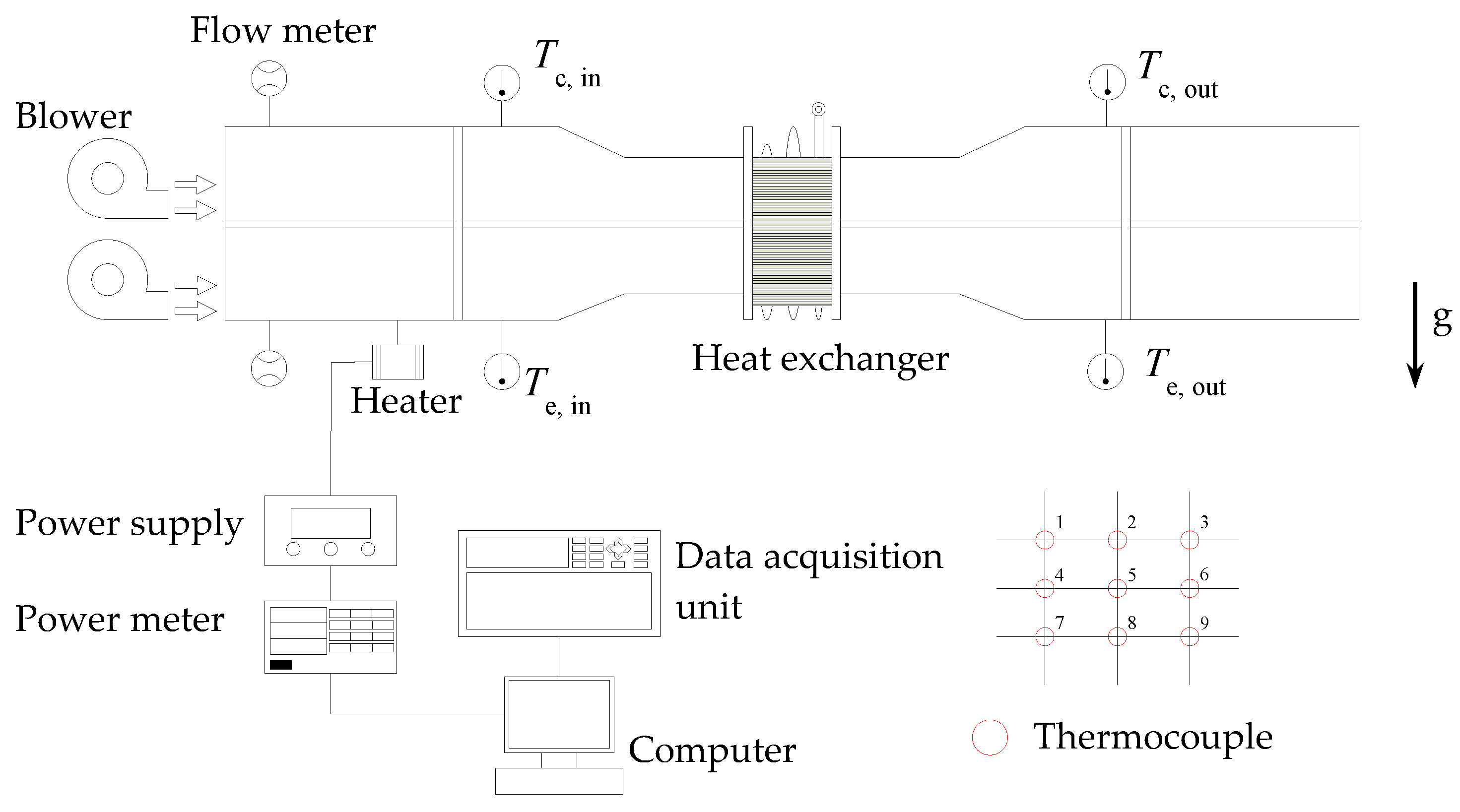
Figure 2.
Arrangement of the pulsating heat pipes with respect to the 110 mm long and 43 mm wide plate fin.
Figure 2.
Arrangement of the pulsating heat pipes with respect to the 110 mm long and 43 mm wide plate fin.
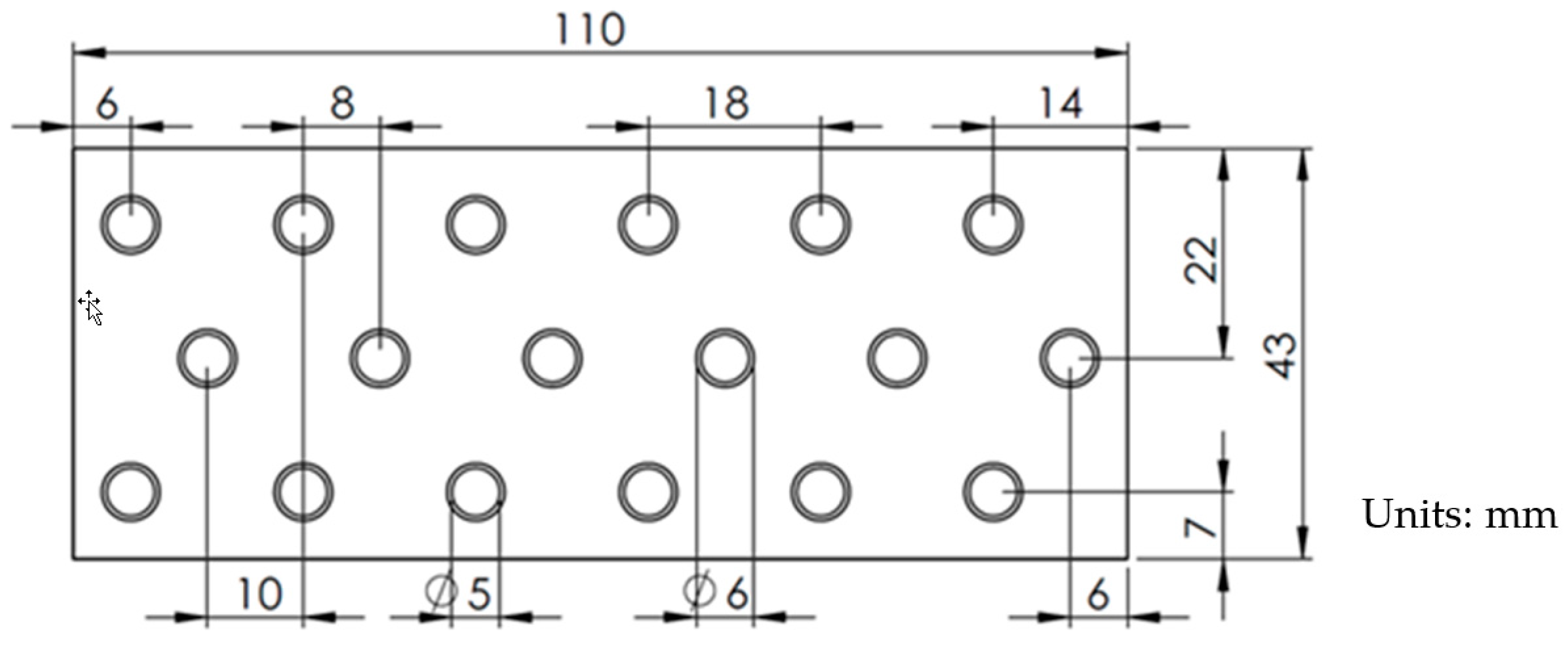
Figure 3.
The pulsating heat pipe heat exchanger in this study. (a) The schematic diagram, and (b) the actual one.
Figure 3.
The pulsating heat pipe heat exchanger in this study. (a) The schematic diagram, and (b) the actual one.

Figure 4.
Heat transfer rate of four heat exchangers possessing water-charged PHP, HFE-7000-charged PHP with and without degassing, and empty PHP versus the inlet temperature of the hot air with filling ratio of 35% at air velocity of (a) 0.5, and (b) 2.0 m/s.
Figure 4.
Heat transfer rate of four heat exchangers possessing water-charged PHP, HFE-7000-charged PHP with and without degassing, and empty PHP versus the inlet temperature of the hot air with filling ratio of 35% at air velocity of (a) 0.5, and (b) 2.0 m/s.
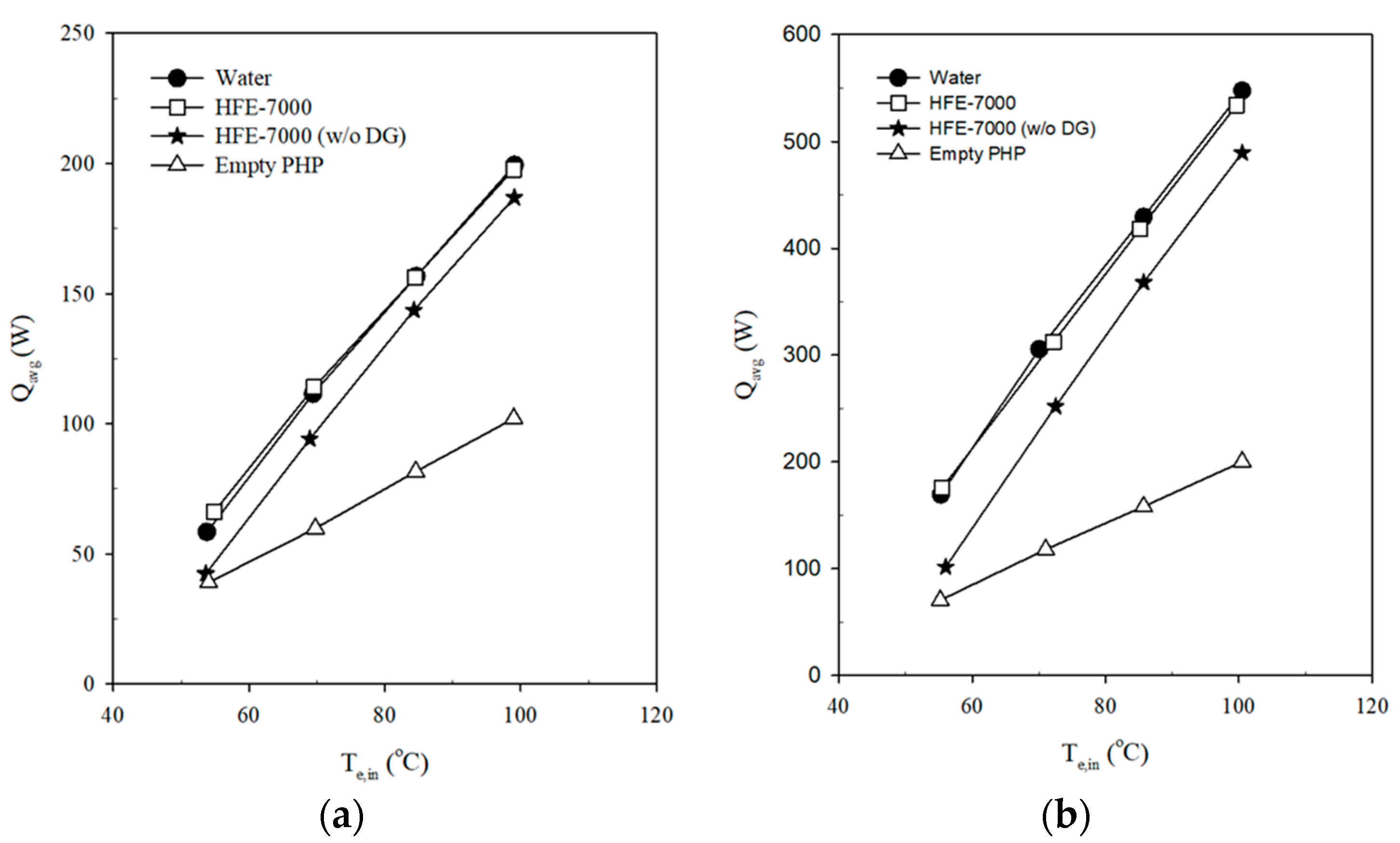
Figure 5.
Liquid-vapor saturation curve of water and HFE-7000.

Figure 6.
Variation of surface temperature in both evaporating section and condensing section of the PHP heat exchanger charged with (a) HFE-7000 after degassing, and (b) water, with time at hot air inlet temperatures stepwise increased from 55 to 100 °C with filling ratio of 35% at airflow velocity of 0.5 m/s.
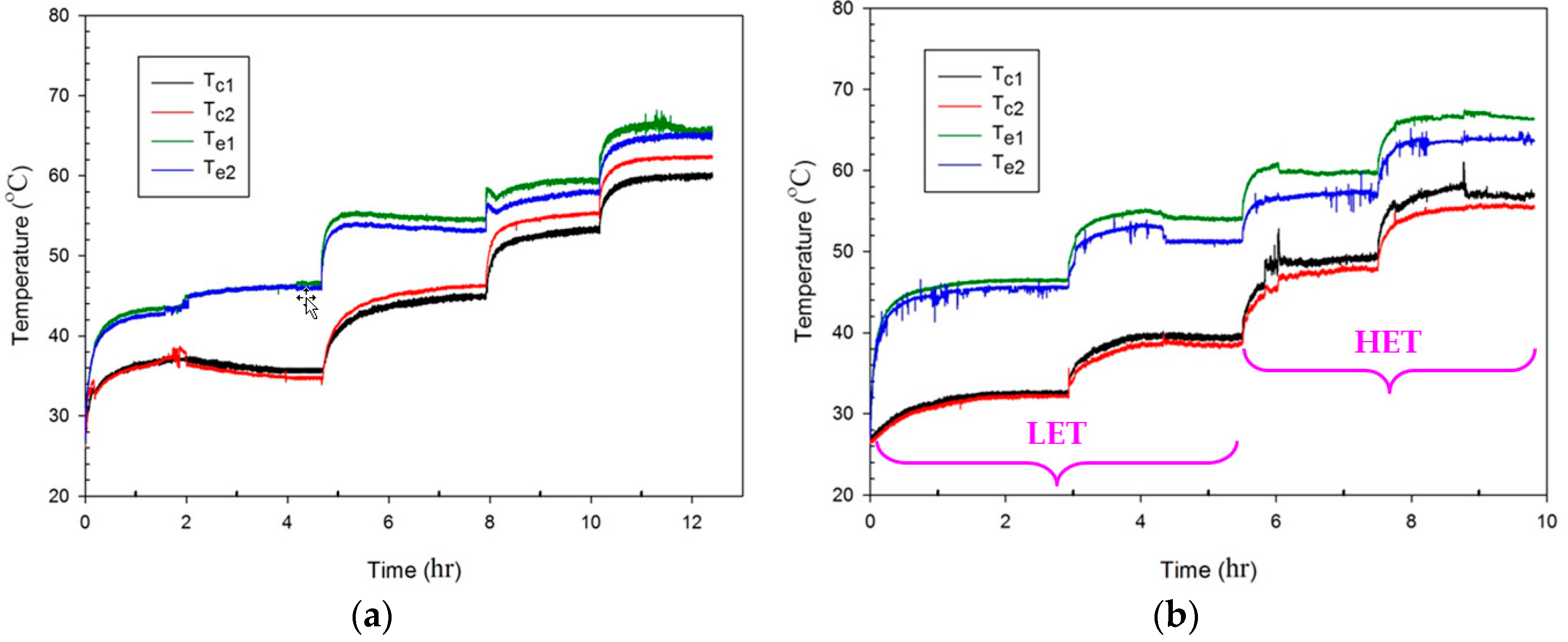
Figure 7.
Resistance of the PHPs charged with water and HFE-7000 in the filling ratio of 35% and 50% at various evaporator temperatures at airflow velocity of 0.5 m/s.
Figure 7.
Resistance of the PHPs charged with water and HFE-7000 in the filling ratio of 35% and 50% at various evaporator temperatures at airflow velocity of 0.5 m/s.

Figure 8.
The effectiveness of the heat exchangers possessing a (a) HFE-7000-charged PHP, (b) water-charged PHP, and (c) HFE-7000-charged PHP without degassing, versus the evaporator temperature with filling ratio of 35% at airflow velocity ranging from 0.5 to 2.0 m/s.
Figure 8.
The effectiveness of the heat exchangers possessing a (a) HFE-7000-charged PHP, (b) water-charged PHP, and (c) HFE-7000-charged PHP without degassing, versus the evaporator temperature with filling ratio of 35% at airflow velocity ranging from 0.5 to 2.0 m/s.
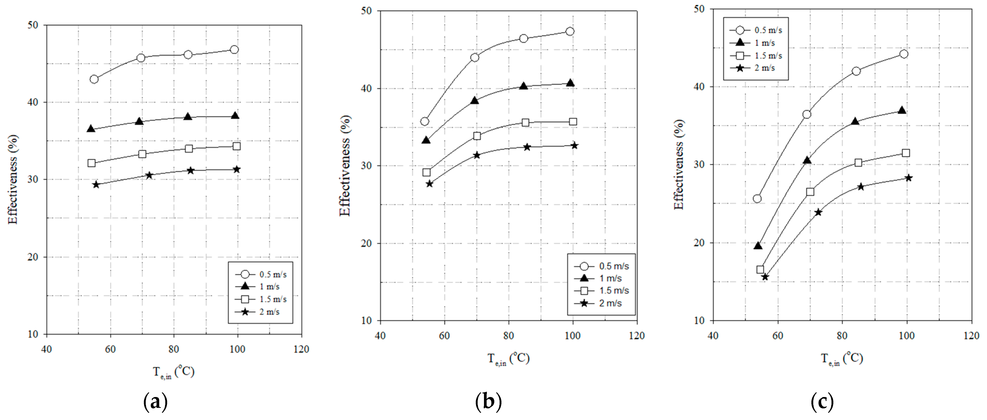
Figure 9.
For water-charged PHP heat exchanger with filling ratio of 50% at airflow velocity ranging from 0.5 to 2.0 m/s, the (a) variation of surface temperature in both evaporating and condensing sections with time at hot air inlet temperatures stepwise increased from 55 to 100 °C, and (b) effectiveness versus the evaporator temperature.

Figure 10.
For HFE-7000-charged PHP heat exchanger with filling ratio of 50% at airflow velocity ranging from 0.5 to 2.0 m/s, the (a) variation of surface temperature in both evaporating section and condensing section of the with time at hot air inlet temperatures stepwise increased from 55 to 100 °C, and (b) effectiveness versus the evaporator temperature.


Table 1.
Uncertainty of the average heat transfer rate and effectiveness of the heat exchangers.
| Conditions | Uncertainty | |||
|---|---|---|---|---|
| Effectiveness | ||||
| 35% water-charged | 55~100 °C | 0.5 m/s | 3.01% | 4.25% |
| 1.0 m/s | 2.97% | 4.22% | ||
| 1.5 m/s | 3.01% | 4.25% | ||
| 2.0 m/s | 3.01% | 4.25% | ||
| 35% HFE-7000-charged | 55~100 °C | 0.5 m/s | 3.01% | 4.25% |
| 1.0 m/s | 2.93% | 4.14% | ||
| 1.5 m/s | 3.00% | 4.25% | ||
| 2.0 m/s | 3.00% | 4.24% | ||
| 35% HFE-7000-charged w/o degassing | 55~100 °C | 0.5 m/s | 3.00% | 4.25% |
| 1.0 m/s | 2.97% | 4.22% | ||
| 1.5 m/s | 3.01% | 4.25% | ||
| 2.0 m/s | 3.00% | 4.24% | ||
| 50% water-charged | 55~100 °C | 0.5 m/s | 3.01% | 4.25% |
| 1.0 m/s | 3.00% | 4.19% | ||
| 1.5 m/s | 3.01% | 4.26% | ||
| 2.0 m/s | 3.01% | 4.25% | ||
| 50% HFE-7000-charged | 55~100 °C | 0.5 m/s | 3.01% | 4.25% |
| 1.0 m/s | 2.98% | 4.26% | ||
| 1.5 m/s | 3.01% | 4.25% | ||
| 2.0 m/s | 3.00% | 4.24% | ||
| 50% HFE-7000-charged w/o degassing | 55~100 °C | 0.5 m/s | 3.00% | 4.25% |
| 1.0 m/s | 2.98% | 4.26% | ||
| 1.5 m/s | 3.01% | 4.25% | ||
| 2.0 m/s | 3.00% | 4.24% | ||
Table 2.
Thermophysical properties of the working fluid at 75 °C unless otherwise specified.
| Parameter | 3M™ Novec™ 7000 (HFE-7000) | Water |
|---|---|---|
| Chemical formula | C3F3OCH3 | H2O |
| Boiling point @1 atm (°C) | 34 | 100 |
| Saturation pressure (kPa) | 364.3 | 38.6 |
| Liquid density, (kg/m3) | 1254 | 974.8 |
| Vapor density, (kg/m3) | 29.28 | 0.2422 |
| Liquid kinematic viscosity, ν (m2/s) | 2.378 × 10⁻⁷ | 3.875 × 10⁻⁷ |
| Liquid specific heat, Cp (kJ/kg·°C) | 1.331 | 4.193 |
| Liquid thermal conductivity, k (W/m·°C) | 0.065 | 0.668 |
| Latent heat of vaporization, hfg (kJ/kg) | 114.9 | 2321 |
| Liquid surface tension, σ (N/m) | 7.123 × 10⁻³ | 6.358 × 10⁻² |
Table 3.
PHP thermal resistance extracted from selected literature with vertical bottom heat mode.
| Item | Tube Length (L) | Working Fluid | Filling Ratio | Thermal Resistance | |
|---|---|---|---|---|---|
| Authors | Tube Diameter (ID, DH) | ||||
| Khandekar et al. [14] | L: 150 mm, ID: 2 mm | Water | 60% | 3.4~1.5 °C/W (5–55 W) | |
| Ethanol | 55% | 3.3~0.6 °C/W (5–55 W) | |||
| R-123 | 50% | 1.6~1.4 °C/W (5–23 W) | |||
| Wilson et al. [21] | L: 155 mm, ID: 1.65 mm | Water | 51% | 0.09~0.02 °C/W (45–300 W) | |
| Acetone | 48% | 0.105~0.04 °C/W (20–100 W) | |||
| Chien et al. [22] | L: 104 mm, DH: 2 mm | Distilled water | 70% | 1.5~0.6 °C/W (30–130 W) | |
| Qu et al. [27] | L: 46 mm, DH: 394 µm (silicon-based) | FC-72 | 47% | 8.5~5.2 °C/W (3–9 W) | |
| Qu et al. [27] | L: 46 mm, DH: 352 µm (silicon-based) | FC-72 | 55% | 9.5~5.5 °C/W (4–11 W) | |
| R-113 | 53% | 9.5~5 °C/W (4 – 9 W) | |||
| Tseng et al. [25] | L: 200 mm, ID: 2.4 mm | Water | 59.7% | 4~0.03 °C/W (20–140 W) | |
| Methanol | 59.8% | 2~0.06 °C/W (20–140 W) | |||
| HFE-7100 | 62.4% | 0.7~0.15 °C/W (20–140 W) | |||
| Sun et al. [33] | L: 200 mm, ID: 1.6 mm | Water | 50% | 0.928 °C/W (80 W) | |
| HFE-7000 | 50% | 1.161 °C/W (80 W) | |||
© 2020 by the authors. Licensee MDPI, Basel, Switzerland. This article is an open access article distributed under the terms and conditions of the Creative Commons Attribution (CC BY) license (http://creativecommons.org/licenses/by/4.0/).
Share and Cite
MDPI and ACS Style
Yang, K.-S.; Jiang, M.-Y.; Tseng, C.-Y.; Wu, S.-K.; Shyu, J.-C. Experimental Investigation on the Thermal Performance of Pulsating Heat Pipe Heat Exchangers. Energies 2020, 13, 269. https://doi.org/10.3390/en13010269
AMA Style
Yang K-S, Jiang M-Y, Tseng C-Y, Wu S-K, Shyu J-C. Experimental Investigation on the Thermal Performance of Pulsating Heat Pipe Heat Exchangers. Energies. 2020; 13(1):269. https://doi.org/10.3390/en13010269
Chicago/Turabian StyleYang, Kai-Shing, Ming-Yean Jiang, Chih-Yung Tseng, Shih-Kuo Wu, and Jin-Cherng Shyu. 2020. "Experimental Investigation on the Thermal Performance of Pulsating Heat Pipe Heat Exchangers" Energies 13, no. 1: 269. https://doi.org/10.3390/en13010269
Note that from the first issue of 2016, this journal uses article numbers instead of page numbers. See further details here.