Characteristics of Roof Ground Subsidence While Applying a Continuous Excavation Continuous Backfill Method in Longwall Mining


Abstract
:
1. Introduction
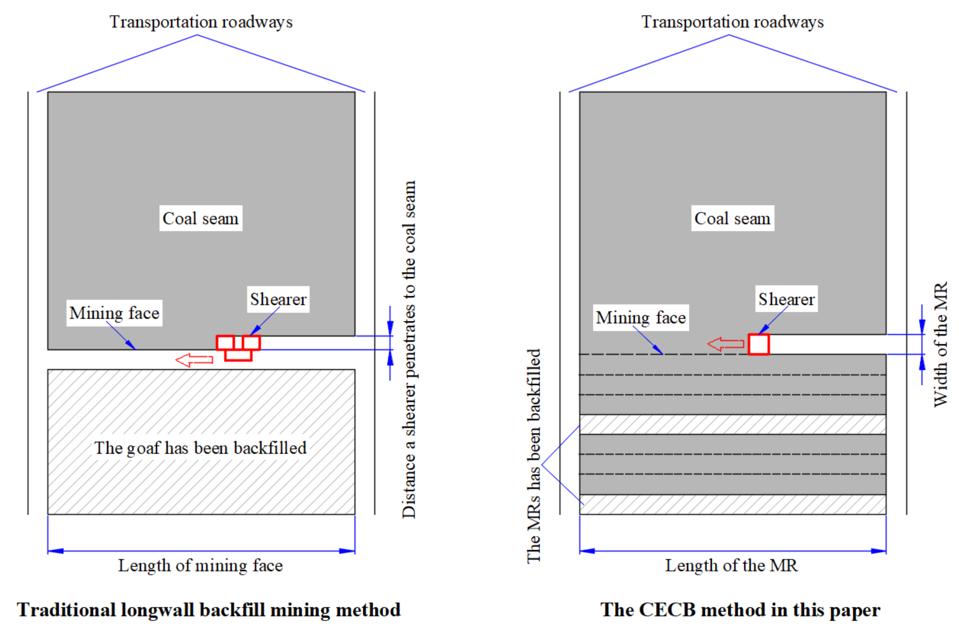
2. The CECB Method
2.1. Geologic Conditions
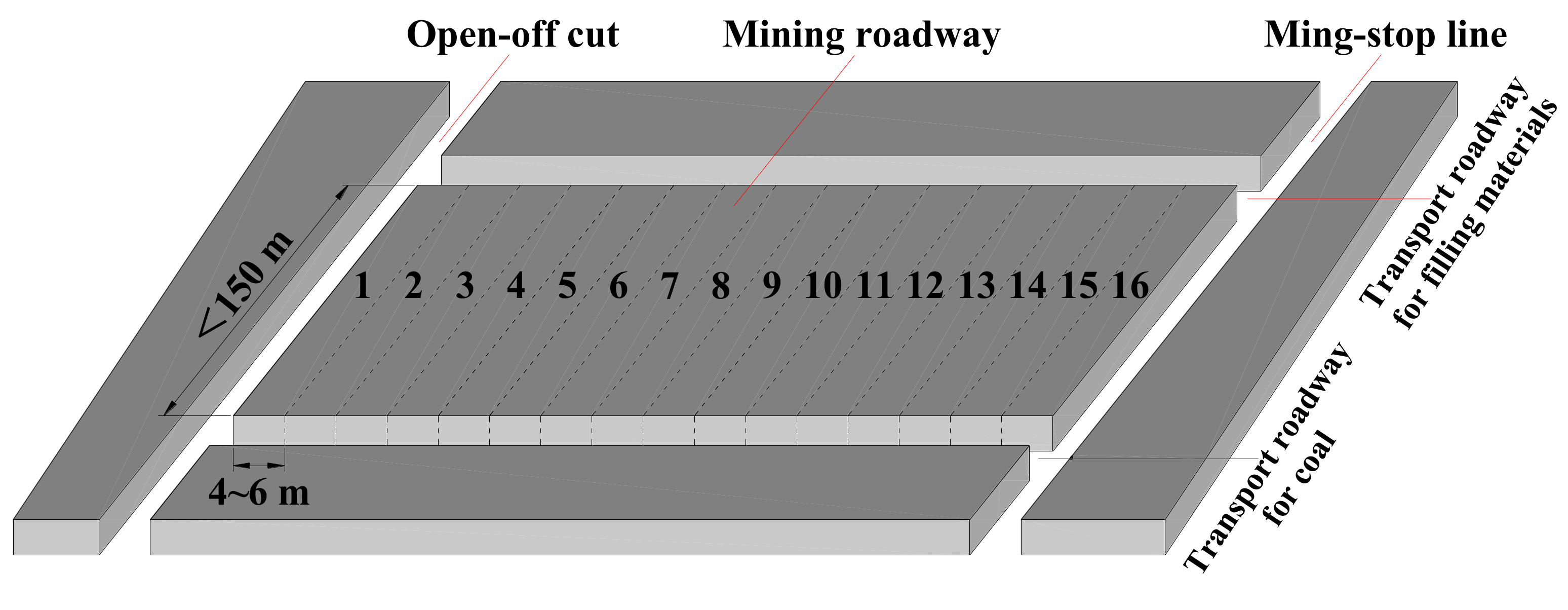
2.2. Arrangement of the Mining Panel
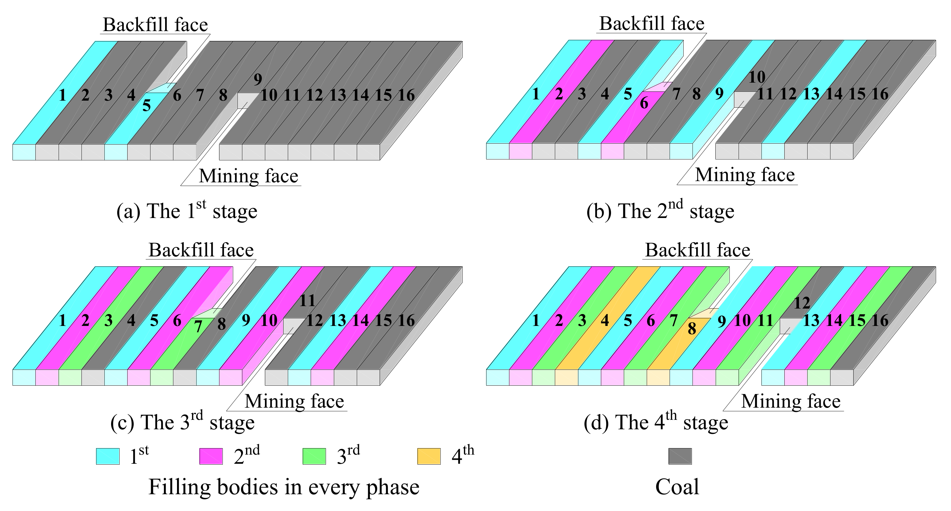
2.3. Mining Procedures
3. Mechanical Mechanism of Roof Sinking
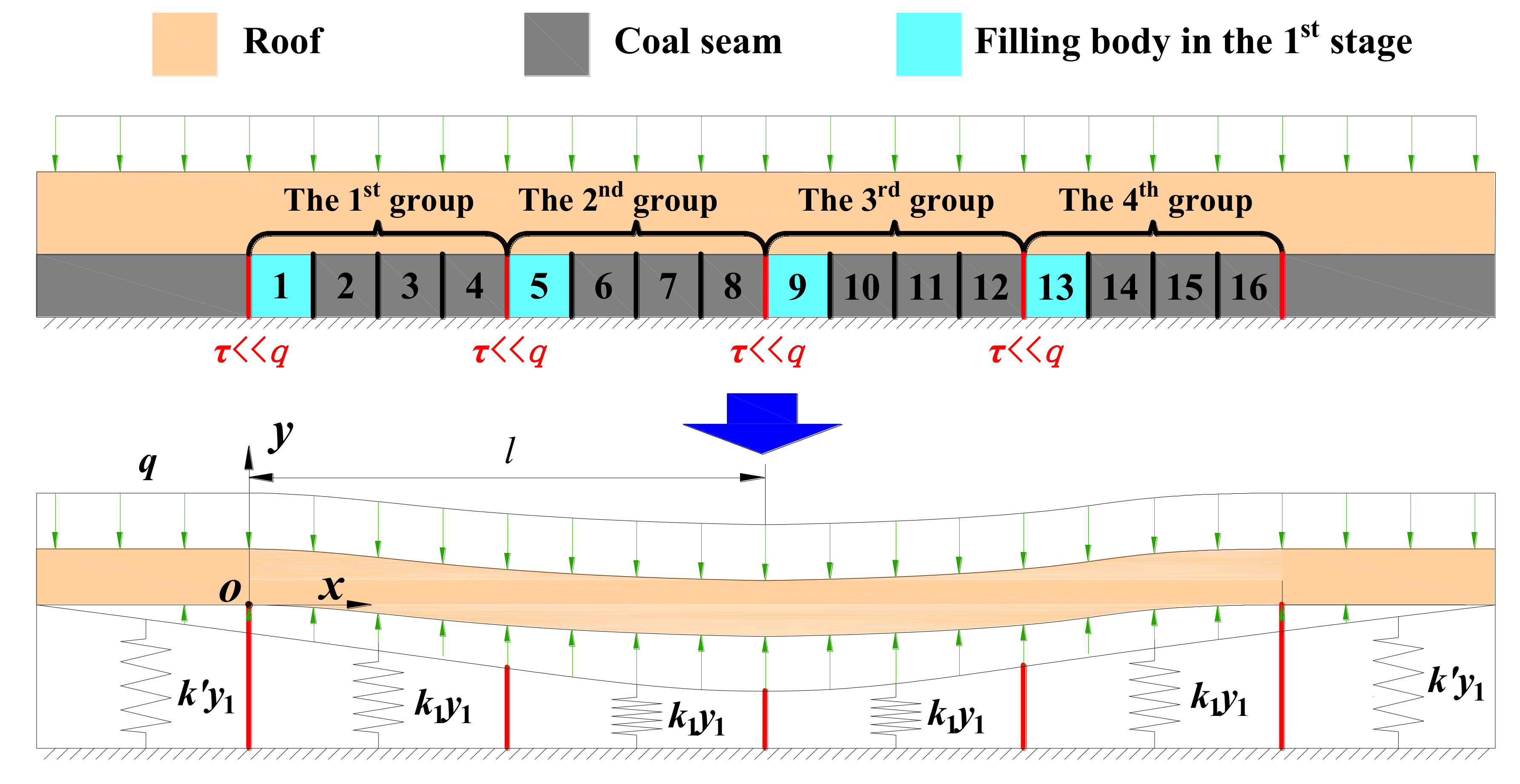
3.1. Mechanical Model
3.2. Elastic Foundation Coefficient
3.2.1. The Foundation Coefficient in the First Stage
3.2.2. The Foundation Coefficient in the Second Stage
3.2.3. The Foundation Coefficient in the Third Stage
3.2.4. The Foundation Coefficient in the Fourth Stage
4. Subsidence of the Roof and the Ground
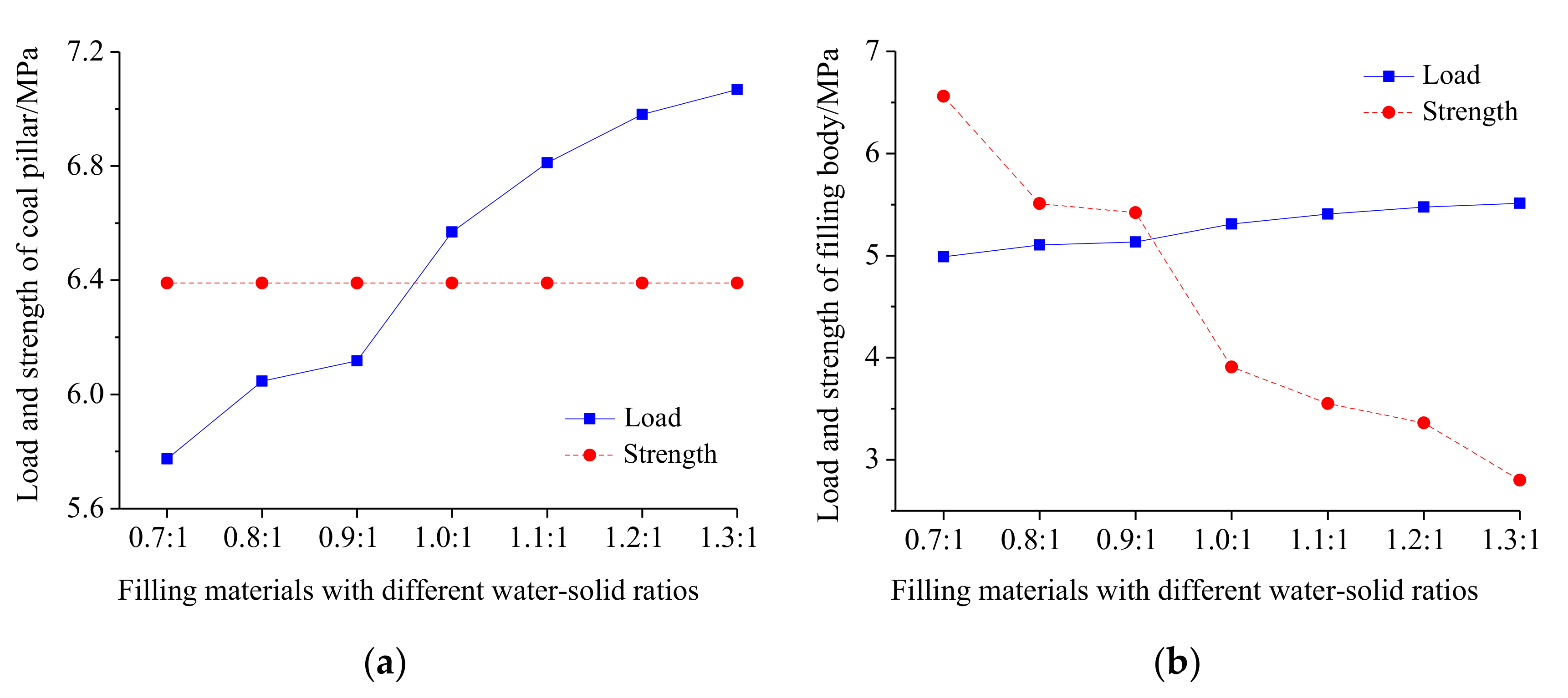
4.1. The Stability of the Coal Pillar
4.2. The Stability of the Filling Body
4.3. Parameters of Filling Materials
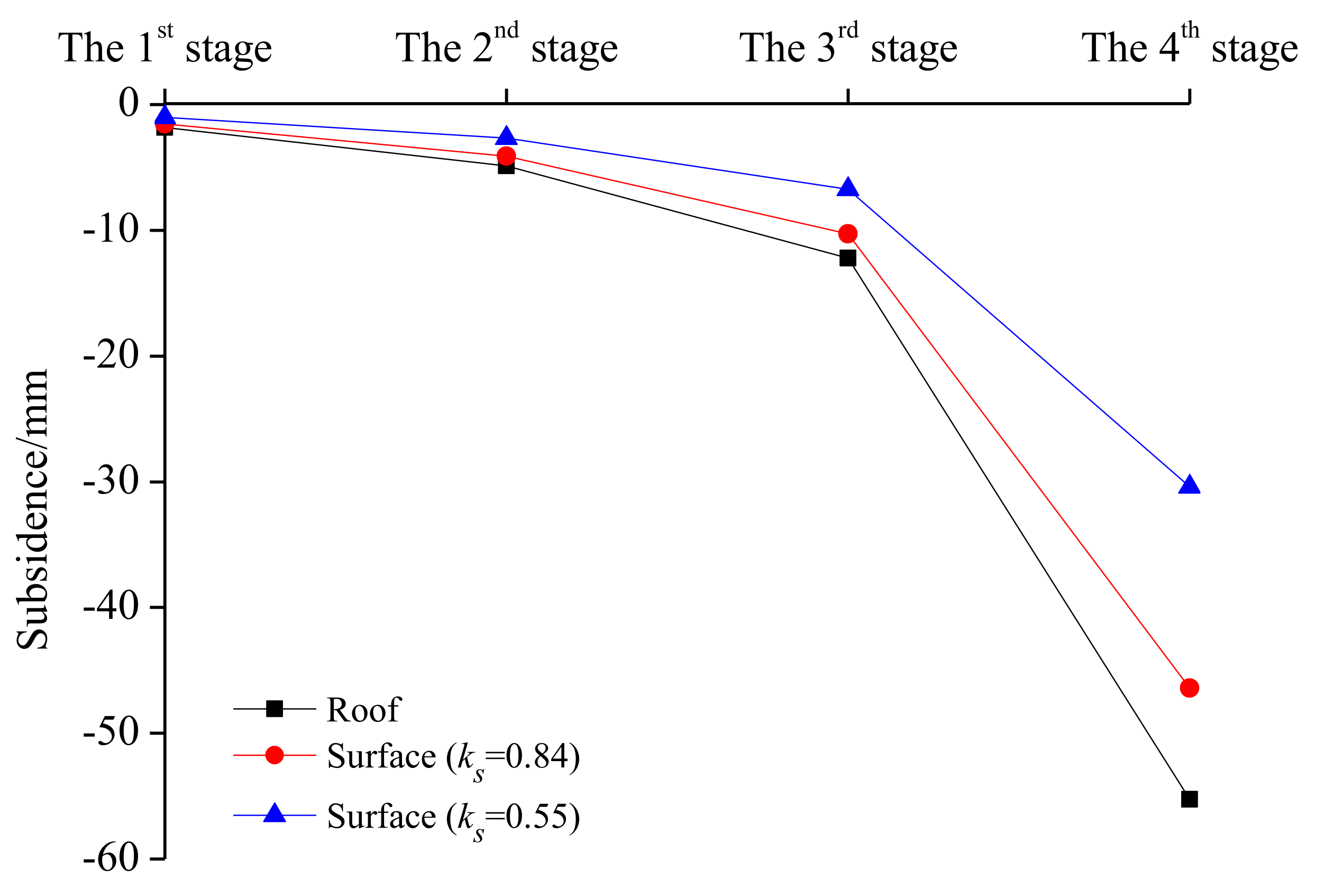
4.4. The Roof and Ground Subsidence in Every Stage
5. Numerical Simulation on the Ground Subsidence Induced by Mining
5.1. Numerical Model
5.2. Simulation Process
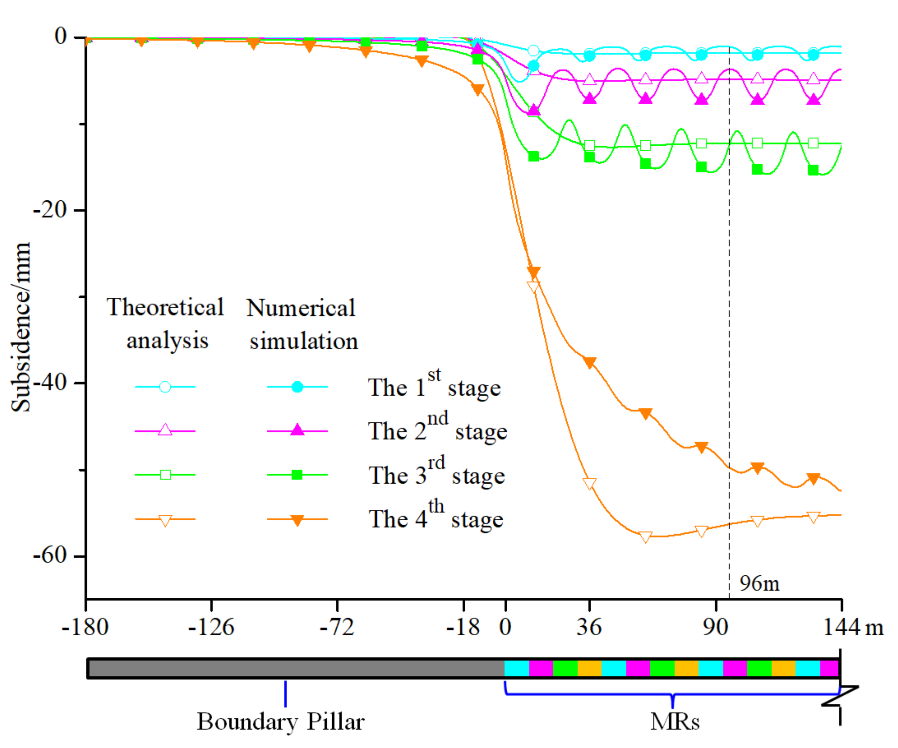
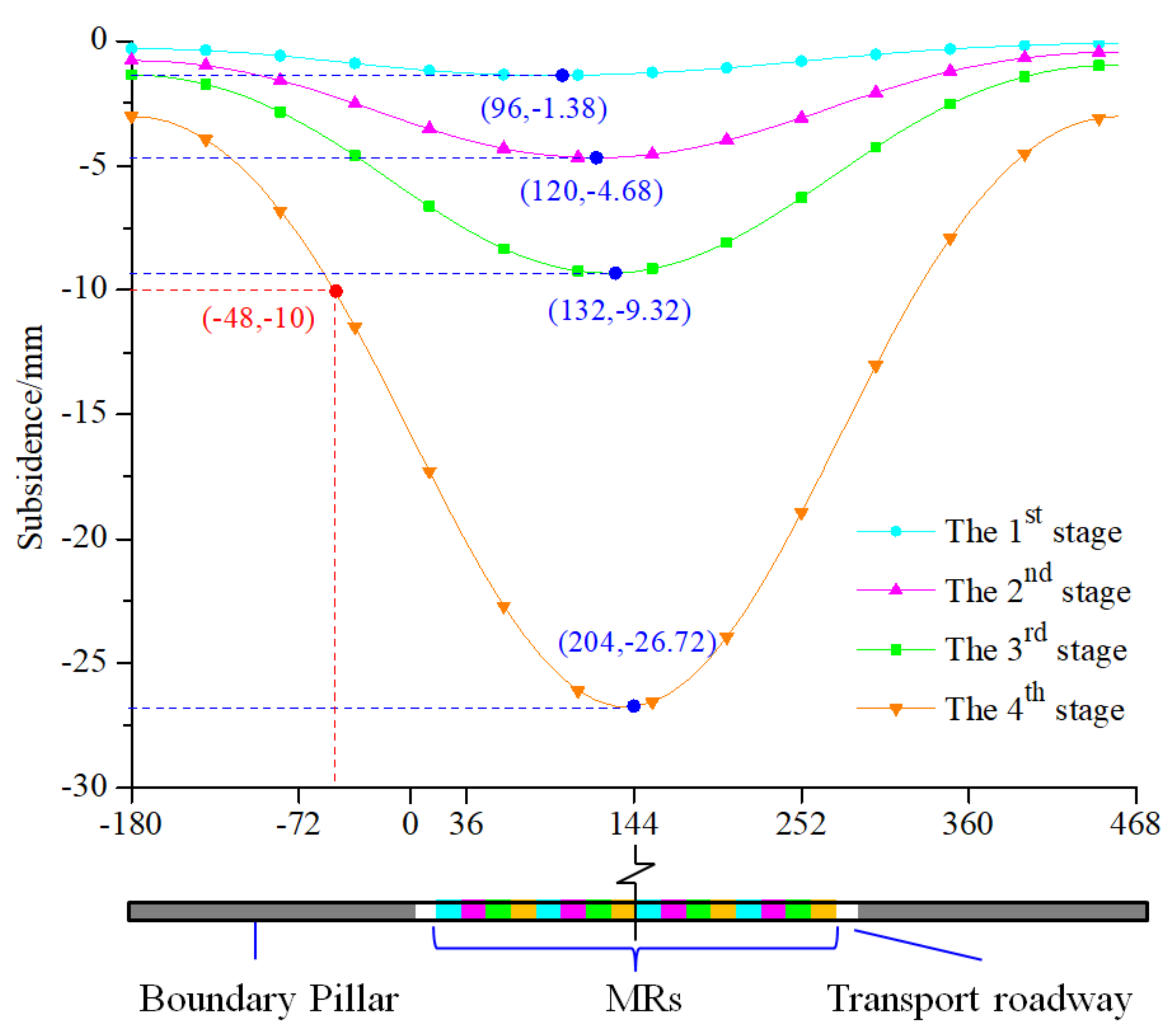
5.3. Roof Subsidence
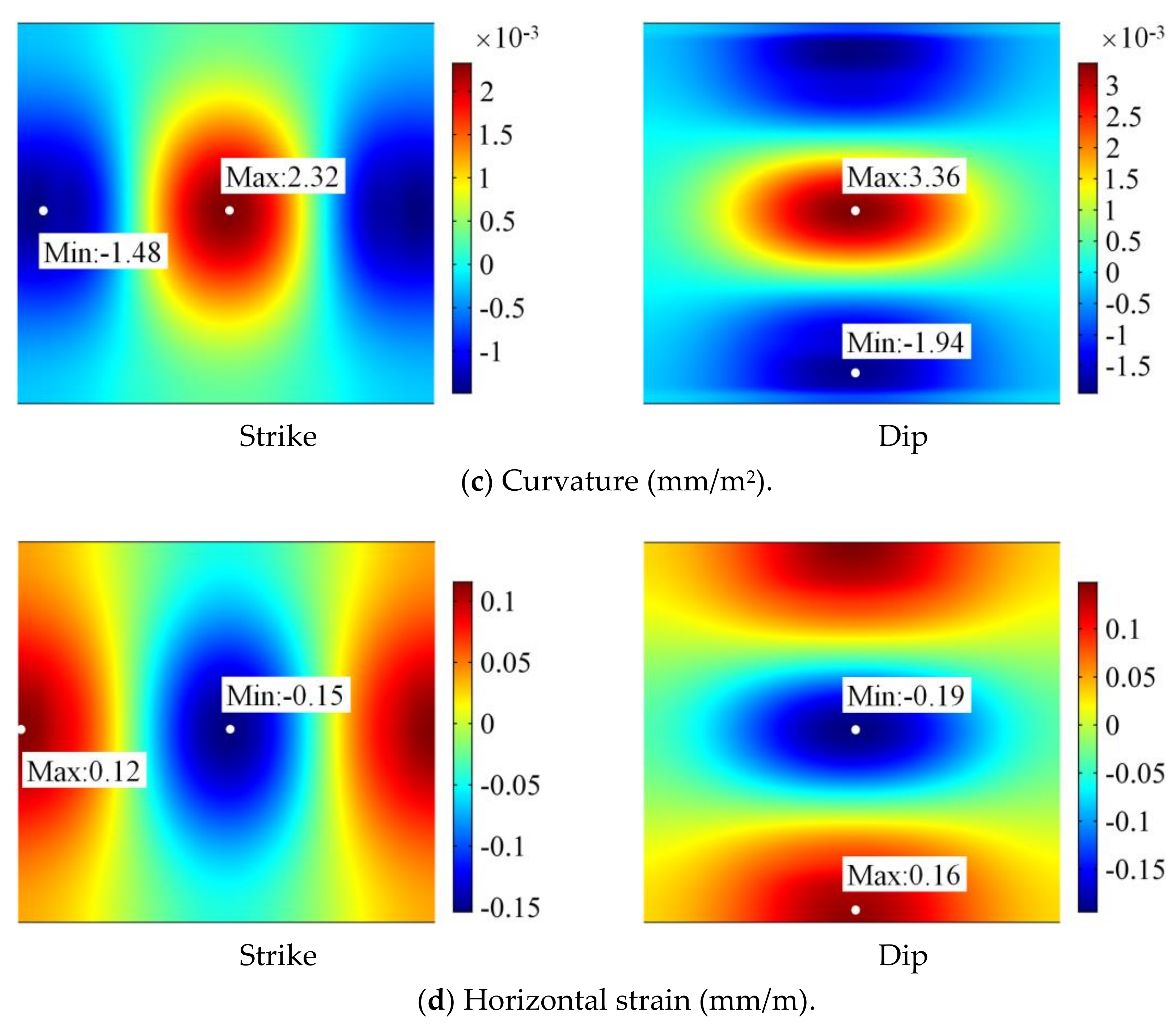
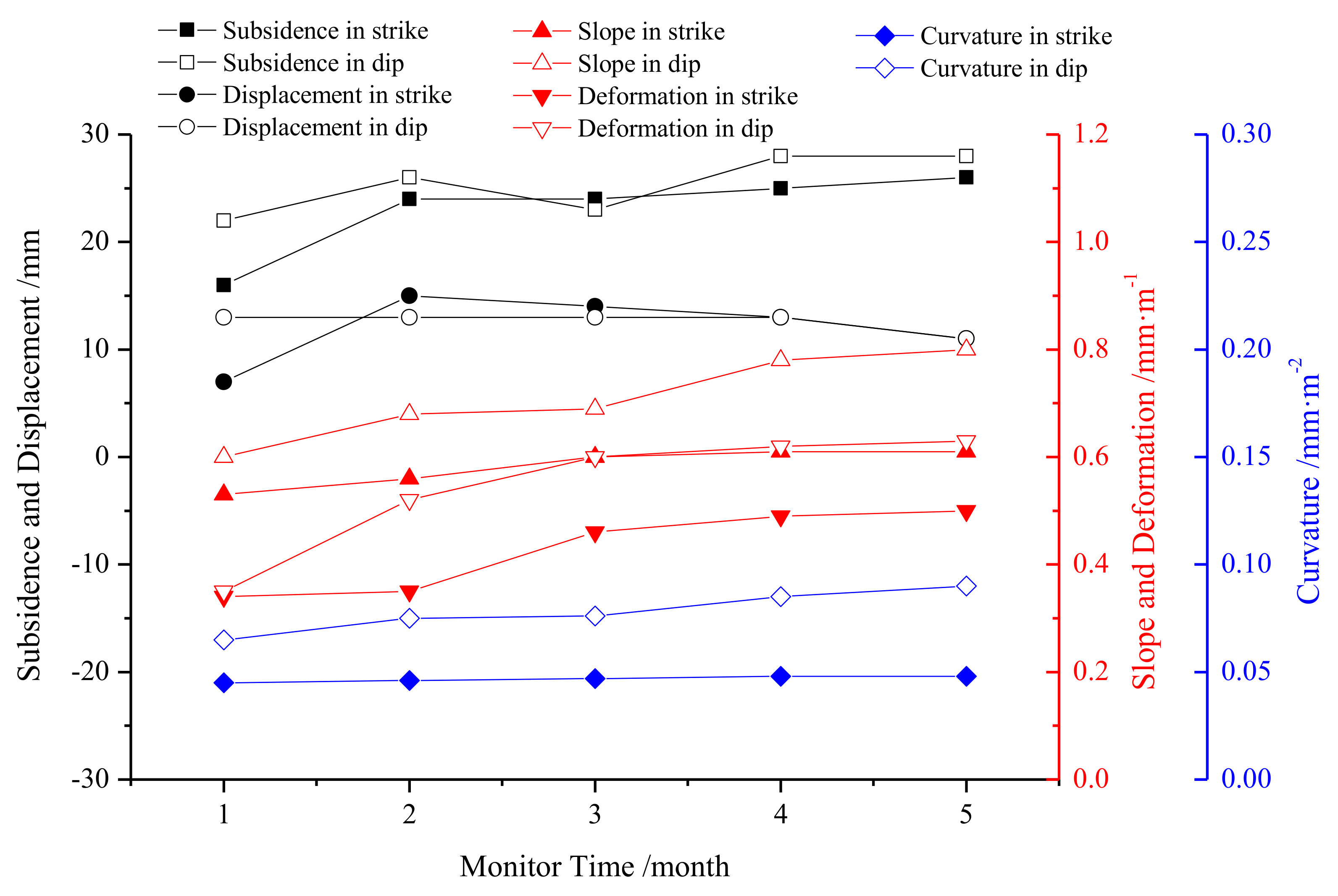
5.4. Ground Subsidence and Deformation
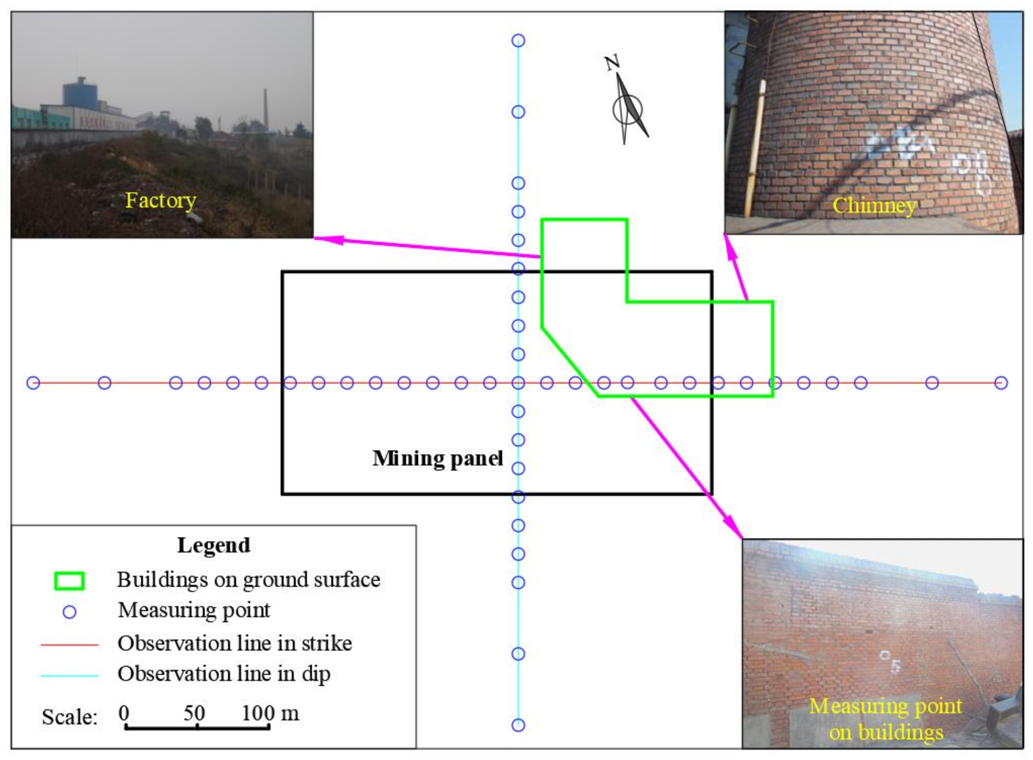
6. Field Practice
7. Discussion
8. Conclusions
Author Contributions
Funding
Conflicts of Interest
References
- Guo, J.S.; Ma, L.Q.; Zhang, D.S. Management and utilization of high-pressure floor-confined water in deep coal mines. Mine Water Environ. 2019, 38, 780–797. [Google Scholar] [CrossRef]
- Lian, X.; Dai, H. Mapping the degree of damage to houses of Paifang village, Anhui, China, caused by underground coal extraction. Water Air Soil Pollut. 2016, 75, 182. [Google Scholar] [CrossRef]
- Dontala, S.P.; Reddy, T.B.; Vadde, R. Environmental aspects and impacts its mitigation measures of corporate coal mining. Procedia Earth Planet. Sci. 2015, 11, 2–7. [Google Scholar] [CrossRef] [Green Version]
- Ng, A.H.-M.; Chang, H.-C.; Ge, L.; Rizos, C.; Omura, M. Assessment of radar interferometry performance for ground subsidence monitoring due to underground mining. Earth Planets Space 2009, 61, 733–745. [Google Scholar] [CrossRef] [Green Version]
- Ishwar, S.G.; Kumar, D. Application of DInSAR in mine surface subsidence monitoring and prediction. Curr. Sci. 2017, 112, 46–51. [Google Scholar] [CrossRef]
- Lokhande, R.D.; Prakash, A.; Singh, K.B.; Singh, K.K.K. Subsidence control measures in coalmines: A review. J. Sci. Ind. Res. 2005, 64, 323–332. [Google Scholar]
- Diao, X.; Bai, Z.; Wu, K.; Zhou, D.; Li, Z. Assessment of mining-induced damage to structures using InSAR time series analysis: A case study of Jiulong Mine, China. Environ. Earth Sci. 2018, 77, 166. [Google Scholar] [CrossRef]
- Li, Q.F. Challenging combination of CO2 geological storage and coal mining in the Ordos basin, China. Greenh. Gases Sci. Technol. 2014, 4, 452–467. [Google Scholar] [CrossRef]
- Booth, C.J. Confined-unconfined changes above longwall coal mining due to increases in fracture porosity. Environ. Eng. Geosci. 2007, 13, 355–367. [Google Scholar] [CrossRef]
- Booth, C.J. Groundwater as an environmental constraint of longwall coal mining. Environ. Geol. 2006, 49, 796–803. [Google Scholar] [CrossRef]
- Altun, A.O.; Yilmaz, I.; Yildirim, M. A short review on the surficial impacts of underground mining. Sci. Res. Essays 2010, 5, 3206–3212. [Google Scholar]
- Ng, A.H.-M.; Ge, L.; Yan, Y.; Li, X.; Chang, H.-C.; Zhang, K.; Rizos, C. Mapping accumulated mine subsidence using small stack of SAR differential interferograms in the southern coalfield of New South Wales, Australia. Eng. Geol. 2010, 115, 1–15. [Google Scholar] [CrossRef]
- Ghabraie, B.; Ghabraie, K.; Ren, G.; Smith, J.V. Numerical modelling of multistage caving processes: insights from multi-seam longwall mining-induced subsidence. Int. J. Numer. Anal. Methods Geomech. 2017, 41, 959–975. [Google Scholar] [CrossRef]
- Scott, B.; Ranjtih, P.G.; Choi, S.K.; Khandelwal, M. Geological and geotechnical aspects of underground coal mining methods within Australia. Environ. Earth Sci. 2010, 60, 1007–1019. [Google Scholar] [CrossRef]
- Guo, Z.; Li, J.; Li, C.; Ge, H. Short wall box style mining method of strip coal pillar under town. Appl. Mech. Mater 2011, 121–126, 4146–4150. [Google Scholar] [CrossRef]
- Yu, Y.; Chen, S.E.; Deng, K.Z.; Fan, H.D. Long-term stability evaluation and pillar design criterion for room-and-pillar mines. Energies 2017, 10, 1644. [Google Scholar] [CrossRef] [Green Version]
- Mathey, M. Modelling coal pillar stability from mine survey plans in a geographic information system. J. South. Afr. Inst. Min. Metall. 2018, 118, 157–164. [Google Scholar] [CrossRef] [Green Version]
- Van der Merwe, J.N. A three-tier method of stability evaluation for coal mines in the witbank and highveld coalfields. J. South. Afr. Inst. Min. Metall. 2016, 116, 1189–1194. [Google Scholar] [CrossRef] [Green Version]
- Yu, Y.; Deng, K.Z.; Luo, Y.; Chen, S.E.; Zhuang, H.F. An improved method for long-term stability evaluation of strip mining and pillar design. Int. J. Rock Mech. Min. Sci. 2018, 107, 25–30. [Google Scholar] [CrossRef]
- Liu, Z.X.; Luo, T.; Li, X.; Li, X.B.; Huai, Z.; Wang, S.F. Construction of reasonable pillar group for undersea mining in metal mine. Trans. Nonferrous Met. Soc. China. 2018, 28, 757–765. [Google Scholar] [CrossRef]
- Zhou, N.; Zhang, J.; Yan, H.; Li, M. Deformation behavior of hard roofs in solid backfill coal mining using physical models. Energies 2017, 10, 557. [Google Scholar] [CrossRef] [Green Version]
- Huang, Y.; Zhang, J.; Yin, W.; Sun, Q. Analysis of overlying strata movement and behaviors in caving and solid backfilling mixed coal mining. Energies 2017, 10, 1057. [Google Scholar] [CrossRef] [Green Version]
- Freidin, A.M.; Neverov, A.A.; Neverov, S.A. Geomechanical assessment of compound mining technology with backfilling and caving for thick flat ore bodies. J. Min. Sci. 2016, 52, 114–124. [Google Scholar] [CrossRef]
- Ma, L.Q.; Zhang, D.S.; Wang, S.K.; Xie, Y.S.; Yu, Y.H. Water-preserved mining with the method named “backfilling while mining”. J. China Coal Soc. 2018, 43, 62–69. [Google Scholar]
- Huang, Y.; Li, J.; Song, T.; Kong, G.; Li, M. Analysis on filling ratio and shield supporting pressure for overburden movement control in coal mining with compacted backfilling. Energies 2017, 10, 31. [Google Scholar] [CrossRef] [Green Version]
- Gong, P.; Ma, Z.; Zhang, R.R.; Ni, X.; Liu, F.; Huang, Z. Surrounding rock deformation mechanism and control technology for gob-side entry retaining with fully mechanized gangue backfilling mining: a case study. Shock Vib. 2017, 15, 6085941. [Google Scholar] [CrossRef] [Green Version]
- Zhang, J.; Li, B.; Zhou, N.; Zhang, Q. Application of solid backfilling to reduce hard-roof caving and longwall coal face burst potential. Int. J. Rock Mech. Min. Sci. 2016, 88, 197–205. [Google Scholar] [CrossRef]
- Ma, L.Q.; Xu, Y.J.; Zhang, D.S.; Lai, X.P.; Huang, K.J.; Dou, H.L. Characteristics of aquiclude and surface deformation in continuous mining and filling with wall system for water conservation. J. Min. Saf. Eng. 2019, 36, 30–36. [Google Scholar]
- Wang, S.K.; Ma, L.Q. Characteristics and control of mining induced fractures above longwall mines using backfilling. Energies 2019, 12, 4604. [Google Scholar] [CrossRef] [Green Version]
- Wang, A.; Ma, L.; Wang, Z.; Zhang, D.; Li, K.; Zhang, Y.; Yi, X. Soil and water conservation in mining area based on ground surface subsidence control: development of a high-water swelling material and its application in backfilling mining. Environ. Earth Sci. 2016, 75, 779. [Google Scholar] [CrossRef]
- Cao, Z.; Xu, P.; Li, Z.; Zhang, M.; Zhao, Y.; Shen, W. Joint bearing mechanism of coal pillar and backfilling body in roadway backfilling mining technology. CMC 2018, 54, 137–159. [Google Scholar]
- Wang, H.; Poulsen, B.A.; Shen, B.; Xue, S.; Jiang, Y. The influence of roadway backfill on the coal pillar strength by numerical investigation. Int. J. Rock Mech. Min. Sci. 2011, 48, 443–450. [Google Scholar] [CrossRef]
- Zhang, J.X.; Huang, P.; Zhang, Q.; Li, M.; Chen, Z.W. Stability and control of room mining coal pillars-taking room mining coal pillars of solid backfill recovery as an example. J. Cent. South Univ. 2017, 24, 1121–1132. [Google Scholar] [CrossRef]
- Zhang, J.X.; Sun, Q.; Zhou, N.; Jiang, H.; Germain, D.; Abro, S. Research and application of roadway backfill coal mining technology in western coal mining area. Arab. J. Geosci. 2016, 9, 558. [Google Scholar] [CrossRef]
- Li, H.Z.; Guo, G.L.; Zhai, S.C. Mining scheme design for super-high water backfill strip mining under buildings: A Chinese case study. Environ. Earth Sci. 2016, 75, 1017. [Google Scholar] [CrossRef]
- Zhou, N.; Li, M.; Zhang, J.X.; Gao, R. Roadway backfill method to prevent geohazards induced by room and pillar mining: a case study in Changxing coal mine, China. Nat. Hazards Earth Sys. Sci. 2016, 16, 2473–2484. [Google Scholar] [CrossRef]
- Liu, J.W.; Sui, W.H.; Zhao, Q.J. Environmentally sustainable mining: A case study of intermittent cut-and-fill mining under sand aquifers. Environ. Earth Sci. 2017, 76, 562. [Google Scholar] [CrossRef] [Green Version]
- Sun, Q.; Zhang, J.; Zhou, N. Study and discussion of short-strip coal pillar recovery with cemented paste backfill. International J. Rock Mech. Min. Sci. 2018, 104, 147–155. [Google Scholar] [CrossRef]
- Yu, Y.H.; Ma, L.Q. Application of roadway backfill mining in water-conservation coal mining: A case study in Northern Shaanxi, China. Sustainability 2019, 11, 3719. [Google Scholar] [CrossRef] [Green Version]
- Zhang, J.X.; Zhang, Q.; Sun, Q.; Gao, R.; Germain, D.; Abro, S. Surface subsidence control theory and application to backfill coal mining technology. Environ. Earth Sci. 2015, 74, 1439–1448. [Google Scholar] [CrossRef]
- Sobhy, M. Buckling and free vibration of exponentially graded sandwich plates resting on elastic foundations under various boundary conditions. Compos. Struct. 2013, 99, 76–87. [Google Scholar] [CrossRef]
- Poulsen, B.A.; Adhikary, D.P. A numerical study of the scale effect in coal strength. Int. J. Rock Mech. Min. Sci. 2013, 63, 62–71. [Google Scholar] [CrossRef]
- Choudhary, B.S.; Kumar, S. Underground void filling by cemented mill tailings. Int. J. Min. Sci. Tech. 2013, 23, 893–900. [Google Scholar] [CrossRef]
- Chen, S.; Yin, D.; Cao, F.; Yong, L.; Ren, K. An overview of integrated surface subsidence-reducing technology in mining areas of china. Nat. Hazards 2016, 81, 1129–1145. [Google Scholar] [CrossRef]
- Guo, G.L.; Zhu, X.J.; Zha, J.F.; Wang, Q. Subsidence prediction method based on equivalent mining height theory for solid backfilling mining. Trans. Nonferrous Met. Soc. China 2014, 24, 3302–3308. [Google Scholar] [CrossRef]
- Zhu, X.; Guo, G.; Zha, J.; Chen, T.; Fang, Q.; Yang, X. Surface dynamic subsidence prediction model of solid backfill mining. Environ. Earth Sci. 2016, 75, 1007. [Google Scholar] [CrossRef]
- Sun, Q.; Zhang, J.X.; Zhou, N.; Qi, W. Roadway backfill coal mining to preserve surface water in western China. Min. Wat. Environ. 2018, 37, 366–375. [Google Scholar] [CrossRef]
- Fan, H.D.; Gao, X.D.; Yang, J.K.; Deng, K.Z.; Yu, Y. Monitoring mining subsidence using a combination of phase-stacking and offset-tracking methods. Remote Sens. 2015, 7, 9166–9183. [Google Scholar] [CrossRef] [Green Version]
- Ding, R.; Liu, H.; Yuan, G.; Dong, J. Deformation and subsidence prediction on surface of Yuzhou mined-out areas along middle route project of south-to-north water diversion, China. Open Geosci. 2018, 10, 834–843. [Google Scholar]
- Blachowski, J.; Chrzanowski, A.; Szostak-Chrzanowski, A. Application of GIS methods in assessing effects of mining activity on surface infrastructure. Arch. Min. Sci. 2014, 59, 307–321. [Google Scholar]


| Water–solid ratios | 0.7:1 | 0.8:1 | 0.9:1 | 1.0:1 | 1.1:1 | 1.2:1 | 1.3:1 |
| Elastic modulus of filling materials (Ef)/GPa | 0.29 | 0.25 | 0.24 | 0.18 | 0.15 | 0.13 | 0.12 |
| Mining Height (h)/m | Bury Depth of Coal Seam (H)/m | Width of the MR (w)/m | Length of the Panel (2l)/m | Elastic Modulus of the Roof (E)/GPa | Average Bulk Density of Strata (γ)/kN·m-3 | Elastic Modulus of the Coal (Ec)/GPa |
|---|---|---|---|---|---|---|
| 2.5 | 219.5 | 6 | 288 | 13.2 | 20.3 | 2.0 |
| Lithology | Bulk Modulus/GPa | Shear Modulus/GPa | Cohesion/MPa | Internal Friction Angle/° | Tensile Strength/MPa | Bulk Density /kN·m3 |
|---|---|---|---|---|---|---|
| Loess | 0.06 | 0.04 | 0.12 | 24 | 0.08 | 14.7 |
| Red clay | 0.08 | 0.05 | 0.33 | 27 | 0.12 | 19.7 |
| Medium sandstone | 3.2 | 2.0 | 1.6 | 31 | 1.4 | 20.6 |
| Sandy mudstone | 2.8 | 1.7 | 1 | 22 | 1 | 19.7 |
| Mudstone | 2.9 | 2.1 | 1.4 | 19 | 1.1 | 28.6 |
| Sandy mudstone | 3.0 | 1.8 | 3.0 | 1.8 | 3.0 | 22.4 |
| Fine sandstone | 3.8 | 2.6 | 1.6 | 31 | 1.4 | 20.6 |
| Limestone | 7.2 | 5.5 | 2 | 40 | 4.0 | 24.0 |
| Sandy mudstone | 3.0 | 1.8 | 1 | 20 | 1 | 19.8 |
| Limestone | 7.2 | 5.5 | 2 | 40 | 4.0 | 24.0 |
| Coal/filling body | 2.2/0.14 | 0.76/0.1 | 1/0.24 | 20/36 | 1/0.19 | 18.7/18.0 |
| Bauxitic mudstone | 4.2 | 2.8 | 1.4 | 34 | 1.4 | 28.6 |
© 2019 by the authors. Licensee MDPI, Basel, Switzerland. This article is an open access article distributed under the terms and conditions of the Creative Commons Attribution (CC BY) license (http://creativecommons.org/licenses/by/4.0/).
Share and Cite
Yu, Y.; Ma, L.; Zhang, D. Characteristics of Roof Ground Subsidence While Applying a Continuous Excavation Continuous Backfill Method in Longwall Mining. Energies 2020, 13, 95. https://doi.org/10.3390/en13010095
Yu Y, Ma L, Zhang D. Characteristics of Roof Ground Subsidence While Applying a Continuous Excavation Continuous Backfill Method in Longwall Mining. Energies. 2020; 13(1):95. https://doi.org/10.3390/en13010095
Chicago/Turabian StyleYu, Yihe, Liqiang Ma, and Dongsheng Zhang. 2020. "Characteristics of Roof Ground Subsidence While Applying a Continuous Excavation Continuous Backfill Method in Longwall Mining" Energies 13, no. 1: 95. https://doi.org/10.3390/en13010095