Article

Study on the Failure Mechanism for Coal Roadway Stability in Jointed Rock Mass Due to the Excavation Unloading Effect

1
Institute of Mining Research, Inner Mongolia University of Science and Technology, Baotou 014010, China
2
State Key Laboratory for Geomechanics & Deep Underground Engineering, China University of Mining & Technology, Beijing 100083, China
3
Inner Mongolia Key Laboratory of Mining Pressure and Strata Control, Hulunbuir University, Hulunbuir 021008, China
*
Author to whom correspondence should be addressed.
Energies 2020, 13(10), 2515; https://doi.org/10.3390/en13102515
Submission received: 31 March 2020 / Revised: 2 May 2020 / Accepted: 9 May 2020 / Published: 15 May 2020

Abstract

:
Aiming at the large deformation instability problem caused by the excavation unloading of a coal roadway in deep-buried slowly inclined jointed rock mass, the geomechanical parameters and deformation failure characteristics of an engineering geomechanical model were investigated. The in-situ stress state of the model was measured with the stress relief method. The geological and mechanical properties of roadway surrounding rock were described. The surrounding rock structure was revealed with the electron microscopy scanning method, micro-fractures and randomly distributed joints highly developed in roadway surrounding rock. Field investigation and monitoring indicated the cross-section of roadway surrounding rock shrank continuously and the deformation distribution was obviously asymmetric. Shotcrete spalling and cable broken failures frequently occurred in the middle and ride side of roof and right rib. Based on the geomechanical conditions of the coal roadway, a discrete element numerical model of coal roadway in gently inclined jointed rock mass was established. The parameters of rock mass in the numerical model were calibrated. The model ran in unsupported condition to restore the evolution process of stress, crack propagation and deformation in roadway surrounding rock due to gradual deviatoric stress release caused by excavation. On this basis, the space-time evolution characteristics and law of stress, crack propagation and deformation were obtained and then the asymmetric large fragmentation and dilatation deformation failure mechanism of roadway surrounding rock in deep-buried slowly inclined jointed rock mass was revealed. The failure reasons of the support structure were analyzed, and the relevant support principles were proposed. The research results can provide scientific references for the stability control of roadways excavated in jointed rock mass.

1. Introduction

Coal is the fundamental resources of the global economy, accounting for 30% of the world’s total energy consumption [1]. Underground coal mining accounts for 60% of the world’s coal production [2]. The China Mineral Resources Report 2018 pointed out that China was the world’s largest energy producer and consumer [3]. In 2017, coal accounted for 68.6% of China’s energy production structure and coal output was 3.45 billion tons. In the same year, coal accounted for 60.4% of China’s energy consumption structure and coal consumption amounted to 3.8 billion tons. Coal will remain the mainstay energy and the main source of energy in China for quite a long time to come. Therefore, in order to ensure energy security and the healthy and rapid development of the national economy, it is necessary to build a safe and efficient coal production system.
More than 90% of China’s coal production comes from underground mining [4]. In underground mining, roadway with different service functions must be excavated. The annual tunneling volume of state-owned coal mines in China was about 12,000 km [5]. The scale of tunneling projects was huge, which had a significant impact on the safety, output and efficiency of coal mines [6]. Because coal roadway driving has the characteristics of low cost, fast construction speed, a short construction period, driving out coal, and increasing economic benefits, more than 80% of modern mine roadway layout in China is coal roadway.
The main body of underground engineering, such as coal roadway, has been coal and rock mass. After a long geological tectonic movement, there were different types, scales and occurrences of joints, fractures and faults in coal and rock mass. Fracture structures, such as larger joints, cracks and distances exceeding the "meter" level can be identified by means of an engineering geological survey and can be avoided or treated by means of reinforcement at the stage of site selection. However, in engineering rock mass, the most common are primary or secondary micro-joints and cracks, which cannot be identified by existing means [7]. The existence of these structural planes played a decisive role in the mechanical properties and behavior of rock mass, so it has a decisive impact on the stability of roadway built in coal and rock mass [8].
In underground engineering, such as coal mine roadway engineering, due to the unloading disturbance after roadway excavation, the original stress equilibrium state of rock mass formed by long-term geological movement was destroyed, which led to the redistribution of stress in the surrounding rock. During the process of constant stress adjustment, the slip and opening failures along joints and cracks will occur in the surrounding rock of roadway [9], eventually leading to large deformation instability accidents in surrounding rock, such as roof caving, floor heave, and rib spalling. China’s coal mining depth has increased by 10–25 m annually. At present, the average mining depth has reached 700 m [10]. The in-situ stress level of coal roadway engineering is becoming larger and larger. The large deformation degree of roadway surrounding rock caused by excavation unloading is becoming more and more serious. The maintenance cost of roadway has increased by 14 times in 10 years, and nearly 40% of roadway engineering needs to be repaired. A lot of manpower, material resources and financial resources are wasted to repair and even expand roadway many times. According to incomplete statistics, from 2008 to 2018, coal mine safety accidents caused by a large deformation instability of roadway accounted for more than 46.9% of the total accidents, resulting in serious casualties, economic losses and production lag, seriously restricting the safety and highly efficient mining of coal resources in China.
The numerical simulation method can reproduce the anisotropy, in-situ stress state and stress gradient of jointed rock mass caused by the structural plane, reveal the micro- and macro-mechanical behavior of the large deformation instability process caused by deviating stress after excavation of roadway, etc. [11,12]. Therefore, the numerical simulation method has increasingly become a powerful tool for the analysis of stress evolution and the deformation failure state in the surrounding rock of coal mine roadway engineering.
At present, FLAC (Dimensional Fast Lagrangian Analysis of Continua) software based on the finite difference method and the UDEC (Universal Distinct Element Code) software based on the discrete element method are the most widely used numerical simulation software for the stability analysis of roadway surrounding rock [13,14].
However, there are two main limitations of using FLAC software and other continuum methods to simulate the stability of roadway surrounding rock. One is that the formation and propagation of roadway surrounding rock fractures cannot be observed. Therefore, the process of roadway surrounding rock fragment and dilatation deformation instability cannot be visually presented, it can only be inferred from the displacement and plastic shear strain of surrounding rock. Secondly, it is difficult to generate discontinuous structural planes, such as layers and joints, directly in the continuum model [15,16]. In contrast, the discrete element software UDEC in the discontinuous medium method is more suitable for simulating the progressive instability process of roadway surrounding rock [17,18]. Since the discrete element software UDEC can analyze the continuous and discontinuous deformation, fracture instability and large-scale displacement, rotation deformation, crack evolution process of medium, etc., it is widely used in underground engineering [19,20,21,22].
In view of the above scientific problems in roadway drivage, the coal roadway in gently inclined jointed rock mass was taken as the engineering background in this study, using the discrete element numerical model to reproduce the process of crack initiation, incorporation and large deformation failure due to the gradual release of deviatoric stress in surrounding rock. The asymmetric large deformation law, stress distribution characteristics and failure mechanism of jointed surrounding rock mass due to excavation unloading were revealed. These results provide a reliable scientific basis for the rational stability control of coal roadway in deep gently inclined jointed rock mass and effectively guarantee the safe and efficient mining of coal mines in China.

2. Engineering Geomechanical Model
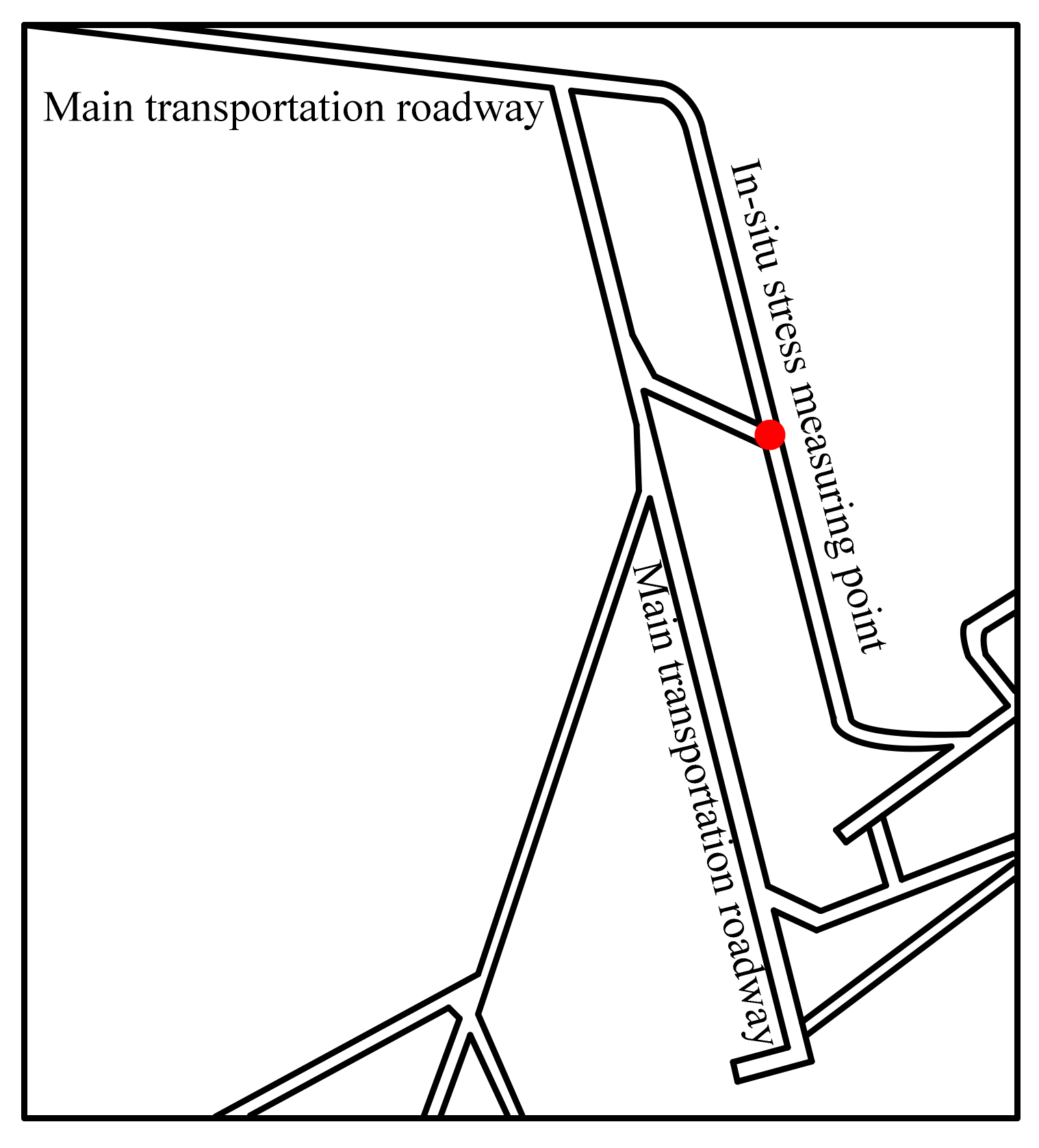
2.1. Mine Overview

The typical engineering background of this numerical model is the transportation roadway of the south 205 working face in Qing’shui Coal Mine, Liaoning, China (Figure 1). Qing’shui Coal Mine is located in the southeastern part of the Shenbei coalfield. The mining object is lignite. The designed mining depth is 50–900 m. The development mode is a district inclined shaft. The mining method is longwall mining on the strike. The production capacity of the mine has been approved as 900,000 tons/year, the buried depth along the transportation roadway is 552 to 587 m, and the inclination angle is 9–25 degrees [23].

2.2. Geomechanics Parameters of Roadway Surrounding Rock

According to the in-situ stress test, the surrounding rock strength test and surrounding rock structure observation in Qing’shui Coal Mine, the geomechanical parameters of the roadway surrounding rock in the south 205 working face of Qing’shui Coal Mine are as follows:
(1) In-situ stress test
Based on former research results [24], the stress relief method was used to measure the in-situ stress and the in-situ stress measuring point was located in the roadway crossing of −450 shaft station, as shown in Figure 2. The results of the in situ stress measurement are listed in Table 1.
In Table 1, H is the buried depth of the measuring point; σV, σH, σh are vertical stress, maximum and minimum horizontal principal stresses, respectively.
(2) Surrounding Rock Properties
The cross-section of transportation roadway is a straight wall and a semi-circular arch with a width of 5.4 m, an arch height of 2.7 m and a wall height of 1.2 m, as shown in Figure 3. The lithological column diagram of the roadway surrounding rock is shown in Figure 4. The physical and mechanical parameters of roadway surrounding rock are shown in Table 2.
(3) Surrounding rock structure
The microstructure scanning results of the electron microscopy experiment on the surrounding rock of transportation roadway in the south 205 working face are shown in Figure 5.
It can be seen from Figure 5 that micro-fractures with a width of about 5 to 20 microns and a large number of randomly distributed joints can be found in coal, mudstone and tuff. Due to the high development of micro-fractures and joints in roadway surrounding rock, the overall micro-structure of the surrounding rock was poor. Under the stress disturbance caused by roadway excavation, micro-fractures can easily extend and incorporate through the joint surface of rock mass. Fragmentation, dilatation and even instability failures then occurred in surrounding rock.

3. Deformation Failure Characteristics of Coal Roadway Stability in Gently Inclined Jointed Rock Mass

Through previous field investigation and monitoring, as shown in Figure 6, the deformation failure characteristics of transportation roadway were summarized as follows [23]:
(1)
Influenced by the gradual release of deviator stress to the air due to roadway excavation, the cross-section of roadway surrounding rock continuously shrank. The surrounding rock deformation tended to be stable for more than 70 days. The average deformation rates of roof, floor and side to side within 75 days were 7 mm/d, 9 mm/d and 8 mm/d, respectively.
(2)
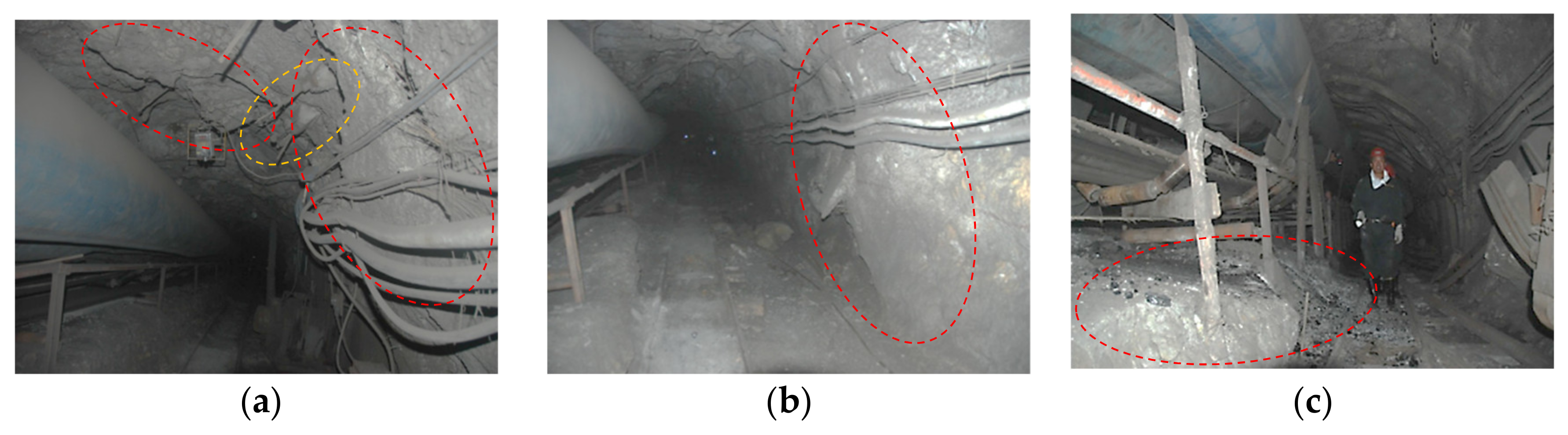
The deformation distribution was obviously asymmetric, as shown in Figure 6. The convergence of roof to floor of entry was 1.35–2.0 times larger than that of the rib to rib. In addition, the floor heave accounted for 57%–63% of the roof to floor convergence, which was dominant. The heave degree of the right side of the floor was significantly more serious than the left side. The middle and right sides of the roof suffered severe spalling and dilation failures and obvious convexity generated in the right rib.
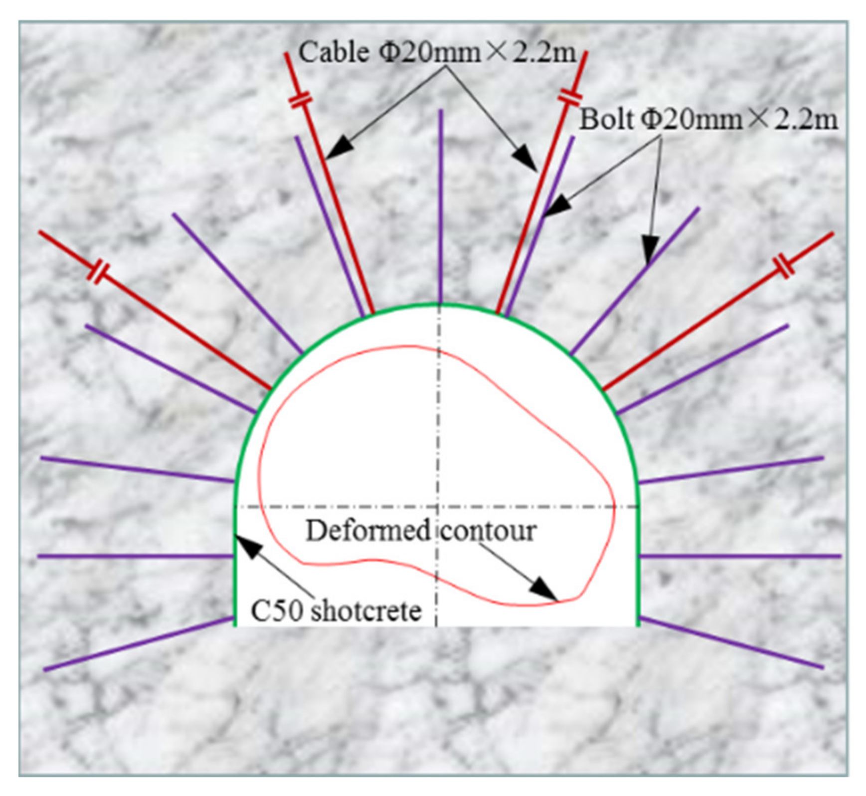
(3)
The support pattern of the transportation adopted the “Bolt-cable-concrete” active support structure, as shown in Figure 7. Thirteen Φ20 mm × 2.2 m rebar bolts were installed in the full cross-section with row spacing of 0.8 m and column spacing of 0.8 m. Four Φ15.24 mm × 7.3m strand bolts were installed in the roof cross-section with a row spacing of 1.6 m and column spacing of 1.2 m. The strength of shotcrete was C20 with a thickness of 100mm. As shown in Figure 6a, shotcrete spalling and cable broken failures frequently occurred in middle and ride side of roof and right rib.

4. Numerical Modeling of Coal Roadway Stability in Gently Inclined Jointed Rock Mass

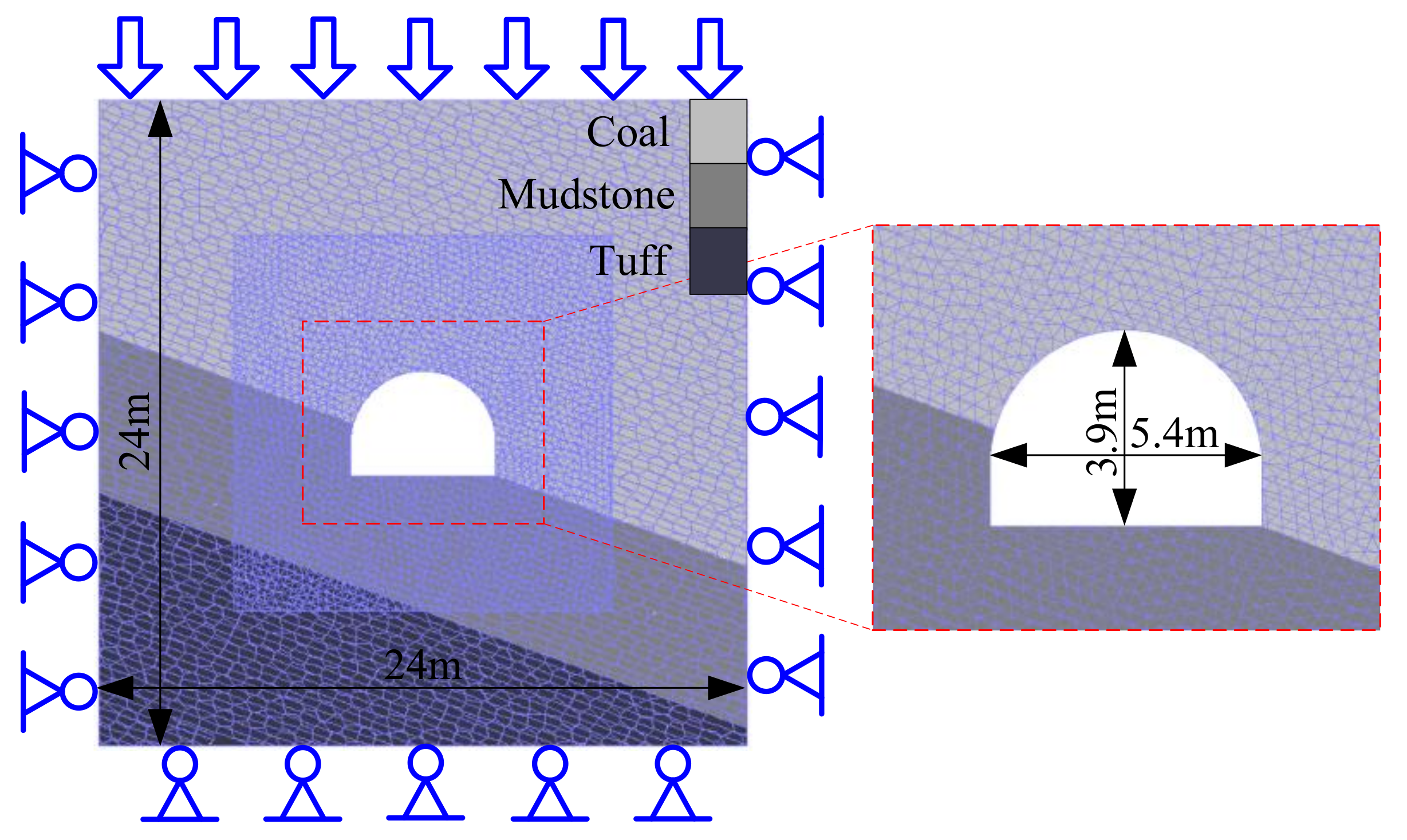
4.1. Establishment of Numerical Model

The algorithm attribute of UDEC is very suitable for simulating the large deformation movement of rock mass, the rotation of rock block and the separation of rock block along the joint surface. Therefore, it can accurately and intuitively reproduce the large deformation failure of surrounding rock caused by roof collapse, rib spalling and floor heave [27]. Therefore, the UDEC discrete element software was adopted to study the instability mechanism of coal roadway in gently inclined jointed rock mass due to excavation unloading [28]. The algorithm of discrete element software UDEC divided the computational domain into discrete blocks whose boundaries were connected by interlaced structural planes and the structural planes between these blocks are regarded as contact surfaces [29].
Considering that the fracture behavior of rock mass is mainly determined by the stress state of the contact surface, the elastic constitutive model is used for the constitutive model of the complete rock block, and the Coulomb slip model is used for the constitutive model of the contact surface [30].
In the normal direction of the contact surface:
Δ σ n = k n Δ μ n
In Equation (1), kn is the normal stiffness of the contact surface, and Δσn and Δun are the normal effective stress increment and the displacement increment of the contact surface, respectively.
When the effective stress in the vertical direction of the contact surface exceeds the ultimate tensile strength of the contact surface, Δσn = 0.
In the tangential direction of the contact surface, if
τ s c + σ n tan φ = τ max
In Equation (2), τs is the tangential stress of the contact surface, c is the cohesion of the contact surface, σn is the normal effective stress of the contact surface, φ is the internal friction angle of the contact surface, τmax is the shear strength of the contact surface.
Then
Δ τ s = k s Δ μ s e
In Equation (3), ks is the tangential stiffness of the contact surface, Δτs is the tangential stress increment of the contact surface, Δuse is the tangential displacement increment of the elastic stage.
Otherwise, if
τ s τ max
then
Δ τ s = sign Δ μ s τ max
In Equation (5), Δus is the tangential displacement increment of the whole stage.
The formation, propagation and incorporation of micro-cracks can be visually represented by the slip and opening of the contact surface. When the deviating stress on the contact surface exceeds its tensile or shear strength, the contact surface produces shear slip failure or tension opening failure [20]. Because the triangular discrete block can better simulate the slip, opening, expansion and incorporation of cracks [30], the surrounding rock in the study area around the roadway was divided into discrete random triangular blocks to simulate the rock blocks cut by random joints. To enhance the computational efficiency, rock masses in other regions were divided into discrete random polygon blocks to simulate rock blocks cut by random joints. In the whole numerical calculation model, the intersecting joints with a spacing of 0.3 m and a dip angle of 20 degrees were generated, and the distribution patterns of the larger bedding and joints in the actual gently inclined strata were simulated. The edge length of random triangular block should be small enough to reveal the law of fracture development in rock mass. In this simulation, the edge length of a random triangular block was 0.3 m. The edge length of a random polygon block was increased by 0.6 m in order to eliminate the problem of reducing the accuracy of model operation due to the sudden increase of block size.
Based on the geomechanical conditions of the transportation roadway, a discrete element numerical model of coal roadway in gently inclined jointed rock mass was established, as shown in Figure 8. The width and height of the model were both 24 × 24 m. The size of the model was large enough to eliminate the boundary effect. The excavation section size of coal roadway in gently inclined jointed rock mass was the same as the above-mentioned actual size. The model consists of 650,432 blocks, 1,822,142 contact surfaces and 1,200,467 triangular mesh elements. According to the initial in-situ stress measured by the stress relief method, the initial maximum horizontal stress of 17.652 MPa was applied on the left and right sides of the model, the initial minimum horizontal stress of 8.832 MPa was applied parallel to the direction of the roadway excavation, and the initial vertical stress of 14.508 MPa was applied on the top boundary of the model. Both sides and the bottom boundary of the model were fixed. A vertical stress of 14.508 MPa with a stress growth gradient of 0.023 MPa/m was applied on the top of the model to simulate the gravity of overlying strata.

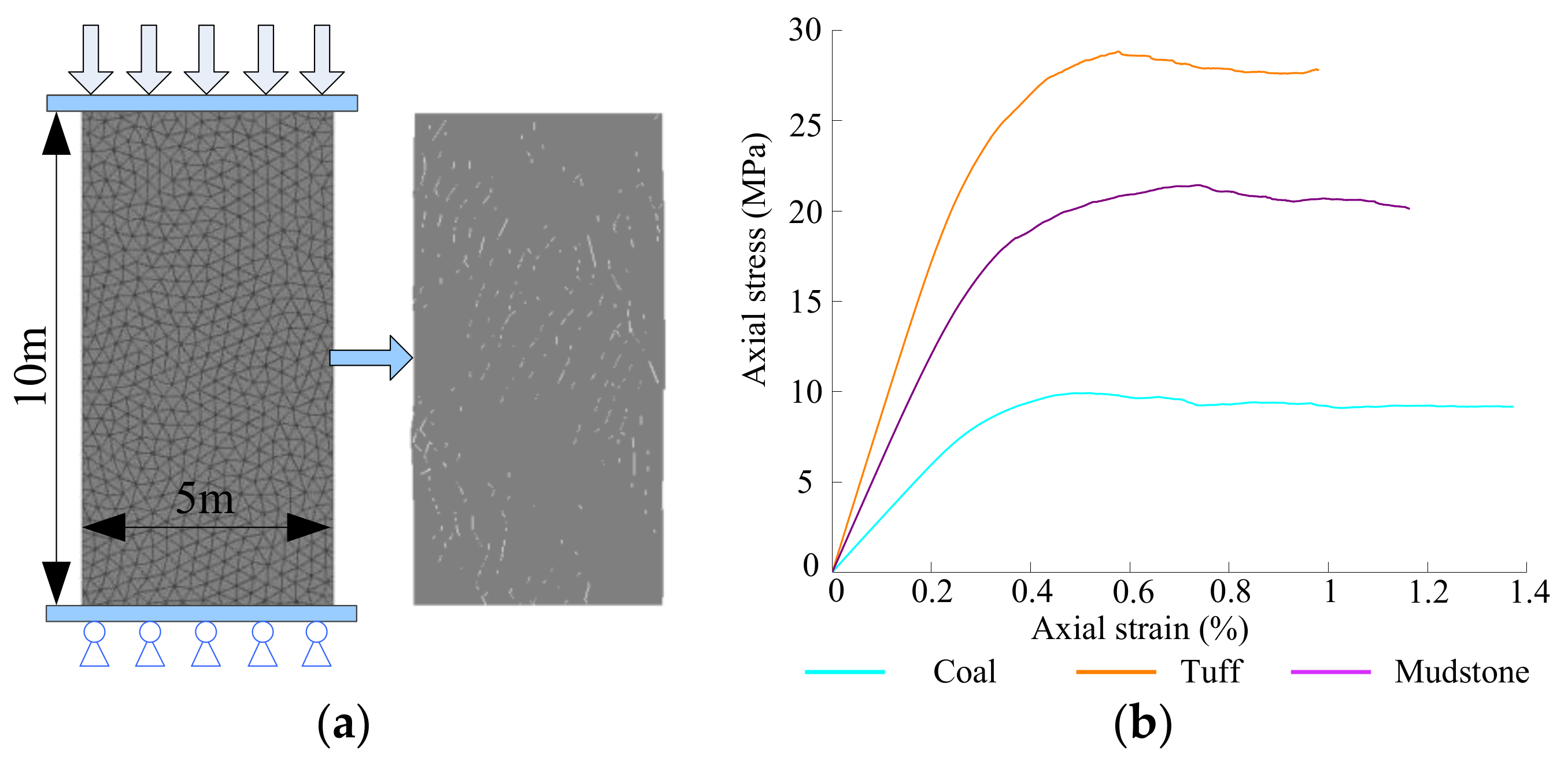
4.2. Calibration of Rock Mass Parameters

The density of rock blocks used in the numerical model was equal to the density of rock masses listed in Table 2. The bulk modulus K and shear modulus G were calculated by the elastic modulus and Poisson’s ratio of rock masses listed in Table 2 according to Equations (6) and (7), respectively. The tensile strength of the contact was calculated by one-twelfth of the compressive strength of rock masses [20]. The physical and mechanical parameters, such as normal stiffness kn, tangential stiffness ks, cohesion C and internal friction angle φ of the contact surface, were calibrated according to the elastic model and compressive strength of rock mass listed in Table 2. The calibration process was realized through a series of uniaxial compression tests on numerical specimens. The calibrated specimens have the same joint and mesh distribution as the rock stratum in the numerical model, the length and width of the specimens were 10 and 5 m, respectively, as shown in Figure 9a. The elastic modulus of rock mass was determined by the tangential and normal stiffness of the contact surface [31]. The range of the tangential and normal stiffness of the contact surface [32] were calculated by Equation (8).
K = E 3 1 - 2 μ
G = E 2 1 + μ
k n = n K + 4 3 G Δ Z min , 1 n 10
In the Equations (6)–(8), K and G are the rock bulk modulus and shear modulus, respectively, E and μ are the elastic modulus and Poisson’s ratio, respectively, and ΔZmin is the minimum mesh element length of the model. Tangential stiffness ks = 0.4kn.
The compressive strength of the rock mass was determined by the cohesion of the contact surface and the internal friction angle. Firstly, the initial values of the mechanical parameters of the contact surface that need to be calibrated were estimated according to the mechanical properties of the rock mass. Then, uniaxial compression experiments were iteratively conducted on numerical specimens and the initial values of the mechanical parameters of the contact surface which need to be calibrated were adjusted continuously according to the elastic model and the compressive strength of the rock mass obtained from the stress–strain curve until the elastic modulus and compressive strength of the rock mass obtained from the stress–strain curve were approximately equal to the elastic modulus and compressive strength of the rock mass listed in Table 2. In order to ensure that the specimen fully yielded and entered the post-peak failure state, the numerical uniaxial compression test ran 10,000 steps, and the loading rate was 0.1 m/s. The above-mentioned optimal stress–strain curves obtained from the numerical uniaxial compression tests are shown in Figure 9b. The physical and mechanical parameters of the rock blocks and contact surfaces for the numerical model calculation were calibrated and obtained as shown in Table 3. The values of the elastic modulus and compressive strength obtained by calibration are shown in Table 4. It can be seen that they were approximately equal to the values of the target elastic modulus and compressive strength. Therefore, the physical and mechanical parameters of rock blocks and contact surfaces listed in Table 3 can be adopted to calculate the unloading numerical model for roadway excavated in deep gently inclined jointed rock masses.

4.3. Numerical Simulation Scheme

After the boundary conditions of the numerical model and the actual in-situ stress level were applied, the initial in-situ stress field, which was consistent with the engineering geomechanics model, was formed by calculating the model to the equilibrium state. Then, according to the actual size of the transport entry, the region inside the entry cross-section was deleted to simulate roadway excavation. In order to simulate the stress unloading process caused by entry excavation more accurately, the stress data of the surrounding rock on the roadway surface were collected by means of the UDEC embedded FISH language program and were divided into 10 stages of gradual release. The stress release of each grade decreased by 10%, until the stress unloading on roadway surrounding rock surface was completed and the stress value decreased to 0. The model ran enough steps in each unloading stage until the unbalanced force coefficient was reduced to 1 × 10⁻⁵. In order to eliminate the effect of reinforcement on the evolution law of stress, fracture and displacement, the excavated roadway model was unsupported. In order to obtain the law of displacement evolution during excavation unloading process of the roadway surrounding rock, the displacement in the surrounding rock of roadway studied were monitored by monitoring points and lines. The layout of monitoring points and lines is shown in Figure 10. The monitoring points were used to monitor the surface displacement evolution process of critical points in the surrounding rock during excavation unloading process. The monitoring lines were used to monitor the ultimate displacement values at different depths of surrounding rock.

5. Instability Failure Characteristics of Coal Roadway in Slowly Inclined Jointed Rock Mass Due to Excavation Unloading

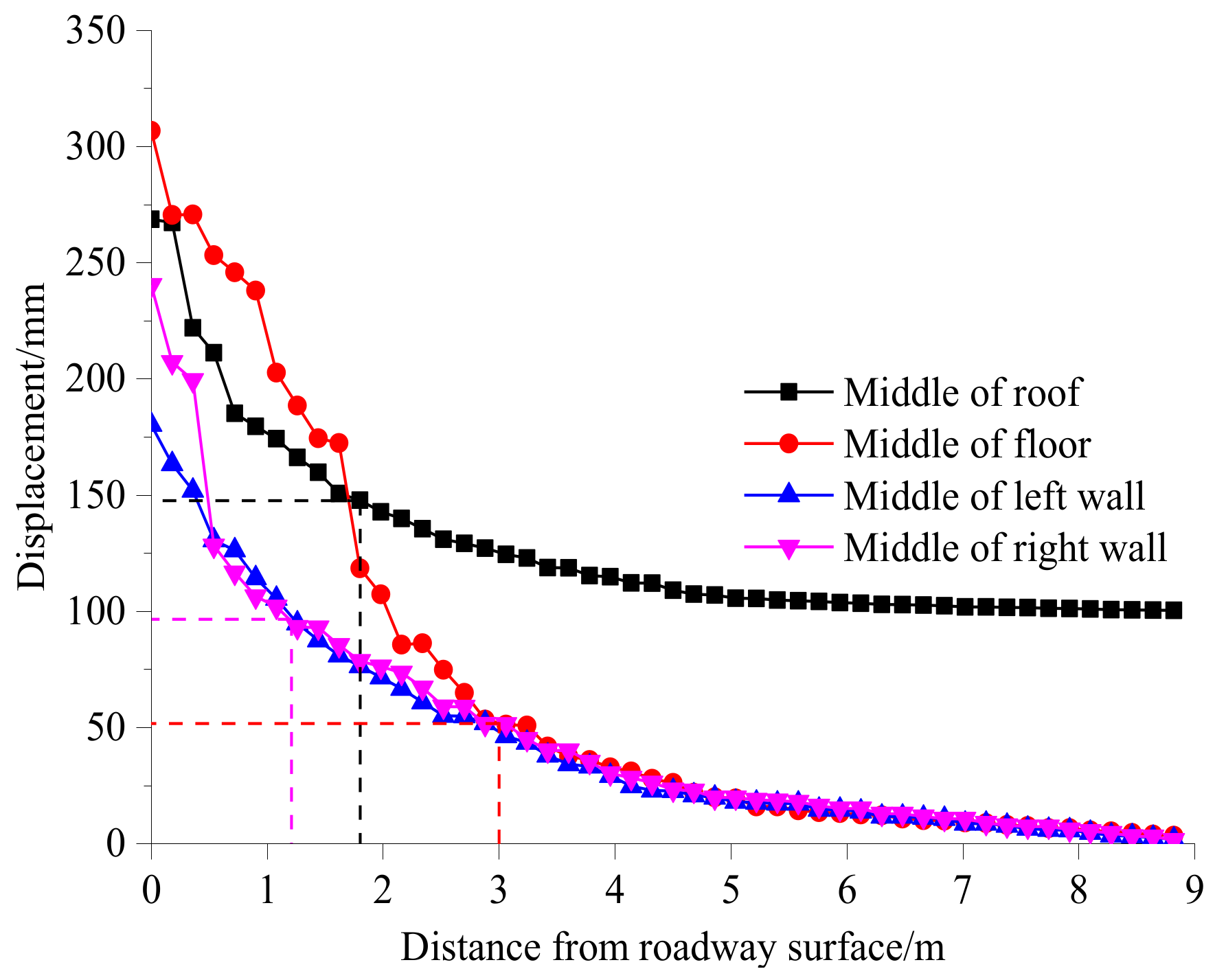
5.1. Deformation Characteristics

As shown in Figure 11, the final displacement vector map of the roadway surrounding rock shows that the roadway surrounding rock moved toward the free face and presented obvious asymmetric deformation characteristics. The deformation degree of the left side in the floor and the right side in the roof were most severe due to the deflection deformation. The maximum deformation of the roadway floor appeared on the left side and decreased, in turn, to the middle and right sides; the overall deformation degree of the floor was large. The maximum deformation of the roadway roof appeared on the right side. The degree and range of deformation decreased gradually to the middle, right of the roof and right rib. The range of deformation in the right rib was larger than that in the left rib. The measured and calculated convergence values in the critical location of the roadway are shown in Table 5. It can be seen from Table 5 that the field and simulated convergence values in the right arch shoulder was similar, which indicated in the most severe deformation location, the support materials completely failed soon after installation and deviator stress released totally. In the middle of roof and right rib, compared with simulated convergence values, the reduction rate of field measured convergence values were 15%–20%, which indicated that the support materials failed when the deviator stress release to a certain degree. In the left arch shoulder and left rib, compared with simulated convergence values, the reduction rate of field measured convergence values were approximately 40%, which indicated the support materials did not occur failures and interaction with the deviator stress in most degree. The field measured convergence values in floor were larger than the simulated convergence values, which indicated the deviator stress transferred from roof and rib to floor due to the lack of support materials in floor.
The surface displacement curve of the key points on the roadway surface is shown in Figure 12. With the gradual release of deviatoric stress, the surface displacement presented a step-by-step upward trend and the deformation rate was increasing in each stress release stage. When the stress release stage 8 was entered, the deformation rate of the left side and middle side of roadway floor began to increase significantly. When the last stress release stage was entered, the deformation of the whole surrounding rock increased obviously and there was no steady sign, indicating that the surrounding rock of the roadway entered into a large deformation instability stage. The maximum displacements of the surrounding rock on the left side, middle and right side of the roadway floor were 486, 307, 143 mm, respectively, which indicates that the deformation degree of the floor surrounding rock decreased from left to right. The maximum deformations of the surrounding rock at the right arch shoulder, middle, left arch shoulder of the roof were 311, 274 and 212 mm, respectively, which indicates that the deformation degree of the roof surrounding rock decreased from right to left. The maximum convexities of the surrounding rock in the middle part of the left rib and right rib were 179 and 240 mm, respectively; the deformation degree of the right rib was greater than that of the left rib. The deformation degree of the left side of the floor and the right side of the roof increased most significantly.
Monitored lines were arranged in the middle of the roof, floor and two walls of the roadway to monitor the final displacement of the surrounding rock at different depths in the range of 0–9 m. The distance between the measuring points on the line was 0.18 m and 50 measuring points were arranged. The monitoring results are shown in Figure 13. It can be seen that the degree of displacement fluctuation in the floor was the most intense. The fluctuation depth in the floor was 3 m from the floor surface. The degree of displacement fluctuation in the left rib was greater than that of the right rib. The fluctuation depth in both ribs was 1.2 m from the rib surface. The depth of the displacement fluctuation in the roof was 1.8 m from the roof surface. The degree and range of displacement fluctuation reflected the extent of fragmentation and dilatation in the roadway surrounding rock. It can be seen that the degree of fragmentation and dilatation in the roof and floor were the most severe, followed by the right wall, and the left wall was the least severe.

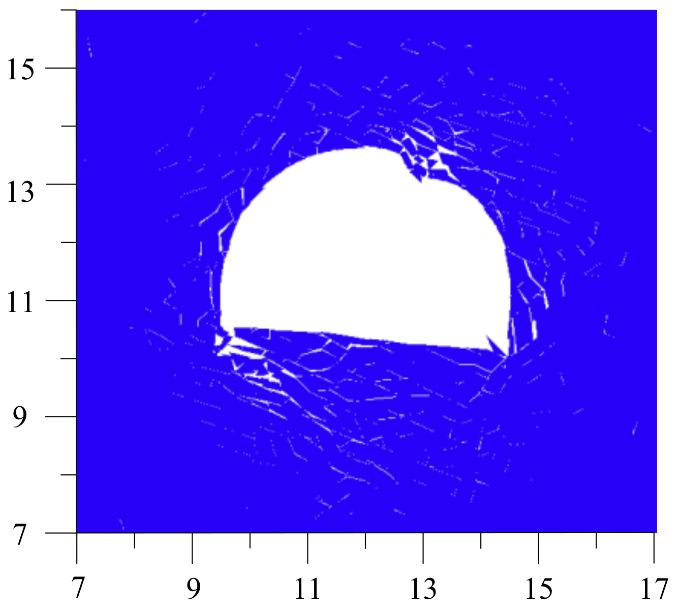
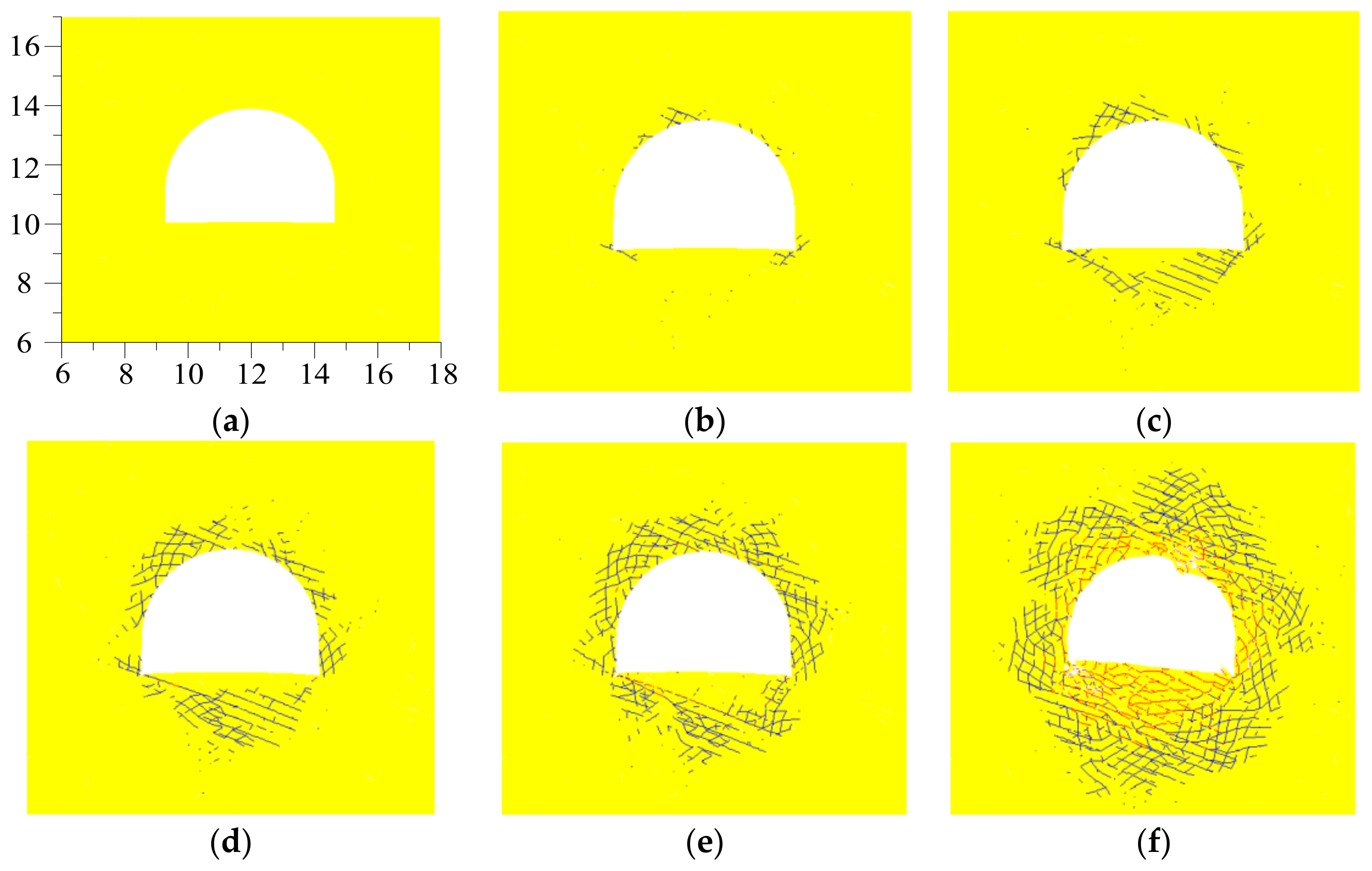
5.2. Macroscopic Fracture Propagation Characters

The final distribution of macro fractures in the roadway surrounding rock is shown in Figure 14. Roof caving, floor heave and rib spalling generated in the right arch shoulder of the roof, the left side of the floor and the right rib, respectively. A large number of macro fractures developed in the roadway surrounding rock, which caused the serious fragmentation and dilatation deformation. The larger the opening degree, the longer the coalescent length and the more serious the fragmentation and dilation deformation degree in the roadway surrounding rock. The degree of fragmentation and dilation deformation in the left side of the floor and the right side of the roof were the most serious, followed by the right rib and the least serious in the left rib. Therefore, the failure characteristics of the roadway surrounding rock were serious asymmetric fragmentation and dilatation deformation, which is in good agreement with the field investigation.

5.3. Microscopic Fracture Propagation Characters

The process of micro crack development and propagation in the surrounding rock of roadway is shown in Figure 15. The blue line represents shear crack and the red line represented tension crack. The shear crack first generated in the corner of floor and the middle of roof and extended to other parts of shallow surrounding rock. Then, the shear cracks propagated to the deep surrounding rock; a number of long coalescent shear cracks formed in the floor and the right side of the roof. At unloading stage 9, the tension cracks generated in the left side of the floor and the right side of the roof. At unloading stage 10, the tension cracks developed rapidly and extended to other parts of the shallow surrounding rock. A number of long coalescent tension cracks formed in the left side of the floor and the right side of the roof. The tension crack development range of the floor was the largest, followed by the roof and the right rib, while, for the left rib, it was the smallest. It can be seen that the distribution pattern of the tension cracks is consistent with that of the macro fractures, which indicates that the development and propagation of the tension crack caused the generation, propagation and incorporation of macro fractures in the surrounding rock. The asymmetric long coalescent tension cracks caused the serious fragmentation and dilation deformation in the left side of the floor and the right arch shoulder of the roof.

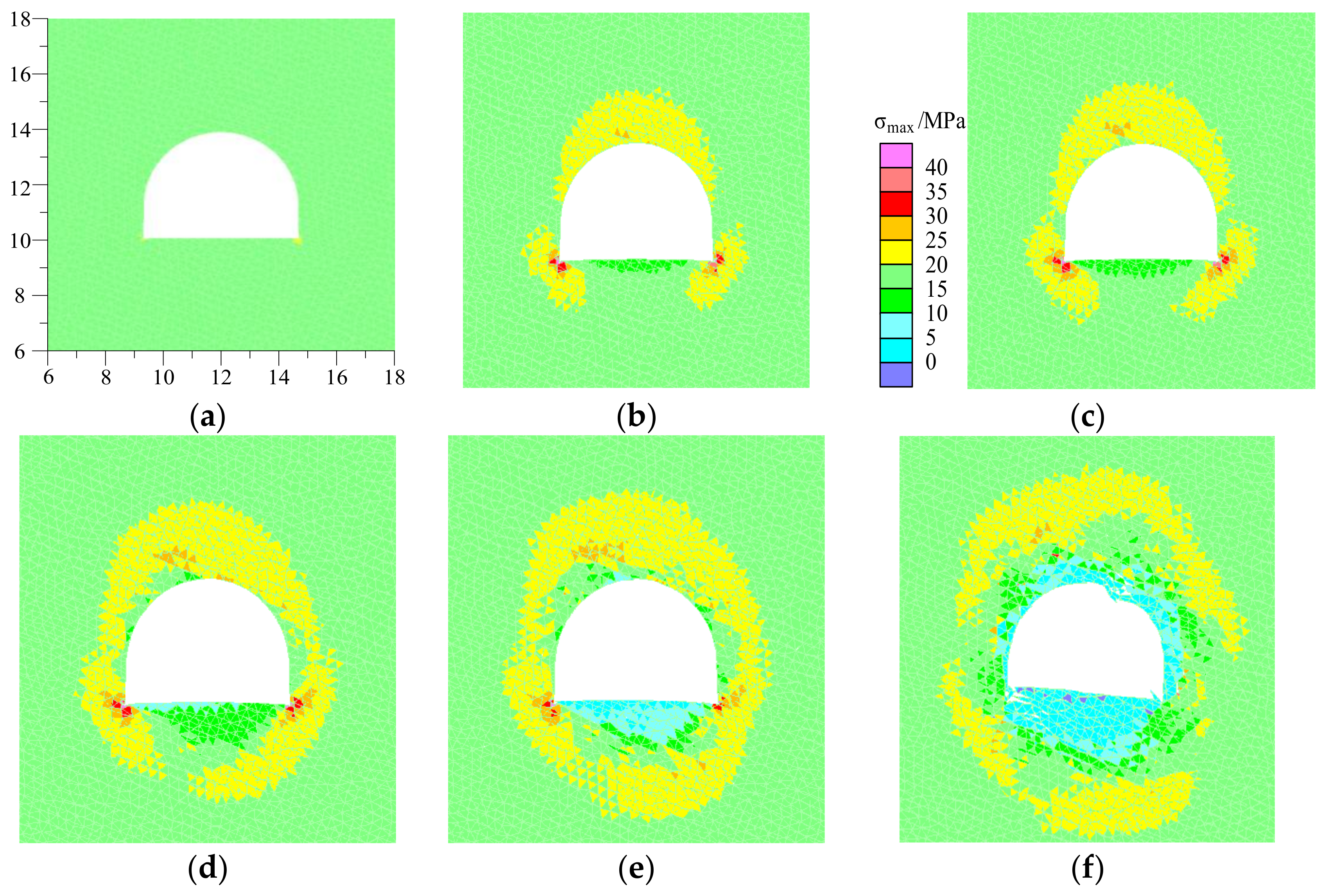
5.4. Stress Evolution Characters

The evolution process of the maximum principal stress is shown in Figure 16. Stress concentration refers to the difference value of principal stress exceed the in-situ stress. During the unloading stage, stress concentration first occurred at the corner of the floor and the middle of the roof. With the increase in the unloading degree, the stress concentration scope in the corner of the floor and the middle of the roof increased continuously, which finally incorporated and propagated into the deep surrounding rock. When the stress concentration degree exceeded the bearing strength of surrounding rock, the stress release zone began to appear in the shallow surrounding rock and extended continuously to the deep surrounding rock. The stress release degree in the stress release zone increased continuously until the model ran to the equilibrium state. The stress release degree and range of floor was the largest, followed by the middle, the right side of roof and right rib, while, for the left side of roof and left rib, it was the least. The stress release degree of the left side of the floor was larger than that of the right side of the floor. It can be seen that the concentration of the maximum principal stress in the surrounding rock caused the generation, propagation and incorporation of the shear cracks in the entry surrounding rock and the subsequent release of the maximum principal stress in the surrounding rock caused the generation, propagation and incorporation of the tension cracks.
Because the stress release degree on left side of the floor was the most serious, five maximum principal stress monitoring points were arranged on the left side of the roadway floor to reveal the law of stress evolution during excavation unloading process of the roadway surrounding rock, as shown in Figure 10. The first measuring point was laid on the floor surface 0.9 m away from the left rib. The following measuring points were laid out in parallel to the first measuring point at intervals of 0.5, 1, 1.5 and 2 m, respectively. The monitoring results of the maximum principal stress evolution process of the key points are shown in Figure 17. The monitoring points at 0, 1.5, 3 and 5 m maintained the stress release state during the whole unloading process. The stress release pattern shows a step-down trend. From unloading stage 8, the stress release rate began to increase significantly. The final stress release rates of the stress monitoring point at 0, 1.5, 3 and 5 m were 100%, 93.7%, 58.6% and 40.5%, respectively. The maximum principal stress at the 0-m measuring point released completely. The stress release rate of other measuring points decreased with the increase in depth. It can be seen that the stress release rate and the degree of the four measuring points show a decreasing trend with the increase in depth from the floor surface. The maximum principal stress measuring point at 0.5 m increased gradually from unloading stages 1 to 7, which indicates the process of stress concentration. In unloading stages 8 to 10, the maximum principal stress decreased rapidly, which indicates the process of stress release. The final stress release rate of this measuring point was 60.9%, which indicates that partial deviatoric stress was exhausted by the bearing strength of the surrounding rock.
The evolution process of tension stress in the roadway surrounding rock is shown in Figure 18. The tension stress began to generate in the stress release zone when the maximum principal stress released completely. The acting degree of tension stress in the floor was the most severe, followed by the middle and right side of the roof. The tension stress caused the generation, propagation and incorporation of tension cracks in the entry surrounding rock [33], especially the long coalescent tension cracks.

6. Discussion

On the basis of roadway instability failure characters of simulated results and field investigation, the asymmetric large deformation failure mechanism of coal roadway stability in gently inclined jointed rock mass due to excavation unloading has been revealed, which can be summarized as follows:
(1)
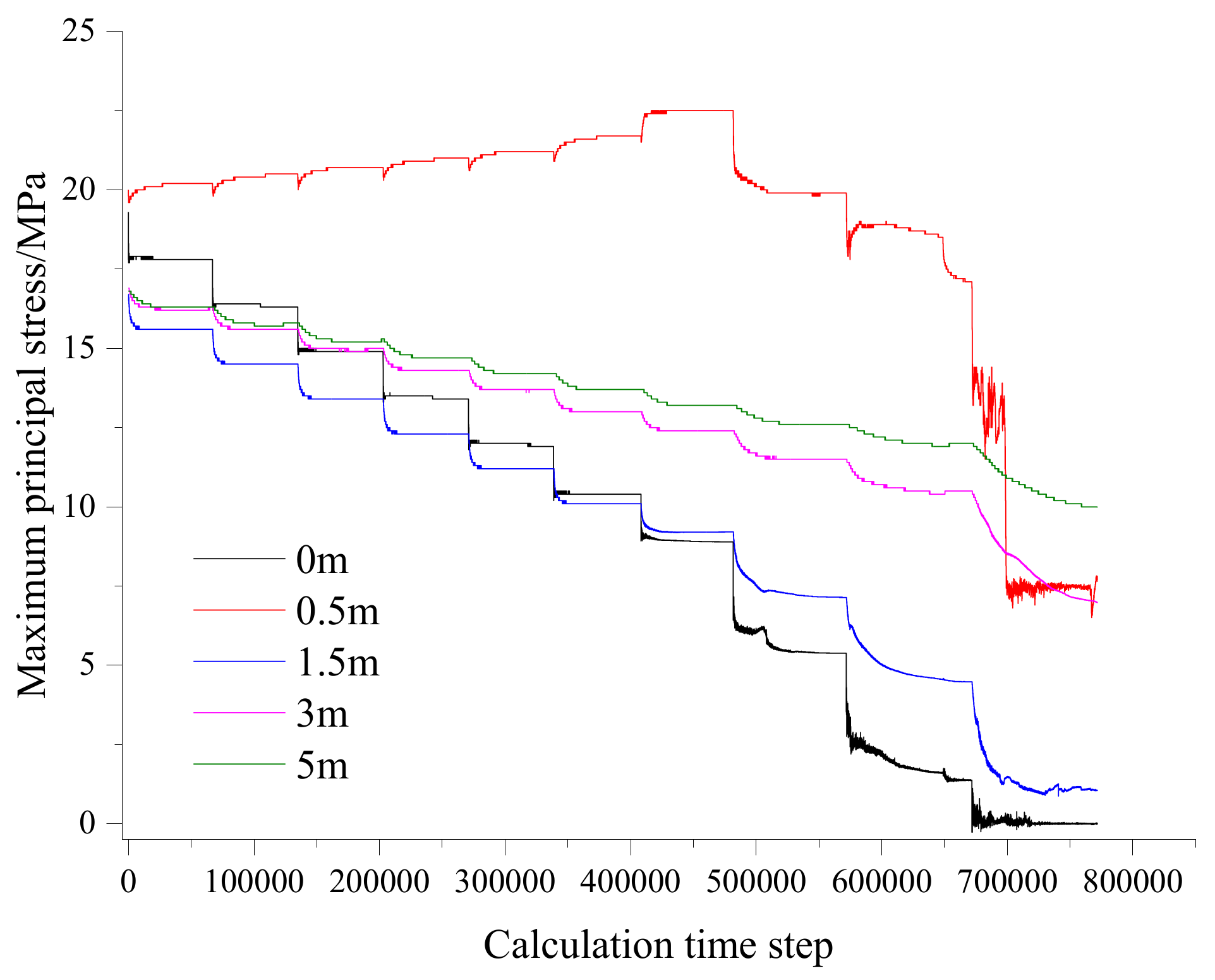
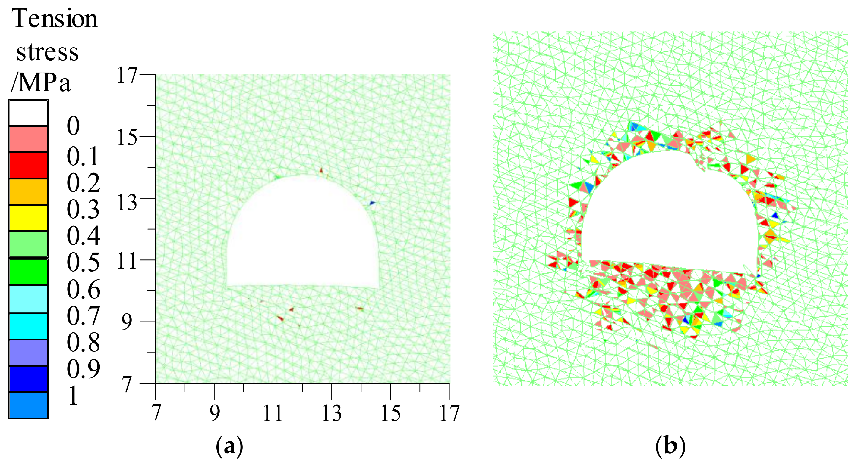
The gradual release of deviator stress due to excavation unloading caused the generation, incorporated and propagated of stress concentration zone in roadway surrounding rock. When the stress concentration degree exceeded the bearing strength of the surrounding rock, the stress release zone began to appear in surrounding rock. The stress release degree in the stress release zone increased continuously until the model ran to the equilibrium state. The tension stress began to generate in the stress release zone when the maximum principal stress released completely.
(2)
The concentration of the maximum principal stress caused the generation, propagation and incorporation of shear cracks. A number of long coalescent shear cracks formed in the floor and the right side of the roof. The tension stress caused the generation, propagation and incorporation of tension cracks in the entry surrounding rock. A number of long coalescent tension cracks formed in the left side of the floor and the right side of the roof.
(3)
The development and propagation of the tension crack caused the generation, propagation and incorporation of macro fractures in surrounding rock, which caused serious fragmentation and dilatation deformation. The asymmetric long coalescent tension cracks caused serious fragmentation and dilation deformation in the left side of the floor and the right side of the roof. Roof caving, floor heave and rib spalling generated in the right side of the roof, the left side of the floor and the right rib, respectively, the simulated failure characteristics is in good agreement with the field investigation.
(4)
The bearing strength of the support structure was too low to resist the concentrated stress. The enhancing of the bearing strength of support structure could reduce the stress concentration degree and range, then inhibit the generation and develop of shear cracks, especially the long coalescent shear cracks. The confining pressure applied by the pre-stress on the active support structure was insufficient. The enhancing of confining pressure can significantly increase the residual strength of surrounding rock [34] and greatly reduce the stress release degree and the range, then restrain the generation of tension stress and tension crack. The elongation of active support structure was too small to inhibit the fragmentation and dilatation deformation in surrounding rock. The enhancing of elongation of active support structure can inhibit the slip, open and incorporation of macro fractures in the surrounding rock.

7. Conclusions

The large deformation failure degree of coal roadway stability in jointed surrounding rock due to excavation unloading is becoming more and more serious. In view of this, field engineering geomechanical model tests and discrete element simulations were conducted in this paper to study the gradual instability failure characteristics and mechanisms of coal roadway in gently inclined jointed rock mass due to excavation unloading. Based on the above research results, the following conclusions can be drawn:
(1)
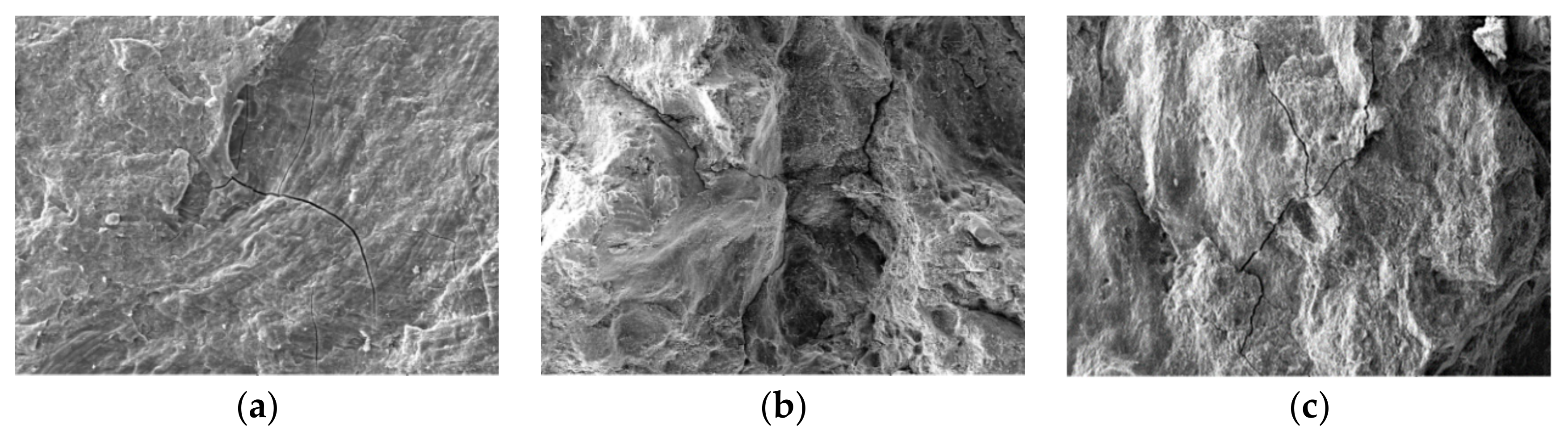
The surrounding rock structure scanning results reveal that micro-fractures and a large number of randomly distributed joints can be found in roadway surrounding rock. Under the stress disturbance caused by roadway excavation, micro-fractures extend and incorporate through the joint surface of the rock mass. Fragmentation, dilatation and even instability failures then occurred in the surrounding rock.
(2)
The field investigation and monitoring of deformation failure characteristics in surrounding rock indicated that the cross-section of roadway surrounding rock continuously shrank. The deformation distribution was obviously asymmetric. The convergence of the roof to floor of entry was obviously larger than that of the rib to rib. Moreover, the floor heave was dominant in the roof to floor convergence. The heave degree of the left side of the floor was significantly more serious than the right side. The middle and right sides of the roof suffered severe spalling and dilation failures, and obvious convexity generated in the right rib. Support structure failures frequently occurred in middle and ride side of roof and right rib.
(3)
The asymmetric large deformation failure mechanism of coal roadway stability in gently inclined jointed rock mass due to excavation unloading has been revealed by the discrete element method combining with field engineering tests. With the increase in the excavation unloading degree, the stress concentration zone generated, incorporated and propagated to the deep surrounding rock. The concentration of the maximum principal stress caused the generation, propagation and incorporation of shear cracks. A number of long coalescent shear cracks formed in the floor and the right side of the roof. When the stress concentration degree exceeded the bearing strength of the surrounding rock, the stress release zone began to appear in shallow surrounding rock and extended continuously to the deep surrounding rock. The stress release degree in the stress release zone increased continuously until the model ran to the equilibrium state. The tension stress began to generate in the stress release zone when the maximum principal stress released completely. The tension stress caused the generation, propagation and incorporation of tension cracks in the roadway surrounding rock. A number of long coalescent tension cracks formed in the left side of the floor and the right side of the roof. The development and propagation of the tension crack caused the generation, propagation and incorporation of macro fractures in surrounding rock, which caused serious asymmetric fragmentation and dilatation deformation. The bearing strength of the support structure was too low to resist the concentrated stress. The confining pressure applied to the support structure was insufficient to restrain the crack propagation. The elongation of the support structure was too small to inhibit the fragmentation and dilatation deformation in surrounding rock. In this paper, the influence of excavation unloading on coal roadway stability in jointed surrounding rock was studied, mainly focusing on stress, crack evolution and deformation failure processes. Further field engineering tests and numerical simulations are needed to study the control effects of high bearing strength, high pre-stress and large elongation reinforcement measures on the serious asymmetric fragmentation and dilatation deformation in the jointed rock mass of a coal roadway due to excavation unloading.

Author Contributions

X.Y. and E.W. conceived the theme; E.W. designed and performed the numerical simulation tests; G.Z. performed the laboratory experiments and field tests; G.C. and W.G. provided theoretical and technical guidance; E.W. and G.C. processed and analyzed the data. E.W. wrote the paper. All authors have read and agreed to the published version of the manuscript.

Funding

This research was supported by the National Natural Science Foundation of China (Grant No.41672347) and Innovation Fund Project of Inner Mongolia University of Science and Technology (Grant No.2019QDL-B34).

Conflicts of Interest

The authors declare no conflict of interest.

References

  1. Milici, R.C.; Flores, R.M.; Stricker, G.D. Coal resources, reserves and peak coal production in the United States. Int. J. Coal Geol. 2013, 113, 109–115. [Google Scholar] [CrossRef]
  2. Yang, X.J.; Wang, E.Y.; Ma, X.G.; Zhang, G.F.; Huang, R.F.; Lou, H.P. A case study on optimization and control techniques for entry stability in Non-Pillar Longwall Mining. Energies 2019, 12, 391. [Google Scholar] [CrossRef] [Green Version]
  3. Lu, J. Research on Support Technique of Deep Soft Rock Mining Roadway in Qingyun Coal Mine. Master’s Thesis, Taiyuan University of Technology, Taiyuan, China, 2019. [Google Scholar]
  4. Hu, Z.Q.; Xiao, W.; Wang, P.J.; Zhao, Y.L. Concurrent mining and reclamation for underground coal mining. J. China Coal Soc. 2013, 38, 301–307. [Google Scholar] [CrossRef]
  5. Kang, H.P. Sixty years development and prospects of rock bolting technology for underground coal mine roadways in China. J. China Min. Technol. 2016, 45, 1071–1081. [Google Scholar] [CrossRef]
  6. Kang, H.P. Support technologies for deep and complex roadways in underground coal mines: A review. Int. J. Coal Sci. Technol. 2014, 1, 261–277. [Google Scholar] [CrossRef] [Green Version]
  7. Kang, H.P.; Wu, Z.G.; Gao, F.Q.; Ju, W.J. Effect of geological structures on in-situ stress distribution in underground coal mines. Chin. J. Rock Mech. Eng. 2012, 31, 2674–2680. [Google Scholar] [CrossRef]
  8. Jing, H.W.; Li, Y.H.; Xu, G.A.; Chen, K.F. Analysis of displacement of broken surrounding rock of deep roadway. J. China Min. Technol. 2006, 35, 565–570. [Google Scholar] [CrossRef]
  9. Yang, X.X.; Kulatilake, P.H.S.W.; Jing, H.W.; Yang, S.Q. Numerical simulation of a jointed rock block mechanical behavior adjacent to an underground excavation and comparison with physical model test results. Tunn. Undergr. Space Technol. 2015, 50, 129–142. [Google Scholar] [CrossRef]
  10. Xie, H.P.; Gao, F.; Ju, Y. Research and Development of Rock mechanics in Deep Ground Engineering. Chin. J. Rock Mech. Eng. 2015, 34, 2161–2178. [Google Scholar] [CrossRef]
  11. Yang, S.Q.; Chen, M.; Jing, H.W.; Chen, K.F.; Meng, B. A case study on large deformation failure mechanism of deep soft rock roadway in Xin’An coal mine, China. Eng Geol. 2017, 217, 89–101. [Google Scholar] [CrossRef]
  12. Feng, F.; Chen, S.J.; Li, D.Y.; Hu, S.T.; Huang, W.P.; Li, B. Analysis of fractures of a hard rock specimen via unloading of central hole with different sectional shapes. Energy Sci. Eng. 2019, 7, 2265–2286. [Google Scholar] [CrossRef] [Green Version]
  13. Gao, F.Q.; Stead, D.; Coggan, J. Evaluation of coal longwall caving characteristics using an innovative UDEC Trigon approach. Comput. Geotech. 2014, 55, 448–460. [Google Scholar] [CrossRef] [Green Version]
  14. Maleki, H.; Stewart, C.; Stone, R.; Abshire, J. Practical Application of Numerical Modeling for the Study of Sudden Floor Heave Failure Mechanisms. In Proceedings of the international workshop on numerical modeling for underground mine excavation design, Pittsburgh, PA, USA, 28 June 2009; pp. 89–100. [Google Scholar]
  15. Souley, M.; Françoise, H.; Thoraval, A. The effect of joint constitutive laws on the modelling of an underground excavation and comparison with in situ measurements. Int. J. Rock Mech. Min. 1997, 34, 97–115. [Google Scholar] [CrossRef]
  16. Feng, F.; Li, X.B.; Rostami, J.; Peng, D.X.; Li, D.Y.; Du, K. Numerical investigation of hard rock strength and fracturing under polyaxial compression based on Mogi-Coulomb failure criterion. Int. J. Geomech. 2019, 19, 04019005. [Google Scholar] [CrossRef]
  17. Alejano, L.R.; Taboada, J.; García-Bastante, F.; Rodriguez, P. Multi-approach back analysis of a roof bed collapse in a mining room excavated in stratified rock. Int. J. Rock Mech. Min. Sci. 2008, 45, 899–913. [Google Scholar] [CrossRef]
  18. Zang, C.W.; Chen, M.; Zhang, G.C.; Wang, K.; Gu, D.D. Research on the failure process and stability control technology in a deep roadway: Numerical simulation and field test. Energy Sci. Eng. 2020, 00, 1–14. [Google Scholar] [CrossRef] [Green Version]
  19. Li, X.H.; Ju, M.H.; Yao, Q.L.; Zhou, J.; Chong, Z.H. Numerical investigation of the effect of the location of critical rock block fracture on crack evolution in a gob-side filling wall. Rock Mech. Rock Eng. 2016, 49, 1041–1058. [Google Scholar] [CrossRef]
  20. Kang, H.P.; Lin, J.; Fan, M.J. Investigation on support pattern of a coal mine roadway within soft rocks—A case study. Int. J. Coal. Geol. 2015, 140, 31–40. [Google Scholar] [CrossRef]
  21. Wang, P.; Jiang, L.S.; Zheng, P.Q.; Qin, G.P.; Zhang, C. Inducing mode analysis of rock burst in fault-affected zone with a hard-thick stratum occurrence, Environ. Earth Sci. 2019, 78, 467. [Google Scholar] [CrossRef]
  22. Le, T.D.; Oh, J.; Hebblewhite, B.; Zhang, C.G.; Mitra, R. A discontinuum modelling approach for investigation of Longwall Top Coal Caving mechanisms. Int. J. Rock Mech. Min. 2018, 106, 84–95. [Google Scholar] [CrossRef]
  23. Zhang, G.F.; Yu, S.B.; Li, G.F.; Huo, J.Y. Research on complementary supporting system of constant resistance with load release for three-soft mining roadway in extremely thick coal seam. Chin. J. Rock Mech. Eng. 2011, 30, 1619–1626. [Google Scholar] [CrossRef]
  24. Yang, X.J.; Pang, J.W.; Lou, H.P.; Fan, L.P. Characteristics of in situ stress field at Qingshui coal mine. Int. J. Min. Sci. Technol. 2015, 25, 497–501. [Google Scholar] [CrossRef]
  25. Yin, J.Y. Failure Mechanism and Supporting Measures of Deep Coal Roadway in Shenbei Mining Area. Ph.D. Thesis, China University of Mining and Technology, Beijing, China, 2012. [Google Scholar]
  26. Wang, E.Y. Modeling of Failure Mechanism and Control Techniques for Entry Stability in Slowly Inclined Jointed Rock Mass Due to Excavation Unloading Effect. Ph.D. Thesis, China University of Mining and Technology, Beijing, China, 2019. [Google Scholar]
  27. Gao, F.Q.; Stead, D.; Kang, H.P.; Wu, Y.Z. Discrete element modelling of deformation and damage of a roadway driven along an unstable goaf—A case study. Int. J. Coal. Geol. 2014, 127, 100–110. [Google Scholar] [CrossRef]
  28. Yang, X.J.; Wang, E.Y.; Wang, Y.J.; Gao, Y.B.; Wang, P. A Study of the Large Deformation Mechanism and Control Techniques for Deep Soft Rock Roadways. Sustainability 2018, 10, 1100. [Google Scholar] [CrossRef] [Green Version]
  29. Itasca Consulting Group, Inc. UDEC User Manual; Itasca Consulting Group, Inc.: Minneapolis, MN, USA, 2008. [Google Scholar]
  30. Ma, W.Q.; Wang, T.X. Compression failure characteristics and crack propagation of brittle rock under various confining pressures. Chin. J. Rock Mech. Eng. 2018, 37, 898–908. [Google Scholar] [CrossRef]
  31. Gao, F.Q.; Stead, D. The application of a modified Voronoi logic to brittle fracture modelling at the laboratory and field scale. Int. J. Rock Mech. Min. Sci. 2014, 68, 1–14. [Google Scholar] [CrossRef]
  32. Cho, N.; Martin, C.D.; Sego, D.C. A clumped particle model for rock. Int. J. Rock Mech. Min. 2007, 44, 997–1010. [Google Scholar] [CrossRef]
  33. Diederichs, M.; Kaiser, P.; Eberhardt, E. Damage initiation and propagation in hard rock during tunnelling and the influence of near-face stress rotation. Int. J. Rock Mech. Min. Sci. 2004, 41, 785–812. [Google Scholar] [CrossRef]
  34. Goel, R.K.; Swarup, A.; Sheorey, P.R. Bolt length requirement in underground openings. Int. J. Rock Mech. Min. Sci. 2007, 44, 802–811. [Google Scholar] [CrossRef]
Figure 1. Location of the Qing’shui coal mine, Liaoning, China.
Energies 13 02515 g001
Figure 2. Arrangement of ground stress measuring points in the no.2 mining area.
Energies 13 02515 g002
Figure 3. Schematic diagram of roadway cross section size.
Energies 13 02515 g003
Figure 4. Stratum column and geological description at the study site [25].
Energies 13 02515 g004
Figure 5. SEM results of the roadway surrounding rock [25]: (a) coal (150 times larger); (b) mudstone (100 times larger); (c) tuff (100 times larger).
Energies 13 02515 g005
Figure 6. Asymmetric failure mode in the coal roadway [23]: (a) asymmetrical roof shrinkage deformation and support failure; (b) asymmetrical side extrusion deformation; (c) asymmetrical floor heave deformation.
Energies 13 02515 g006
Figure 7. Support pattern and final failure characteristics of roadway surrounding rock.
Energies 13 02515 g007
Figure 8. Numerical model for the coal roadway.
Energies 13 02515 g008
Figure 9. Results of simulated uniaxial compression test for the rock mass: (a) numerical uniaxial compression test; (b) optimal stress–strain curve.
Energies 13 02515 g009
Figure 10. The location of monitoring points and lines in roadway surrounding rock.
Energies 13 02515 g010
Figure 11. Displacement field evolution characters in the roadway surrounding rock during the excavation unloading process.
Energies 13 02515 g011
Figure 12. Displacement evolution characters in critical points during the excavation unloading process.
Energies 13 02515 g012
Figure 13. Simulated displacement distribution characters in the different depth of the roadway surrounding rock.
Energies 13 02515 g013
Figure 14. Simulated final deformation failure pattern of the roadway due to excavation unloading.
Energies 13 02515 g014
Figure 15. Development of shear and tension cracks in the roadway surrounding rock during the excavation unloading process: (a) unloading stage 1; (b) unloading stage 6; (c) unloading stage 7; (d) unloading stage 8; (e) unloading stage 9; (f) unloading stage 10.
Energies 13 02515 g015
Figure 16. Maximum principal stress evolution characters in the roadway surrounding rock during the excavation unloading process: (a) unloading stage 1; (b) unloading stage 6; (c) unloading stage 7; (d) unloading stage 8; (e) unloading stage; (f) unloading stage 10.
Energies 13 02515 g016
Figure 17. Maximum principal stress evolution characters in the critical points during the excavation unloading process.
Energies 13 02515 g017
Figure 18. Tension stress evolution characters in the roadway surrounding rock during the excavation unloading process: (a) unloading stage 9; (b) unloading stage 10.
Energies 13 02515 g018
Table 1. Ground stress value of no.2 mining area.
Measuring Point LocationH/mσV/MPaσH/MPaσh/MPa
−450 shaft station52014.50817.6528.832
Table 2. Physical and mechanical parameters of roadway surrounding rock mass [26].
LithologyDensity/(kg/m3)Compressive Strength/MPaTensile Strength/MPaElastic Modulus/GPaPoisson RatioCohesion/MPaInternal Friction/°
Coal16.09.820.973.040.2101.0923
Mudstone25.320.621.926.390.1492.2427
Tuff25.629.212.779.060.1353.2632
Table 3. Calibrated rock mass mechanical parameters of simulated rock mass.
LithologyBlock ParametersContact Parameters
Density
/(kg·m−3)
Bulk Modulus
/GPa
Shear
Modulus
/GP
kn
/(GPa·m−1)
ks
/(GPa·m−1)
Cj
/MPa
φj
/(°)
σtj
/MPa
Coal16.01.751.26338.14135.261.71300.97
Mudstone25.33.032.78849.46339.783.04341.92
Tuff25.64.143.991230.58492.233.35382.77
Table 4. Calibrated Young’s modulus and the compressive strength value in the UDEC model.
LithologyElastic Modulus
/GPa
Error (%)Compressive Strength
/MPa
Error (%)
Target ValueSimulation ValueTarget ValueSimulation Value
Coal3.043.050.339.829.921.02
Mudstone6.396.252.1920.6221.443.98
Tuff9.068.793.0029.2128.831.30
Table 5. Measured and calculated convergence values in critical location of roadway.
Convergence/mmMiddle of RoofLeft Arch ShoulderRight Arch ShoulderMiddle of FloorLeft Side of FloorRight Side of FloorMiddle Of Left RibMiddle Of Right Rib
Calculated values 274212311307486143179240
Measured values232134308322508153108194

