Abstract
The control methods of asynchronous motors have changed during past decades. In the past, asynchronous motors were connected to grid directly. Later, thyristors as switching element-based frequency converters for asynchronous motors have appeared. Today, asynchronous motors are controlled with variable speed drives that are frequency converters consisting of IGBT power modules as switching elements that form the output voltage for asynchronous motors. Because of IGBT’s high switching speed of around few kilohertz, higher order harmonics appear in the output voltage. Their influence was not analyzed in the past as the methodology of asynchronous motor winding resistance measurement was under development. In this article, a new methodology of motor resistance measurement for mass production is introduced. The resistance—compared to higher order harmonics values between the windings of benchmark and tested motors—gives an ability to faster and more accurately determine a motor’s characteristics and losses induced by higher order harmonics that appear when a motor is powered by a variable speed drive. Motor winding’s inductance dependency on the current of magnetic biasing and the higher frequency of voltage is analyzed in this article. In addition, the simulation model of resistance to higher order harmonics of motor measurement is introduced and analyzed in this article.
1. Introduction
Most of the today’s drive components consist of asynchronous motors, paired with a frequency converter. Because industrial frequency converters are mostly of the impulse type, their switching frequency is usually higher than one kilohertz. As a result, a full spectrum of higher harmonics—lowering the motor’s energy efficiency—is formed. So, it is crucial to maximize the energy efficiency of motors powered by frequency converters as the price of electricity increases. For this purpose, it is essential to analyze the processes developing in an asynchronous motor powered by a frequency converter. The question of what electromagnetic processes are developing inside an asynchronous motor when it is powered by a quite high frequency voltage has not been analyzed enough. Because formerly there were no high frequencies in the voltage fed to the motor, this question was not simply asked. This question became relevant when frequency converters with IGBT transistors as switches were introduced. At first, these converters were thyristor-type, and their voltage harmonics frequency range were relatively low. In publications from that time [1,2], mostly 5th and 7th harmonics’ influence on motor performance were analyzed, respectively. In research [3], spatial as well as time harmonics influence on asynchronous motor powered by frequency converter were analyzed. Time harmonics were analyzed for a converter which was operating without a sine pulse wide modulation (PWM), as well as without higher switching frequencies with a four-level power supply, where mostly lower-order harmonics were dominating. Consequently, the results acquired in previously mentioned research have little adaptability for the case of modern frequency converters. An assumption was made in the research: that both stators’ and rotors’ resistances are static as frequency is changing, and reactive resistances are higher than the reactive resistance for the first harmonic times the order of harmonic. In other words, the parameters for the first harmonic in equivalent scheme of induction motor—where inductive impedances are replaced with corresponding inductances—is the same as for the higher-order harmonics. Furthermore, the same assumptions are made in other publications, for example [4], where computer modeling is reviewed. These assumptions do not represent real processes occurring in induction motors. As the frequency of voltage increases, motor resistance also increases, for two main reasons: First—resistance increased in the rotor of the motor because the skin effect in the rotors short-circuited the winding bars. The second reason was increased contributed resistance, because of losses with increasing eddy currents in the magnetic core of the stator, which was inductively connected with the stator winding current.
Today’s frequency converters use IGBT’s as commutators. This allows switching frequencies up to 12 kHz. Therefore harmonics—close to the switching frequency of the output voltage of converters—are expressed.
There is published research in which the frequency is dependent on resistance, while motor is powered with a frequency converter, since law-modulated voltage impulses in the output, is considered [5,6]. In this research, it is proposed that all motor resistance alterations take place in short-circuited cage bars of the rotor, because of the skin effect from current flow. The influence of losses increasing in magnetic wire was not considered. It was assumed that the ratio of motors active and reactive resistance was constant as frequency changes. It was stated that it was determined experimentally, although the experiment itself was not described. The experimental verification of assumptions made was a balance of power: the calculated sum of active power of higher order harmonics was equal to difference of losses when powered from frequency converter and losses when powered from sinusoidal voltage.
There were no publications found where research or methodology for research of motors resistance to time harmonics were substantiated. The aim of this research is to substantiate a methodology for this experimental research and to acquire results suitable for practical use. Most researchers use simulations, and unfortunately in these, inductances are constant and do not correspond to the frequencies of the harmonics [7,8]. If the increase of frequency is minor at the same time lower harmonics dominate, the change of inductance is also minor and can be ignored. For the frequency close to switching frequency of modern frequency converter, losses in magnetic wire of motors stator are quite significant. They are so great that for the main magnetic flux frequency—in for example, a transformer—electrical steel was not used. This transformer would use a lot of power and would draw much current from the grid, even at idle. In other words, as frequency increases, so does the current drawn, even at idle. However, an increase of current would indicate a decrease of resistances, especially in inductive resistance. An obvious conclusion can be made that inductive resistance is not a constant value, and it decreases as the frequency increases. This especially applies to frequencies that are further from the limits of frequencies that are used for electrical steel cores. In research [9], an output voltage modulation law optimization problem for inverter was analyzed, to decrease the losses, created by higher voltage harmonics of inverter. Optimization was done by simulation and both, inductances and resistances in equivalent scheme are constant values. In publication [10], harmonic level in different inverter schemes—assuming all other values were constant— was analyzed. In article [11], experimental research results are presented in which the harmonic spectrum was measured. The measurement results were not accurate, however, because they were achieved by using a grid power analyzer, which measures only up to the 17th harmonic. This is in range where higher harmonics are marginally expressed. For these types of measurements, only converter power analyzers are valid, because they are designed to measure spectral compositions of voltages and currents of converters. In [12], optimization of pulse wide modulation principle was investigated by simulating the system in Simulink application. In the model equivalent scheme of motor with constant inductances was used. The problems of minimization of harmonic levels by simulating was also researched in publication [13]. Morevover, in [14], a case of resistance determination was analyzed—also by assuming that parameters of equivalent scheme were independent from frequency.
There are not many motor resistance measurement regulations. Standards, for example IEEE–112, provide three main tests for motor resistance measurements. These are: stators resistance measurements by using direct current; idle (not loaded motor) tests with nominal frequency voltage and short-circuit (with suspended rotor) experiment, with nominal frequency voltage. The problem is if it is possible to determine resistances of a motor—not only for the main harmonic, but also to higher order harmonics—by using the experiments mentioned above. It is obvious that an idle test is not always possible to implement. As can be seen from Figure 1, the highest amplitude harmonic frequency is around five kilohertz. In the case of two-pole motor, the rotation speed would be around 300,000 min−1. It is technically impossible to achieve this speed. On the other hand, if this rotational speed were even possible, no significance would the measurement have, if it were accomplished at the speed that a motor would never work. Hence, would it be better to execute the experiment when motor is rotating at a speed close to rotating speed of the first harmonic. This test would have a purpose, and some researchers are doing it [14]. Slip for this harmonic, if the rotor is rotating at the speed which only consists of 1% of the rotational speed of the harmonic, practically equals to 1. This means, that the measurement result would be the same if rotor is rotating, or if it would be suspended. Further, in research [15], authors are periodically commutating the motor at a considerably high frequency, both to the grid for support of rotation and to the harmonic frequency supply, for measurement. How much the result is influenced by induced voltage by transitional processes is hard to discern. Because of this, the results of the experiment are questionable. Hence, it is obvious, that the measurement must be carried out with rotor of the motor suspended. Problem is to determinate if the experiment should be carried out by using three phase or one phase power supply. It is obvious, that one phase power supply is sufficient for the experiment, because in case of symmetrical three phase system and with symmetrical load, power from one phase to the other is not transmitted. Hence, for both cases, the three phases, as well as for the one phase power supplies of harmonic frequency, the measurement results would be the same. Another problem is the selection of power supply. Because, size of motors magnetic flux as well as density of magnetic flux, in both stator and rotor magnetic wires of the motor depends from the power supply voltage. Magnetic permeability factor of ferromagnetic magnetic wire depends on magnetic field strength. In addition, inductance of the motor winding, depends on magnetic flux, which is determined by voltage of power supply. Although this can only be applied for the case of main harmonic. Higher order harmonics create only additional components of magnetic flux and they do not define the saturation of the core.
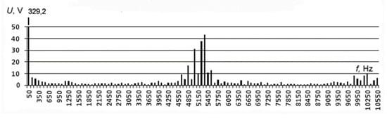
Figure 1.
Output voltage frequency spectrum of modern frequency converter.
A conclusion can be made, that by measuring the resistances of motor winding, voltage of power supply is not significant and can be marginal, although over-magnetization of the core, corresponding to created over-magnetization of the motor of main harmonic while in operation mode is important. Basically, a methodology of measurement proposed, correspond to direct current machines winding inductance measurement methodology, when inductance is used to measure with alternating current, but over-magnetizing is done with direct current, which is provided in IEEE–113 standard and described in detail in [16]. A capacitor and inductance is used to separate the circuits for both direct and alternating currents, this allows alternating current to flow through the capacitor, but direct current is blocked, and inductance allows direct current to flow, but it is resistive to alternating current. A simple one phase inductance measurement scheme, where the electric motors other two windings are magnetized, is given in Figure 2. Although this scheme has a major drawback—windings of phases W1.1–W2.1 and V2.1–V1.1—not only the magnetized phases U1.1–U2.1 in the direction of direct current flow in motors stators and rotors magnetic wires, but also in the direct current circuit, due to the electromotive force induced in the additional alternating current component created by the transformer bond, which loaded the measured circuit and caused measurement errors. To eliminate this error, it was later decided to measure the winding resistances in both motors at the same time, and to divide the result by factor of two. The windings of motors were connected in series, in the opposite direction as shown in Figure 3. The first pair of terminals of measuring device were connected to beginning of the first motors phase winding U1.1–U2.1, and to the phase ending a second motor’s phase winding ending U2.2 was connected. To the second pair of measurement device terminals, the second motor’s phase winding U2.1 beginning was connected. To the magnetization circuit second motors W1.2–W2.2 and V1.2–V2.2 phase windings were connected in series, using the same methodology as for the first motors winding. Because motors U1.1–U2.1 and U2.2–U1.2 phases are connected in the opposite direction, the electromotive force created in the magnetization circuit will be will be in the opposite directions and will compensate each other, because of transformer bond. This is because electrical circuit for both motors is mutual and magnetic circuits are different.
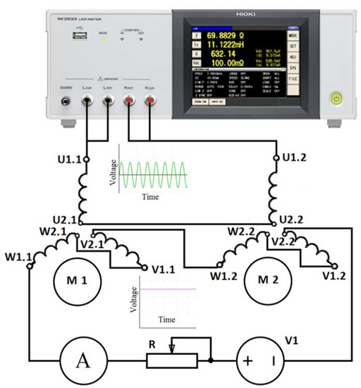
Figure 2.
Scheme of winding connection, compensating influence of measurement winding to motors magnetic.
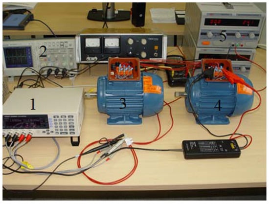
Figure 3.
General view of the experiment.
For motor designing stages several assumptions could be done, first the three phase motor is symmetrical, second only the fundamental harmonics is considered, while the higher harmonics of the special field distribution and of the Magneto Motive Force (MMF) in the airgap are disregarded, third the spatially distributed stator and rotor windings are replaced by a concentrated coil, forth effects of anisotropy, magnetic saturation, iron losses and eddy currents are neglected fifth coil resistance and reactance are taken to be constant, sixth in many cases, especially when considering steady state, the current and voltages are taken to be sinusoidal. As a result, only influence of the first harmonic 50 Hz is evaluated during asynchronous motor designing stage, but an influence of higher order harmonics for asynchronous motor is not evaluated. Furthermore, the influence of higher order harmonics is present when motor is supplied from variable speed drive. The main goal of the article is to investigate and reveal the influence of higher order harmonics for asynchronous motor in dynamic mode.
2. Materials and Methods
Considering, what was presented above, it was decided to measure winding resistances of the motor by using the Hioki LCR measurement device IM3523 (Hioki, Japan), with integrated alternating voltage generator up to 5 V, which can be adjusted in 50 Hz to 200 kHz frequency range. The base accuracy of the resistance measurement is 0.08%. To eliminate the possible effects of magnetization current on measurement results, it was decided to magnetize the system by using direct current. One phase of suspended motor was measured, while the other two phases were connected in a way that direction of their created of magnetic flux would correspond to direction of magnetic flux of the measured winding. Each magnetization windings direction of created flux composed a 60° angle with the created flux of measured winding, therefore a magnetic flux of each of the windings was created that corresponded to 0.5 of the flux size plane in the axis direction of the measured winding. Both projections were of the same direction and were summed, and projections that were perpendicular were of the different direction and their sum is equal to zero. Consequently, direction of magnetization flux, as previously mentioned, correspond to created magnetic flux of measured winding with the size of the flux the same as the amount of current flow in the measured winding. By using this scheme, magnetization current is flowing not in the measured circuit and will not have the effect on measurement itself. For the magnetization circuit not to have any effect on measurement circuit through transformer bond, two identical motors were selected for the experiment. As it is known that because of advanced technologies asynchronous motors, produced by WEG, dispersion of parameters from motor to motor is marginal, two WEG manufactured W22 series two pole motors with high efficiency class of IE2 and 0.75 kW nominal power were selected. The magnetization windings in both motors were connected identically and measurement–in different direction. Therefore, magnetization voltages were induced in both motors’ magnetization windings, while the currents that were flowing in the measurement windings had opposite directions and sum of the voltages in direct current magnetization circuit for both identical motors was equal to zero. Practically, a sum voltage of almost equal to zero is achieved because of unavoidable dispersion of motor parameters. Because both stators and rotors magnetic wires were grooved the resistance of winding is somewhat dependent from position of rotor and alternates as rotor is rotated with respect to stator.
At first, rotors position for one of the motors was selected such as preliminary resistances of windings would correspond to average value, then the rotors position of the second motor was selected by the minimum of the induced voltage in the measurement winding (yellow curve in Figure 4), it was done by connecting magnetization winding to industrial frequency voltage (blue curve in Figure 4).
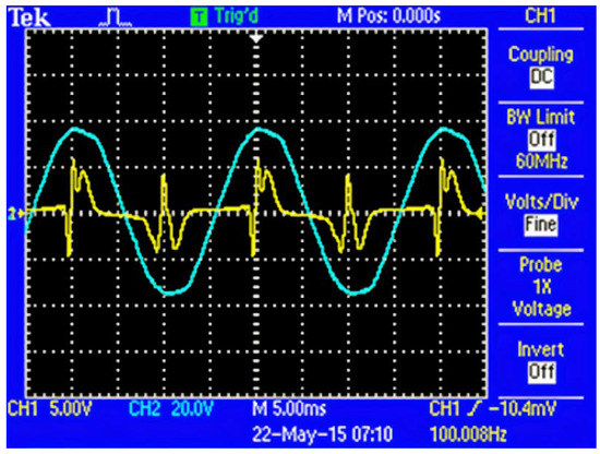
Figure 4.
Rotors position unification in respect to stator at starting position.
After selecting the positions, rotors were fixed and stayed the same in correspondence to stators for the entirety of the experiment. General view of the experiment with selected rotor positions are given in Figure 3. In Figure 3 the components of the experiment are presented: 1 Hioki LCR IM3523 meter, manufactured in Japan, 2 Tektroix TDS 2004B oscilloscope, manufactured in Oregon, USA, 3 and 4 are investigated WEG W22 0.75 kW motors, manufactured in Brazil and 5 DC power supply manufactured in China. The influence of position equalization of motors rotors to residual electromotive force is given in Figure 4 and Figure 5.
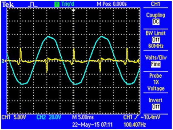
Figure 5.
Rotor position unification in respect to stator with minimal induced voltage.
Non-sinusoidal voltages in measurement winding (yellow curve) are obtained, because while compensating main voltage harmonics, higher harmonics are exposed.
3. Results
For better clarity on experimental results and the course of the experiments the result section is divided into two subsections: simulation model of motor resistance measurement and experimental results during motors rotors adjustment.
3.1. Model of Resistance to Higher Order Harmonics of Motor Measurement
Inevitably, a transformer bond between windings, decreasing the accuracy of measurement, is formed, while measuring electric motors resistance to higher order harmonics using sine wave signal, generated by Hioki LCR IM3523 or other typical LCR measurement device. A model was designed to test the effects of measurement signal to other windings of asynchronous motor. This model is given in Figure 6.
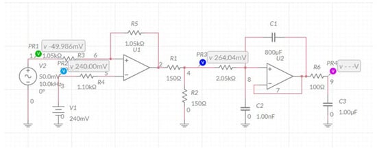
Figure 6.
A model of measured windings of asynchronous motor influence on other windings.
The input PR1 of operational amplifier U1 corresponds to measurement circuits U1.1–U2.1 sine voltage signal given in Figure 7. The input PR2 corresponds to direct voltage supply V1 voltage, at preset magnetization current. Resistances R3, R5 are at the amplification link and correspond to the primary windings transformation coefficient to the secondary winding and magnetic resistance in measured motors air gap. Influence of measurement signals of primary windings to secondary W1.1–V2.1 winding (voltage at point PR3), which in turn are fed from DC power supply, time charts are given in Figure 8.
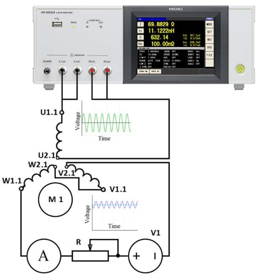
Figure 7.
Connection scheme of motors windings.
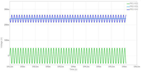
Figure 8.
Measurement circuits U1.1–U2.1 influence on secondary windings W1.1–V2.1-time charts.
Amplifier U2 corresponds to the second motor’s parameters of the model. The physical significance of the second motor’s connection to the measurement scheme as shown in Figure 6, is influence of measurement circuit to secondary windings of measured motor compensation (voltage at point PR4). In other words, second motor is utilized as a filter. Time charts for the model represented in Figure 3 are given in Figure 9.
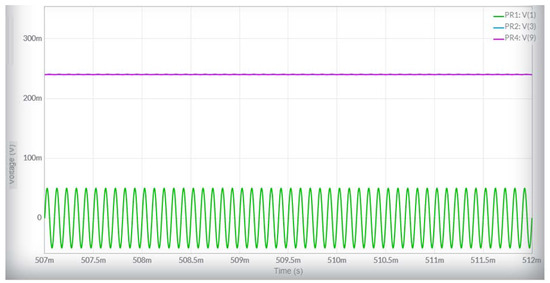
Figure 9.
Measurement circuits U1.1–U1.2, influence on secondary windings W1.1–V2.2-time charts, corresponding to diagram in Figure 3, model.
The scale for model and real system is 1:10.
3.2. Selection of Magnetization Current and Rotor Position Adjustment During the Measurement
Value of correct magnitude of magnetization current must be determined. It can be approximately considered that the amount of magnetic flux in asynchronous motor practically stays constant as the load alternates, because more than 90% of connected voltage are counterbalanced by electromotive force of the motor. At idle conditions currents of rotor are marginal and practically all the magnetic flux is generated by stators currents. Rotors position unification at starting position is represented in Figure 4. Where blue curve represents motors input voltage and yellow curve is inducted voltage each signal scale is 100 mV/V.
Rotors position in respect to stator with minimal induced voltage is represented in Figure 5. Where blue curve represents motors input voltage and yellow curve is inducted voltage each signal scale is 100 mV/V.
To comprise all the range of magnetization, the magnetization current’s highest value must not be lower than I_0*√2 A, because current amplitude at idle conditions is √2 times higher than effective value. Measured idle current of tested motors were 0.98 A, so the measurements were executed with 12 magnetization current values, ranging from 0 to 1.6 A. It is obvious, that for different magnetization current values, the resistance of windings values will also differ. The main issue is to select the correct magnetization current, when motors losses created by higher order harmonics are calculated. Because powers must be calculated, average squared or in other words effective values should be used. Consequently, main harmonics magnetization current’s period must be divided into equal time intervals and to find squared averages of corresponding resistance values, squared root of which would give the wanted value. For the first approach, the measured resistance values of the magnetization current—equal to idle current value—can be applied.
In Figure 10, impedance of winding and phase angle between impedance and resistances dependency from magnetization current at 50 Hz measurement frequency is given. As magnetization current is increased from zero to around 0.2 A, impedance also increases, this corresponds to dependence of magnetic permeability factor from magnetic field strength H in the rising part, as the magnetization current increases further it decreases, which corresponds to the decrease of same dependency as factor of magnetic permeability of electrical steel curve.
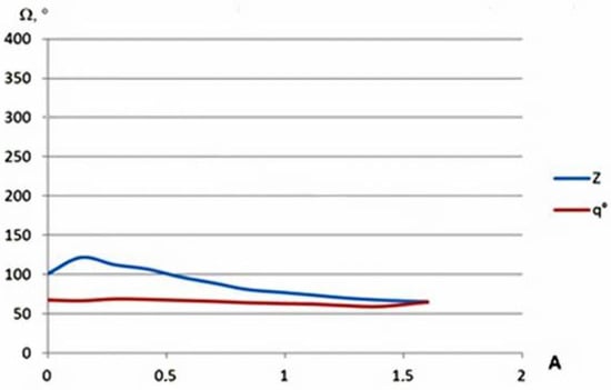
Figure 10.
Impedance of the winding (blue curve) and phase angle (red curve) at 50 Hz.
These characteristics of the winding, like impedance of winding and phase angle between impedance and resistances of winding, unequivocally characterizes unitary voltages for given frequency, which is connected to winding, creating relative power, or in other words power for voltage of 1 V. This power is equal to current, voltage and cosφ multiplication.
where:
- φ–phase angles between impedance and resistance of the winding.
- Z–impedance of the winding.
Power for any voltage connected can be discovered by multiplying the squared value of voltage with relative power.
This power is power of losses in the suspended motor because resistances were measured with suspended rotor. In Figure 11, the same dependencies are given with measurement frequency of 400 Hz.
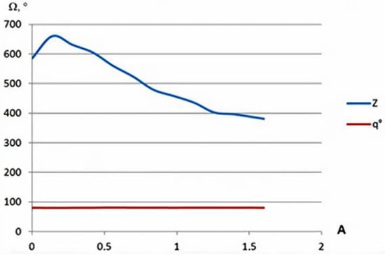
Figure 11.
Impendence of winding (blue curve) and phase angle (red curve) 400 Hz.
It is obvious, that comparative power of windings voltage and magnetization influence decrease as frequency increases. The impedance of windings dependence to current at 400 Hz can be written in polynomial Equation:
Z = 575.19 + 766.53 × I– 2936.59 × I 2 + 3855.92 × I 3– 2465.04 × I 4 + 729.41 × I 5– 70.65 × I 6
A more detailed review of the results is planned in separate article.
4. Conclusions
To summarize the work accomplished, these conclusions can be made:
- Motor winding’s impedance to higher order harmonics is an important parameter for evaluating additional losses in asynchronous motors powered from frequency converters. Therefore the methodology of these losses’ assessment must be incorporated into corresponding normative documents.
- This article offers a methodology for measuring a motor’s windings impedance, which could be applied with standard measurement equipment by specialists with intermediate technical knowledge.
- The measured impedance of windings at 400 Hz is equal to 65% of the winding impedance measured at 50 Hz, if motor inductance is calculated at 50 Hz. As frequency increases, the inductance of windings decreases. This assumption confirms relevance of the article.
- Motor winding’s impedance to higher order harmonics measurements must be applied to all power range and construction-type asynchronous machines; the results of these measurements must be empirical dependencies that could be applied in asynchronous machine designs stage for influence of higher order harmonics evaluation. The empirical dependence example is represented in Equation (2).
- The impedance of winding and phase angle curve in Figure 10 and Figure 11 corresponds with general features to curve, which represents factor of magnetic permeability of electrical steel. This relationship between curves is present because the inductive resistance of coils with magnetic core is proportional to the magnetic permeability factor. Magnetic permeability varies because of losses in the core when higher order harmonics are present, but the character of variations is similar.
- Relative power of losses of motor windings voltage is dependent not only on the magnetization current, but also on the frequency of the voltage.
- As the frequency of the voltage increases, the relative power of losses of the windings voltage at the a constant magnetization current, decreases.
- As the frequency of the voltage increases, the dependence of the relative power of windings voltage from magnetization current magnitude increases also.
Author Contributions
Conceptualization, J.V., S.B. and K.D.; methodology, J.V. and S.B.; software, J.V., K.D. and T.Z.; validation, J.V., T.Z., S.B. and A.K.; formal analysis, K.D.; investigation, K.D. and J.V.; resources, J.V.; data curation, T.Z. and K.D.; writing—original draft preparation, K.D.; writing—review and editing, T.Z.; visualization, K.D. and J.V.; supervision, J.V., A.K. and S.B.; project administration, J.V. and S.B. All authors have read and agreed to the published version of the manuscript.
Funding
This research received no external funding.
Conflicts of Interest
The authors declare no conflict of interest.
References
- Slemon, G.; Ismailov, E. An Analysis of the Harmonic Impedance of a Saturated Induction Machine. IEEE Trans. Power Appar. Syst. 1980, 99, 1663–1669. [Google Scholar] [CrossRef]
- Jacovides Linos, J. Analysis of Induction Motor Drives with a Nonsinusidal Supply Voltage Using Fourier Analysis. IEEE Trans. Ind. Appl. 1973, IA-9, 6. [Google Scholar]
- Liang, X.; Luy, Y. Harmonic Analysis for Induction Motors. In Proceedings of the 2006 Canadian Conference on Electrical and Computer Engineering, Ottawa, ON, Canada, 7–10 May 2006; pp. 172–177. [Google Scholar] [CrossRef]
- Guinee, R.A.; Lyden, C. A Novel Modulated Single Fourier Series Time Function for Modelling and Simulation of Natural Sampled Pulse Width Modulation in High Performance Brushless Motor Drives. In Proceedings of the 42nd IEEE Conference on Mathematical Decision and Control, Maui, HI, USA, 3 December 2003; pp. 234–239. [Google Scholar]
- The Research of influence of non-sinusoidal PWM Voltage Supply for Energy Efficiency of Asynchronous Motor. Available online: http://www.dslib.net/elektro-mashyny/issledovanie-vlijanija-nesinusoidalnosti-pitajuwego-naprjazhenija-obuslovlennoj.html (accessed on 1 February 2020).
- Schaltz, E. Electrical Vehicle Design and Modeling. In Electric Vehicles-Modelling and Simulations, 1st ed.; Soylu, S., Ed.; INTECH: Rijeka, Croatia, 2011; Chapter 1; pp. 1–24. [Google Scholar]
- Gragger, J.V.; Anton, H.; Kral, C.; Pirker, F. Efficient Analysis of Harmonic Losses in PWM Voltage Source Induction Machine Drives with Modelica. Available online: https://www.modelica.org/events/modelica2008/Proceedings/sessions/session5h.pdf (accessed on 1 February 2020).
- Biswas, B.; Das, S.; Purkait, P.; Mandal, M.S.; Mitra, D. Current Harmonics Analysis of Inverter-Fed Induction Motor Drive System under Fault Conditions. In Proceedings of the International Multi Conference of Engineers and Computer Scientists 2009, IMECS 2009, Hong Kong, China, 18–20 March 2009; Volume II. [Google Scholar]
- Mehrotra, M.; Pandey, A.K. Harmonics Analysis of VSI Fed Induction Motor Drive. IJEIT 2012, 10–14. [Google Scholar] [CrossRef]
- Kannan, P. Harmonic Analysis and Design of Embedded Z-Source Inverter for Induction Motor Drives. Int. J. Adv. Comput. Res. 2014, 3, 26–32. [Google Scholar]
- Taskin, S.; Gokozan, H. Determination of the Spectral Properties and Harmonic Levels for Driving an Induction Motor by an Inverter Driver under the Different Load Conditions. Elektron. Elektrotechnika 2011, 108, 75–80. [Google Scholar] [CrossRef]
- Rishidas, S.; Anusha, P.; Muhammed, K.M. Harmonic Distortion Analysis of Multilevel Inverter Driven Induction Motor using Different Modulation Schemes. IJERT 2014, 3, 637–640. [Google Scholar]
- Hristova, M.; Dimov, D. Specifics of the induction motor perfomance fed by PWM frequency inverters. Proceedings 2009, 3, 456–462. [Google Scholar]
- Blaha, P.; Vaclavek, P. AC Induction Motor Stator Resistance Estimation Algorithm. In Proceedings of the 7th WSEAS International Conference on Electric Power Systems, High Voltages, Electric Machines, Venice, Italy, 21–23 November 2007. [Google Scholar]
- Kelley, A.W.; Wilson, J.M.; Rhode, J.P.; Baran, M. On-line wideband measurement of induction motor impedance. In Proceedings of the IAS ’95, Conference Record of the 1995 IEEE Industry Applications Conference Thirtieth IAS Annual Meeting, Orlando, FL, USA, 8–12 October 1995; Volume 1, pp. 647–654. [Google Scholar]
- DeWolf, F. Measurement of Inductance of DC Machines. IEEE Trans. Power Appar. Syst. 1979, PAS-98, 1636–1644. [Google Scholar] [CrossRef]


© 2020 by the authors. Licensee MDPI, Basel, Switzerland. This article is an open access article distributed under the terms and conditions of the Creative Commons Attribution (CC BY) license (http://creativecommons.org/licenses/by/4.0/).