Abstract
This paper proposes a centralized-decentralized control strategy for regenerative braking energy utilization and power quality improvement in the modified AC-fed railway system with energy-storage-based smart electrical infrastructure. The proposal of a centralized-decentralized control strategy can enhance the ability to withstand and rapidly recover from disruptions, thus providing further guarantees for safe and reliable operation and energy conservation for railway systems. First of all, the description and control strategy of the modified railway system are outlined, and then the control principles and implementation process of the centralized control and decentralized control strategies are given. Moreover, a method of load power detection and regulated power reference calculation is proposed. Finally, the effectiveness of the proposed strategy is verified in a case of a modified railway system consisting of four traction substations and eight power supply sections. The results demonstrate that regenerative braking energy can be efficiently utilized in railways and that power quality can be improved using the proposed centralized-decentralized control strategy.
1. Introduction
The railway is an important impetus of a national economy, provides critical infrastructure and major livelihood projects, and is one of the backbones and main transportation modes of an integrated transportation system. Its status and role in global economic and social development are of vital importance [1]. Compared with airplanes, cars and buses, railways have the comparative advantages of large volume, low energy consumption and low CO2 emission [2]. Railways are recognized as one of the most environmentally friendly transportation methods [3]. However because of their extensive application, railways are also a large energy consumer [4]. Along with the increase in the worldwide population and the rapid development of electric railways, the energy consumption of the railway industry will continue to increase [5]. Therefore, in the current era of increasing global demand for resources and prominent environmental problems, it is essential to realize energy conservation, emission reduction and green development for electric railway systems.
To satisfy the specified energy efficiency targets, several measures have been proposed to reduce railway energy consumption. These methods can be divided into two categories: one is for rolling stock, and the other is for a railway traction system. One energy saving scheme for rolling stock is using power electronic transformers to replace conventional traction line frequency transformers [3,6,7]. It is worth noting that the weight of rolling stock can be greatly lightened, which is conducive to reducing the traction energy consumption caused by the individual weight of the rolling stock. Another energy saving scheme for rolling stock is efficient driving [8,9]. Train drivers can adjust the running state of the rolling stock according to the effective-driving advice from driver advisory systems (DAS) or automatic train operation (ATO) systems, including speed and schedule, to realize maximize savings [5]. For railway traction systems, one of the alternative energy saving schemes is introducing clean energy from renewable sources (e.g., solar panels [10,11,12] and wind generators [13,14]) to feed the traction loads. But in practice, the traction energy consumption of the railways has not been reduced. Another energy saving scheme for the railway traction system is the recovery of locomotive regenerative braking energy (RBE), which is a simple and efficient way to reduce energy consumption [15,16]. Currently, the study of RBE utilization has become a hot research subject. The simplest approach is to feed the RBE back to the public grid by traction transformers. However, electric utility companies do not pay for RBE [2,17,18]. Another inexpensive solution is optimizing the timetable to improve the utilization of RBE by increasing the coexistence time of traction and braking trains [19,20,21]. However, this optimization scheme is easily affected by certain unanticipated occurrences, so that the flexibility of the scheme is poor [22]. Therefore, some more effective RBE utilization schemes are required.
Generally, the appropriate schemes of RBE utilization vary in accordance with the types of railway power supply system. Currently, the standard direct current (DC) and alternating current (AC) catenary voltage levels around the world are 600V (DC), 750V (DC), 1500V (DC), 3000V (DC), 25kV/50Hz/60Hz (AC) and 15 kV/16.7 Hz (AC) [3]. Therefore, railway power supply systems can be summarized as DC-fed systems (such as metro) and AC-fed systems (such as high-speed and heavy-haul railways). For DC-fed railways, the power supply voltage is relatively low, and it is not suitable for the long-distance delivery of RBE [23]. Therefore, for RBE utilization in DC-fed railways, the installation of an energy storage system (ESS) [24,25,26] and feeding back to the distribution grid [27,28] are two more feasible schemes.
In AC-fed railways, which are different from DC-fed railways, the power supply voltage is sufficiently high, thus allowing the long-distance delivery of RBE [23]. The scheme of utilizing RBE by power transferring devices (PTD) is preferred in AC-fed railways, because RBE can be delivered for a long distance without considerable decrease in voltage [23]. Currently, many proposals have been put forward via PTDs to utilize RBE. A PTD can be connected in parallel to both sides of each neutral zone (NZ) in traction substations (TS) (such as railway power quality compensator (RPQC) [29] or railway power conditioner (RPC) [30]), or connected in parallel to both sides of each NZ in section posts (SP) (such as energy optimisation controller (EOC) [31] or RPC [2,23]). In this manner, RBE can be delivered to the adjacent power supply sections, thus realizing the simultaneous utilization of RBE. An actual application of this scheme is when RPC was installed at the Ushiku section post in Japan in 2014, and the energy-conservation effect was a saving of about 2500 MWh per year [2]. However, if there are no traction locomotives or there are also braking locomotives in the adjacent power supply sections, RBE cannot be effectively utilized. To solve this limitation, a PTD with the ESS (EPTD) is proposed to store surplus RBE (such as an RPC with an ESS [32,33] or an RPC with a super capacitor [34]). However, the RBE generated by high-speed and heavy-haul trains is considerable, leading to high capacity and high cost of EES. Furthermore, the installation of PTDs in all NZs can also alleviate this limitation to some extent (such as PTD [35] or energy transfer converter (ETC) [18]), by delivering surplus RBE to other nonadjacent power supply sections. However, if the RBE exceeds the traction power in the whole railway system, the surplus RBE will not be effectively utilized. Moreover, a large power loss occurs because of the long-distance delivery of RBE. Then, an energy-storage-based smart electrical infrastructure is proposed to solve these problems by installing PTDs and EPTDs in all NZs [36]. This scheme can not only deliver RBE between different power supply sections, but also store surplus RBE. Moreover, this scheme can also realize the functions of power quality improvement, peak cutting and valley filling, management and control for clean energy, active control for line voltage and emergency power supply. At present, the railway smart grid concept is proposed and offers a new perspective for the eco-friendliness of railway systems [37,38]. The scheme in [36] will create more opportunities and controllability for smart railway systems, and have great significance for the construction of smart railway grids.
However, in the modified railway system in [36], the realization of these functions needs to be controlled in the energy management system (EMS), using bidirectional communication equipment and advanced computational features. If faults occur in the EMS or communication equipment, all functions, including the utilization of RBE, will be unavailable, which would greatly affect the utilization of RBE and the reliability of the modified railway system, even endangering the safe operation of the whole railway system [39]. A centralized-decentralized control strategy can tackle this problem. For a decentralized control strategy, the optimization process is performed in the local controller (LC), and the functions are realized without bilateral communication. Currently, in both smart microgrids and smart grids, the centralized-decentralized control strategy has been extensively used [40,41]. With the development of a smart railway system, the centralized-decentralized control will become an inevitable trend for railway energy management systems. The authors in [42] proposed a centralized-decentralized automation architecture for a railway energy management system, but this cannot be directly applied to the modified railway system in [36]. An internal-external method to control three RPCs was proposed in [43], however it was primarily aimed at improving the power quality of the railway and reducing the capacity of RPCs. In addition, the internal-external method strongly depends on the state of the central controller and communication equipment. Given that only a centralized control strategy is proposed in [36], it is necessary to introduce a centralized-decentralized control strategy into a modified railway system to improve the reliability and redundancy of the system. The work done in this paper is also the continuation of the research in [36].
This paper proposes a centralized-decentralized control strategy for RBE utilization and power quality improvement in a modified AC-fed railway system with an energy-storage-based smart electrical infrastructure. When the EMS and communication are normal, centralized control is implemented to ensure the global optimal utilization of RBE and improvement in power quality. If the EMS or communication equipment fail, the system switches to decentralized control to continuously realize the utilization of RBE and power quality improvement. The combination of centralized control and decentralized control will enhance the resilience of the modified railway system, and enhance its ability to resist risks and its recoverability of utilizing RBE from disruptions. It will have vital significance to energy conservation, consumption reduction and the reliable operation of the modified railway system.
This paper is organized as follows: the modified railway system and its control strategy is described in Section 2. The proposed centralized-decentralized control strategy for regenerative braking energy utilization and power quality improvement is presented in Section 3. The load power detection method and regulated power reference calculation method are presented in Section 4. The verification results and analysis are represented in Section 5. Finally, conclusions are drawn in Section 6.
2. Description of the Modified Railway System and Its Control Strategy
2.1. Description of the Modified Railway System
The modified railway system [36] is shown in Figure 1. The red dashed line is the simplified structure of an existing AC-fed railway system with NZs, including the traction network with negative feeder (1 × 25 kV) and auto transformer (AT, 2 × 25 kV) traction network. The existing railway system consists of n TSs, and TSk (k = 1, 2, ⋯, n) which supply the two adjacent power supply sections S2k-1 and S2k connected with it. For the sake of analysis, we assumed that all trains in section Sk were equivalent to one electrical load Lk. The green dashed line is the modified system with energy-storage-based smart electrical infrastructure. The modified system consists of PTDs located in SPs, EPTDs located in TSs and their respective LCs and an EMS. The modified system can perform centralized control as well as decentralized control. The centralized control can perform a global optimization by EMS, particularly in terms of the utilization efficiency of RBE. The decentralized control can then perform a partial operation by the respective LCs, thus enhancing redundancy of the modified system. The LCs of each EPTD and PTD transmit the information of voltage and current on each power supply section to the EMS by the communication equipment via data acquisition (DA). Using the data information, the EMS can obtain global optimal results of power regulation by performing the centralized control strategy. Then, the EMS transmits the power regulation results to the LCs of each EPTD and PTD via the communication equipment, thus achieving the power control (PC) of the EPTDs and PTDs. If the EMS or communication equipment fails, the LCs of each EPTD and PTD perform the decentralized control and independently control the operation of each EPTD and PTD.
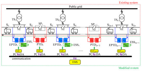
Figure 1.
The modified railway system. TS: traction substations; SP: section posts; S: section; L: load; PTD: power transferring devices; ESS: energy storage system; EPTD: PTD with an ESS; PC: power control; DA: data acquisition; LC: local controller.
After the action of the modified system, the total energy consumption of the whole railway system Pcost can be expressed as follows [36]:
where, Ptraction is the total locomotive traction power of the whole railway system; Pregeneration is the total locomotive regenerative power of the whole railway system; PES is the discharge or charge power controlled by the ESSs in the EPTDs.
Owing to NZs, with no modified system in a railway, the total energy consumption of the railway is the total locomotive traction power owing to the existence of NZs. Although RBE is generated, the electric bill of the railway will not be reduced. After adding addition of the modified system, the RBE can be shared throughout the whole railway network because the RBE can be delivered to the other power supply sections via PTDs and EPTDs. Consequently, it can be known from (1) that the total energy consumption of the railway can be reduced. Moreover, the ESSs can store and release the surplus RBE, thus enhancing the regulating means of RBE.
2.2. Description of the Control Strategy
Usually, the railway line is long, and the locations of TSs and SPs are scattered. This causes all PTDs and EPTDs in the modified system to be located in a distributed manner. Therefore, the modified system is a complex network and a large nonlinear system consisting of a number of interconnected distributed subsystems (such as PTDs and EPTDs). There are two control modes applicable to this kind of large-scale system, as shown in Figure 2, respectively, centralized control and decentralized control [39,40,41]. The centralized control has the advantages of global optimal performances and a simple control method. It can be seen from Figure 2a that all devices transmit their own information to the central controller. Consequently, the central controller can know the operation states of each power supply section in the overall railway, and perform optimal processing according to the global information. However, centralized control has high requirements on the computation ability of the processor and the communication capability, and it also has a high dependence on the central controller and communication. In order to handle this issue, a decentralized control is proposed to design LCs for each subsystem. The decentralized control structure is shown in Figure 2b. It uses only locally available information to design and implement each local controller. But the controllability of decentralized control will be limited because of the unknown operation information of other power supply sections and devices, and only achieves local instead of global optimization. Nevertheless, decentralized control does not require the sections and devices to communicate with each other, or require high calculation ability, which is a vital advantage. This paper will take advantage of this advantage.
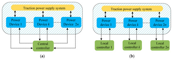
Figure 2.
Control modes (a) centralized control; (b) decentralized control.
The centralized control structure for the modified system is shown in Figure 3. In the centralized control, the LCs of each PTD and EPTD will transmit the locally collected, real-time voltage and current information to the EMS via communication. The EMS will then calculate the traction and regeneration power of each power supply section using this information, and substitute the power data into the optimization algorithm to obtain power optimization results. Then, the optimization results will be transmitted to the LCs of each PTD and EPTD via communication. Subsequently, the LCs will control the operation of all PTDs and EPTDs adopting power closed-loop, current closed-loop and voltage closed-loop [18], to realize the utilization of RBE within the railway system. It should be pointed out that in the centralized control, the LCs do not determine the transmission power reference, but control the actual transmission power of each PTD and EPTD to be consistent with the power reference value required by EMS. In the centralized control, fast calculation speed and a high data-transmission rate are required, and the optimization calculation time should not be extremely long, otherwise it will affect the real-time utilization effect of the RBE. Consequently, the performance of centralized control will strongly depend on the computational ability of the processor and its communication capability.
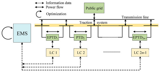
Figure 3.
Structure of centralized control for the modified system. EMS: energy management system.
Although centralized control has the advantages of simple control, simple operation and global optimal performance, its control structure is difficult to expand, and the requirements of real-time communication are extremely strict, which will bring a burden to the communication system. In the centralized control strategy, the operation of all devices strongly depends on the state of the EMS. If the EMS or communication equipment fails, it paralyzes the functioning of entire PTDs and EPTDs, as shown in Figure 4. It can be seen that incase of EMS or communication failure, the optimized regulation results will not be transmitted to the LCs of the PTDs and EPTDs, making them unable to regulate the regenerative power. Therefore, for the modified system, not only the centralized control strategy but also the decentralized control strategy should be designed to enhance the redundancy and reliability of the system.
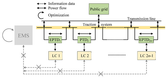
Figure 4.
Failure of the centralized control.
The decentralized control structure for the modified system can be shown in Figure 5. In the decentralized control, the LCs of each PTD and EPTD can perform the optimization calculation and independently control the power regulation of all devices. Accordingly, each PTD and EPTD has autonomous control capability, and the utilization of RBE can be realized without communication with the EMS. It can be seen that the decentralized control strategy can then reduce the burden of communication and calculation, and its advantages are obvious. However, the disadvantages of this control method are obvious too—because the LCs can only be available to local information, the decentralized control can only achieve local instead of global optimal utilization of the RBE, and economic performance for the overall system may not be the best. However, the addition of decentralized control can ensure the basic operation ability of the RBE utilization and power quality improvement in case of the centralized control failure, such that RBE can continue to be utilized within the railway system, thus providing additional guarantee for energy conservation and emission reduction of the railway.
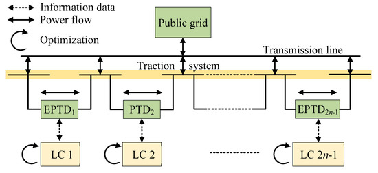
Figure 5.
Structure of the decentralized control for the modified system.
By incorporating the advantages of centralized and decentralized control strategy, this paper proposes a centralized-decentralized control for RBE utilization and power quality improvement in modified AC-fed railways. When the EMS and communication are normal, centralized control is implemented to ensure the global optimal utilization of RBE. Upon the failure of either, the system switches to decentralized control to realize the continuous utilization of RBE. Therefore, the proposal of centralized-decentralized control strategy can enhance the resilience of the modified system, indicating that the system can adapt to changing conditions and improve the ability to withstand and recover rapidly from disruptions. It will have vital significance to enhancing the redundancy and reliability of the system.
3. Centralized-Decentralized Control Strategy
Before designing the control strategy, the following assumptions were made.
- (1)
- Neglect the loss of the RBE in the flow process.
- (2)
- The capacity of the ESSs was considered to be unlimited.
Because the line loss accounts for a small proportion of all RBE, the line loss was neglected and the power transmission loss by converters alone was considered. The capacity design of the ESS will be an optimization topic, and is not the focus of this paper. Therefore, in this paper, the capacity limits of the ESSs were not considered and the capacities of the ESSs for storing regenerative energy were sufficient.
For the sake of analysis, the simplified diagram of the modified railway for RBE is drawn in Figure 6. The transmission power by EPTD and PTD is PPTD,j (j = 1, 2, ⋯, 2n); the charge and discharge power in ESS is PES,j; the feeder power of each power supply section is Pj. Defining the green arrow and the red arrow are the positive direction of PPTD,j and PES,j respectively. Defining the transmission efficiency of each converter is ηj and the charge and discharge efficiency in ESS is ηEj.
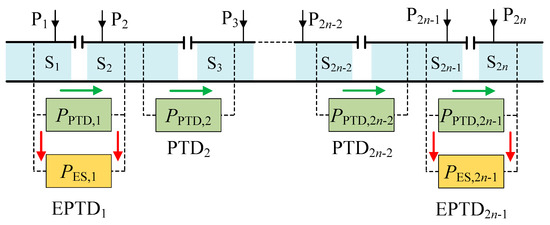
Figure 6.
The simplified electrical description for regenerative braking energy (RBE) utilization.
3.1. Centralized Control Strategy
To utilize the RBE and improve the power quality of the railway using the modified system, a centralized control algorithm was designed in this paper. In order to realize the highly efficient utilization of RBE, the control rules in [36] can be used as a reference. The steps of the designed centralized control algorithm are then described as follows:
Step 1: Adjacent transmission by single EPTD or PTD. Screening out the power supply sections where the RBE is located, and calculating the regenerative power and traction power of each power supply section. According to the power relationship, the regenerative power is delivered to the adjacent power supply section where the traction power is located by a single EPTD or PTD. Then, the transmission power PPTD_1,j of each PTD and EPTD in step 1 can be obtained.
Step 2: Transmission between two power supply sections by EPTD and PTD. After step 1, the power supply section adjacent to the section with regenerative power has no traction power. Then, recalculating the regenerative power and traction power of each power supply section. According to the residual regenerative and traction power relationship, delivering the RBE between two sections via an EPTD and a PTD. The transmission power PPTD_2,j of each PTD and EPTD in step 2 can then be obtained.
Step 3: Storage of the surplus RBE in ESS. Because the transmission efficiency to deliver regenerative power between three sections via PTDs and EPTDs is lower than it utilizing regenerative power via ESS, it is more economical to store the surplus RBE in ESSs [37]. After step 1 and step 2, if the RBE is still surplus, the surplus RBE will be stored in ESS. Then, the charge power PES_3,j in step 3 can be calculated.
Step 4: Release of the energy in ESS. To efficiently utilize RBE, it is necessary to release the previously stored RBE. After steps 1–3, no power supply section with RBE remains. If there is traction power in some sections, the previously stored RBE will be released to supply the traction power. Then, the discharge power PES_4,j in step 4 can be calculated.
Step 5: Improving the power quality of the railway. After steps 1–4, all RBE generated by locomotives and RBE stored in ESSs have been effectively utilized, and there is only the surplus of traction power in the overall railway system. Screening out the power supply sections of surplus traction power and storing the number of the power supply sections in variables j and j + 1, as shown in Figure 7. The surplus traction power in step 5 is defined as PL_5,j and PL_5,j+1. Since EPTD is located between two power supply sections of the same TS, EPTD can then eliminate three-phase current imbalance by regulating active powers PE,j,1, PE,j,2 and compensating reactive powers QE,j,1, QE,j,2. Currently, RPC is widely used to improve the power quality in AC-fed railways, so the control strategy of RPC improving power quality can be used for reference in control of EPTDj. Since the stored energy of ESSj has been released in step 4, the ESSj will not be able to supply for traction power. Therefore, ESSj will not operate in step 5.
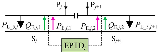
Figure 7.
Control block diagram of EPTD improving power quality.
Case 1: PL_5,j > 0, PL_5,j+1 > 0
There is traction power on both power supply sections connected to EPTDj. According to the control rules of RPC, in order to eliminate the current imbalance, first of all, the feeder power of the two power supply sections needs to be regulated to be the same as the EPTDj for delivering surplus traction power, which can relieve current imbalance to some extent. Then the corresponding reactive power is compensated according to the type of traction transformer, thus eliminating the current imbalance completely. This paper takes the V/v transformer as an example to calculate the regulating power of EPTDj.
(i) if PL_5,j < PL_5,j+1
According to the control rules of RPC improving power quality, the regulating power of EPTDj can be calculated as follows [44]:
The positive directions of active and reactive power in (2) are shown by green and red arrows in Figure 7.
(ii) if PL_5,j ≥ PL_5,j+1
The regulating power of EPTDj can then be calculated as follows:
Case 2: PL_5,j > 0, PL_5,j+1 = 0
Among the two power supply sections connected with EPTDj, only the j power supply section has traction power. To improve power quality, EPTDj needs to deliver half of the traction power from the j power supply section to the j + 1 power supply section, and then compensate the reactive power. The regulating power of EPTDj can then be calculated as follows:
Case 3: PL_5,j = 0, PL_5,j+1 > 0
Among two power supply sections connected with EPTDj, only the j + 1 power supply section has traction power. Therefore, EPTDj needs to deliver half of the traction power from the j + 1 power supply section to the j power supply section, and then compensate the reactive power. In this case, the regulating power of EPTDj can be calculated as follows:
In other cases, both power supply sections connected with EPTDj have no traction power, and the public grid does not need to supply the railway system (e.g., the case of PL_5,j = 0 and PL_5,j+1 = 0), so the railway will not cause three-phase current imbalance to the public grid. In addition, since the RBE has been utilized completely after steps 1-4, there will be no power supply sections with RBE. Therefore, in the analysis in step 5, this paper does not consider the cases of existing RBE, i.e., the case of PL_5,j < 0 or PL_5,j+1 < 0 will not occur.
Then, the regulated power references of EPTDs and PTDs and the charge and discharge power references of ESSs can be calculated using PPTD_1,j, PPTD_2,j, PES_3,j, PES_4,j and PE,j,1, PE,j,2, QE,j,1, QE,j,2. These references are calculated by EMS and are delivered to the PTDs and EPTDs via bidirectional communication equipment. Finally, the utilization of RBE and power quality improvement in the railway can be realized by the proposed centralized control strategy. The control diagram of the centralized control strategy is shown in Figure 3.
3.2. Decentralized Control Strategy
In the centralized control, the operation of PTD and EPTD largely depends on the state of the EMS and communication. If the EMS or communication equipment fails, the utilization effect of RBE is seriously affected. To tackle this issue, a decentralized control strategy is proposed in this paper. In case of the centralized control strategy failure, the LCs can still perform the decentralized control strategy to control the PTDs and EPTDs by themselves, thus enabling the RBE to continue to be utilized within the railway system.
To design the decentralized control strategy, the running state of the PTDs and EPTDs must be first analyzed. The running state of the PTDs and EPTDs can be shown in Figure 8. The locomotive load powers in Sj and Sj+1 are respectively defined as PL,j and PL,j+1. The directions of arrows are the positive direction of power. Then, the feeder power of j section and j + 1 section can be obtained as follows:
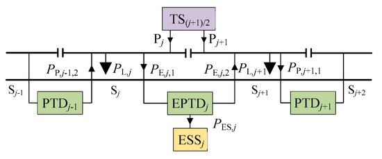
Figure 8.
Power quality improvement by EPTD.
Then, according to (6), the total power of TS can be calculated as follows:
It can be seen from (7) that the transmission power of EPTDj has no influence on the total power of TS, and the total power of TS will be affected by the transmission power of PTDj-1, PTDj+1 and charge and discharge power of ESSj.
According to the principle of control strategy to improve the power quality in [34], the regulated power of EPTDj eliminating three-phase current imbalance can be expressed as follows:
Then, after EPTDj eliminating three-phase current imbalance, the feeder power of the two power supply sections will be expressed as follows:
Compared with (7) and (9), it can be found that the effect of EPTDj on the overall feeder power is similar to that when running according to the centralized control strategy and according to the control strategy of eliminating three-phase current imbalance. Furthermore, it also can be seen from (8) that the active powers of j and j + 1 power supply sections can be automatically balanced when EPTDj implements the control strategy of eliminating three-phase current imbalance. That means, when eliminating three-phase current imbalance, EPTDj can automatically deliver RBE from the section with RBE to the section with traction power, realizing the automatic utilization of RBE. This paper will make full use of this characteristic of EPTD to design the decentralized control strategy.
Besides, it can also be seen from (7) that the overall feeder power of TS will be affected by the regenerative power delivered by PTDj-1, PTDj+1 and the charging and discharging power of ESSj. Therefore, in order to realize the utilization of RBE, it is necessary to control the regulated power of the PTDs and the charge and discharge power of the ESSs in the decentralized control strategy. Then, a decentralized control principle was designed in this paper, and its principles are as follows:
- (1)
- EPTD automatically performs the function of improving the power quality to realize the automatic utilization of RBE between two power supply sections in the same TS, and according to the locomotive load power of two power supply sections, calculates the charge and discharge power of EES.
- (2)
- PTD automatically performs the function of regulating the RBE to realize the utilization of RBE between two power supply sections in the adjacent TSs, and according to the locomotive load power of two power supply sections, calculates the regulated power of PTD.
Using the above mentioned principles, the LCs can automatically control each PTD and EPTD without establishing communication with each other, so as to ensure that the RBE can still be utilized when the centralized control fails.
According to the decentralized control principles, the decentralized control of the PTDs and EPTDs is designed as follows:
(a) the control strategy of LCs in PTDs
The operation states of power supply sections on both sides of PTDj are shown in Figure 9. It needs to judge the locomotive load power of two power supply sections to calculate the regulated power of PTDj.
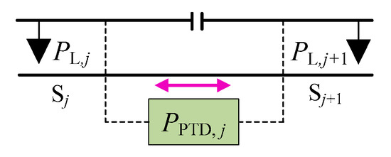
Figure 9.
Power quality improvement by EPTD.
Case 1: PL,j > 0, PL,j+1 > 0
No transmission.
Case 2: PL,j ≤ 0, PL,j+1 ≤ 0
No transmission.
Case 3: PL,j > 0, PL,j+1 < 0
The regenerative power in the j + 1 power supply section is delivered to the j power supply section. The RBE should be maximized transmission. Therefore, the regulated power PPTD,j can be calculated as follows:
Case 4: PL,j < 0, PL,j+1 > 0
The regenerative power in the j power supply section is delivered to the j + 1 power supply section. Therefore, the regulated power PPTD,j can be calculated as follows:
(b) the control strategy of LCs in EPTDs
The operation states of power supply sections on both sides of EPTDj are shown in Figure 10. It needs to judge the locomotive load power of two power supply sections to calculate the regulated power of EPTDj and the charge and discharge power of ESSj.
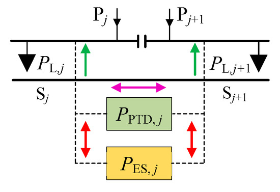
Figure 10.
Power quality improvement by EPTD.
Since EPTDj can automatically deliver RBE from the section with RBE to the section with traction power when eliminating three-phase current imbalance, in the control process of EPTDj, the regulating power of EPTDj can always be calculated as follows:
It can be seen from (12) that EPTDj does not need to judge and quantify the locomotive load power, but only needs to detect the locomotive load power on both power supply sections and substitute it to (12) to realize the utilization of RBE and improve power quality. However, whether ESSj in EPTDj needs to be charged or discharged, as well as the value of its charge and discharge power, needs to be determined according to the locomotive load power on both power supply sections and the capacity of ESSj. Subsequently, the control strategy of ESSj is designed as follows:
Case 1: PL,j > 0, PL,j+1 > 0
There is traction power on both power supply sections connected to EPTDj. If there is surplus RBE stored in ESSj in EPTDj, it will be released to power the traction power on both power supply sections. If there is sufficient RBE, ESSj will release the energy just equal to power the traction power. If the energy stored in ESSj in EPTDj is less than the traction power, the energy stored in the ESSj can be released completely. Then, the discharge power of EPTDj can be calculated as follows:
where EES,j is the energy stored in ESSj.
Case 2: PL,j < 0, PL,j+1 < 0
There is regenerative power in both power supply sections connected to the EPTDj. If the available capacity of ESSj in EPTDj is sufficient, all the RBE in both power supply sections will be stored in ESSj in EPTDj. If the available capacity of ESSj in EPTDj is less than the regenerative power, only the RBE equal to the available capacity of ESSj will be stored in ESSj. Then, the charge power of EPTDj can be calculated as follows:
where CES,j is the overall capacity of the ESSj.
Case 3: PL,j > 0, PL,j+1 < 0
(i) if |PL,j|≥ |PL,j+1|
In this situation, the traction power on the j power supply section is more than the regenerative power on the j + 1 power supply section. First of all, the regenerative power is delivered from the j + 1 power supply section to the j power supply section to supply the traction power, and then the remaining traction power on the j power supply section will be supplied by ESSj. If there is sufficient RBE, ESSj will release the energy just equal to power the traction power. If the energy stored in ESSj in EPTDj is less than the traction power, the energy stored in ESSj can be released completely. Then, the discharge power of EPTDj can be calculated as follows:
(ii) if |PL,j|< |PL,j+1|
In this situation, the traction power on the j power supply section is less than the regenerative power on the j + 1 power supply section. First of all, the regenerative power is delivered from the j + 1 power supply section to the j power supply section to supply the traction power, and then the surplus regenerative power on the j + 1 power supply section will be stored in the ESSj. If the available capacity of ESSj in EPTDj is sufficient, the surplus RBE in the j + 1 power supply section will be stored in the ESSj in EPTDj. If the available capacity of ESSj in EPTDj is less than the regenerative power, only the RBE equal to the available capacity of ESSj will be stored in ESSj. Then, the charge power of EPTDj can be calculated as follows:
Case 4: PL,j < 0, PL,j+1 > 0
(i) if |PL,j|≥ |PL,j+1|
In this situation, the regenerative power on the j power supply section is more than the traction power on the j + 1 power supply section, similar to case 3(ii). After delivering the regenerative power via EPTDj, the surplus regenerative power will be stored in the ESSj. The charge power of EPTDj can be calculated as follows:
(ii) if |PL,j|< |PL,j+1|
In this situation, the regenerative power on the j + 1 power supply section is less than the traction power on the j + 1 power supply section, similar to case 3(i). After delivering the regenerative power via EPTDj, the remaining traction power will be supplied by the ESSj. The discharge power of EPTDj can be calculated as follows:
The LCs use the above decentralized control steps to control each PTD and EPTD separately, which can realize the utilization of RBE. In the decentralized control, the LCs can autonomously operate without communication with the EMS. Each LC independently uses the local available information to control the operation of each PTD and EPTD. Nevertheless, the decentralized control can achieve only the local instead of global optimal utilization of RBE. In fact, the decentralized control strategy is similar to the first step in the centralized control strategy, so the decentralized control cannot achieve the global optimal utilization of RBE. Due to the independent operation between the LCs, there may be surplus RBE in a certain local area. At this time, the surplus RBE can only be fed back to the public grid, so that part of the RBE cannot be utilized within the railway. Accordingly, the disadvantage of decentralized control is that it cannot achieve global optimal control, but even so, it can still ensure a part of the RBE can be utilized within the railway. Therefore, the addition of decentralized control can make the modified system still operate when the centralized control strategy fails, thus enhancing the reliability of the modified system.
4. Load Power Detection and Regulated Power Reference Calculation
To ensure the centralized-decentralized control strategy can effectively utilize the RBE, it is necessary to accurately detect the load power of all locomotives, and further calculate the regulating power reference of all PTDs and EPTDs according to the load power. The simplified model of the modified railway system is shown in Figure 11.
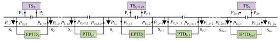
Figure 11.
Simplified model of the modified railway system and its electrical description.
It can be seen that after the operation of the modified system, the load power in each power supply section will be affected by the regulated power of the PTDs and EPTDs, so the load power of locomotives in each power supply section cannot be directly detected. If the power detection device is added to each electric locomotive and transmitted to the controller via communication equipment, the load power of each locomotive will be obtained. However, there are many electric locomotives in each power supply section at the same time. If the power detection device is added to each electric locomotive, it will bring a huge cost burden. Moreover, due to the influence of communication speed, it is not guaranteed that the load power of each locomotive at the same time can be simultaneously transmitted to the controller. If the controller uses the load power data of the locomotive at different times for calculation, the calculated load power of the locomotive may deviate from the real value, resulting in problems in the utilization of the RBE. Therefore, this paper further proposes the detection method of locomotive load power and the calculation method of regulated power reference under the centralized-decentralized control strategy to provide support for the effective operation of the modified system.
4.1. Detection Principle in Centralized Control
The data information needed to be detected in each power supply section under centralized control is shown in Figure 12. uj (j = 1, 2, ⋯, 2n) is the voltage on each power supply section; iLP,j is the section load current on each power supply section; iP,j,1 and iP,j,2 are the regulated current controlled by PTDj. It can be seen that the section load current on each power supply section is affected by the locomotive load power and regulated power of the PTDs. In order to calculate the locomotive load power and the regulated power reference of the PTDs and the EPTDs in the centralized control, it is necessary to detect the data information of uj, iLP,j, iP,j,1, iP,j,2 using voltage and current transformers.
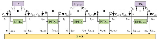
Figure 12.
The data information needed to be detected in centralized control.
First of all, according to the above voltage and current information detected by transformers, the section load power PLP,j on each power supply section and the regulated power PP,j,1 and PP,j,2 controlled by PTDj is calculated.
The voltage on each power supply section can be described as follows:
where, Uj is the root mean square (RMS) of voltage on each power supply section; ϕj is the angle of voltage on each power supply section; ω is the angular frequency of voltage.
Currently, the power factor of electric locomotives is very high, so the reactive power generated by locomotives is not considered in this paper. Then, the section load current on each power supply section can be described as follows:
where, ILP,j is the RMS of fundamental current; ILh,j is the RMS of harmonic current; ϕLh,j is the angle of harmonic current; h is the harmonic order.
According to (19) and (20), the instantaneous section load power on each power supply section is calculated as follows:
It can be seen from (21) that the section load power contains a DC component and an AC component. Using low pass loop (LPF), the DC component of the section load power can be obtained as follows:
Combining (19)–(22), the detection block diagram can be obtained as shown in Figure 13. The voltage phase of each power supply section can then be obtained by the phase locked loop (PLL), then the voltage RMS of each power supply section can be obtained by ab-dq coordinate transformation. Subsequently, the instantaneous section load power can be obtained by combining the section load current with the voltage phase. Then, the section load power on each power supply section can be obtained using LPF. Using the same method, the regulated power of the PTDs can also be obtained.
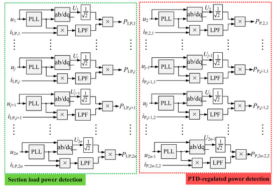
Figure 13.
Detection block diagram of section load power and PTD-regulated power in centralized control. PLL: phase locked loop; LPF: low pass loop.
Then, according to the Figure 13, the section load power and PTD-regulated power can be calculated. Since the section load power is affected by the locomotive load power and PTD-regulated power, according to the law of Kirchhoff, the locomotive load power can be calculated by the use of the section load power and PTD-regulated power. The locomotive load power can be calculated as follows:
where, the positive direction of each power is shown in Figure 12.
Since the first power supply section and 2n-th power supply section are not connected with the PTD, the detected section load power is the locomotive load power. The second to (2n − 1)-th power supply sections are connected with the PTDs, so after detecting the section load power, it is necessary to remove the PTD-regulated power to obtain the locomotive load power. According to (23), the detection method of the locomotive load power can be obtained, as shown in Figure 14.
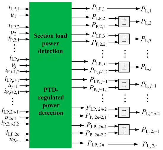
Figure 14.
Detection block diagram of locomotive load power in centralized control.
It should be noted that before the modified system runs, the PTDs have not delivered the RBE, defining this time as t = 0. When t = 0, the regulated power of all the PTDs PP,2,1 =⋯= PP,j-1,1 = PP,j-1,2 =⋯= PP,2n-2,2 = 0. At this time, the detected section load power on each power supply section is the locomotive load power.
After calculating the locomotive load power on each power supply section, the regenerative power and traction power on each power supply section is known. Using the centralized control strategy in Section 3.1, the regulated power reference of each PTD and EPTD can be calculated. The calculation process is shown in Figure 15.
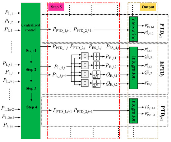
Figure 15.
Calculation block diagram of regulated power reference in centralized control.
4.2. Detection Principle in Decentralized Control
(a) Detection principle of PTDs
It is known from the analysis in Section 4.1 that the section load current on each power supply section is affected by the locomotive load power and regulated power of the PTDs. Therefore, in decentralized control, to accurately calculate the locomotive load power and obtain the regulated power of the PTDs, it needs to detect the voltage, the section load current and the PTD-regulated current on both power supply sections connected to the PTDs using voltage and current transformers. The data information needed to be detected in the decentralized control of PTD is shown in Figure 16.
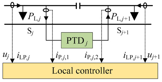
Figure 16.
The data information needed to be detected in decentralized control of the PTD.
It can be seen from Figure 16 that in the j and j + 1 power supply sections on both sides of PTDj, the voltage uj, uj+1, the section load current iLP,j, iLP,j+1 and the PTD-regulated current iP,j,1, iP,j,2 need to be detected. Then, using voltage and current information detected by transformers, the section load power PLP,j, PLP,j+1 on the j and j + 1 power supply sections and the regulated power PP,j,1 and PP,j,2 controlled by PTDj is calculated. Subsequently, the locomotive load power PL,j, PL,j+1 can be calculated using PLP,j, PLP,j+1, PP,j,1, PP,j,2. Then, the regulated power of PTDj can be obtained by substituting PL,j, PL,j+1 into the decentralized control strategy of the PTD. The detection block diagram is shown in Figure 17. According to the decentralized control strategy and detection method, each PTD can realize the delivery of RBE between adjacent power supply sections.
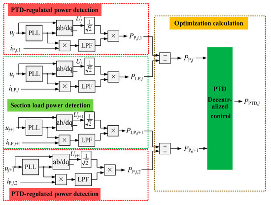
Figure 17.
Detection block diagram in decentralized control of PTD.
(b) Detection principle of EPTDs
Since EPTDs can automatically deliver RBE from the section with RBE to the section with traction power when eliminating three-phase current imbalance. Therefore, EPTDs do not need to know the locomotive load power accurately, and only detecting the section load power on both power supply sections connected to the EPTDs is sufficient. Then, by substituting the section load power to (12), the RBE on both power supply sections connected to the EPTDs can be automatically utilized. However, the charge and discharge power of the ESSs in the EPTDs need to be calculated according to the section load power. To calculate the section load power, the voltage and the section load current on both power supply sections connected to the EPTDs as well as the energy stored in the ESSs need to be detected. The data information needed to be detected in the decentralized control of the EPTD is shown in Figure 18.
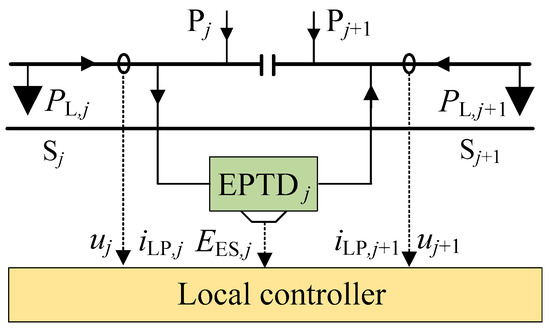
Figure 18.
The data information needed to be detected in decentralized control of the EPTD.
It can be seen from Figure 18 that in the j and j + 1 power supply sections on both sides of EPTDj, the voltage uj, uj+1, the section load current iLP,j, iLP,j+1 and the energy EES,j stored in ESSj need to be detected. Then, using voltage and current information detected by transformers, the section load power PLP,j, PLP,j+1 on j and j + 1 power supply section is calculated. Combined with PLP,j, PLP,j+1, EES,j and the overall capacity CES,j of ESSj, the charge and discharge power PES,j of ESSj is calculated by the use of the decentralized control strategy of the EPTD. Then, the regulated power of EPTDj in the decentralized control strategy can be obtained. The detection block diagram is shown in Figure 19.
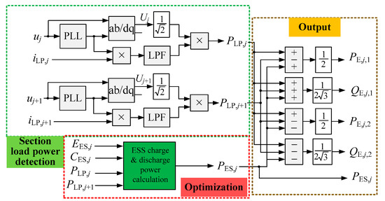
Figure 19.
Detection block diagram in decentralized control of the EPTD.
Finally, by using the centralized-decentralized control strategy in Section 3 and the load power detection method and regulated power reference calculation method in Section 4, the centralized-decentralized control to the modified system can be realized, ensuring the utilization of RBE and power quality improvement in the railway system. Then, the flow chart of centralized- decentralized control can be drawn, as shown in Figure 20.
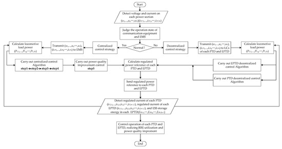
Figure 20.
Flow chart of centralized-decentralized control.
The proposed centralized-decentralized control strategy can enhance the resilience of the modified system, and enhance the ability to resist risks and recoverability of utilizing RBE from disruptions. It will have vital significance to the safe operation of the modified railway system.
5. Results Verification and Analysis
To evaluate the effectiveness of the proposed centralized-decentralized control strategy, a modified railway system consisting of four TSs and eight power supply sections is considered. The diagram of the modified railway system is shown in Figure 21. The transmission efficiency and the charge and discharge efficiency of the EPTDs and PTDs were randomly generated in MATLAB, as shown in Table 1. Four groups of different locomotive power data in eight supply power sections were generated in MATLAB to verify the effectiveness of the centralized control and decentralized control as well as compare their performance, as shown in Table 2. The locomotive power ranged from -10 kW to 10 kW. The centralized-decentralized algorithm was realized in MATLAB.
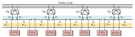
Figure 21.
The diagram of the modified railway system.

Table 1.
Converter efficiency.
Table 2.
Four groups of different locomotive power data in eight supply power sections (MW).
5.1. Feasibility Evaluation of the Centralized-Decentralized Control Strategy
(1) Case 1
The centralized and decentralized control strategies are used to control the traction power and regenerative braking energy data in case 1. The regulation results are shown in Table 3, and Figure 22 can be drawn according to the results in Table 3.
Table 3.
Feeder power before and after regulation under case 1 (MW).
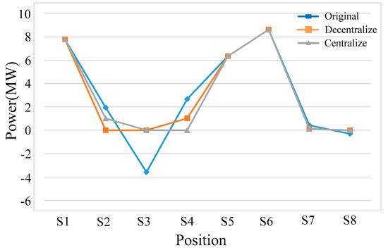
Figure 22.
Results before and after control in case 1.
It can be seen from Figure 22 that the results of decentralized control and centralized control are similar, indicating that there is no significant difference between decentralized control and centralized control in case 1. Under both strategies, the RBE is effectively utilized within the railway system, and the overall energy saving results of the railway system is equivalent. Nevertheless, the results of decentralized control are slightly different from those of centralized control. It can be seen from Table 3 that in the decentralized control, the RBE in S3 is preferentially delivered to S2; while in the centralized control, the RBE in S3 is preferentially delivered to S4. The reason for this slight difference is that the centralized control strategy can achieve global optimization, and the EMS will regulate the RBE according to the converter efficiency. Because the efficiency of EPTD3 is higher than that of PTD2, the RBE in S3 will be preferentially delivered to S4 to supply traction power in the centralized control. By contrast, in the decentralized control, since the LCs of each converter do not know the efficiency and operation state of other converters, each PTD and EPTD will run autonomously. Therefore in the decentralized control, the RBE in S3 is preferentially delivered to S2 by PTD2 without considering the converter efficiency, rather than adopting the converter with the higher efficiency to preferentially deliver. As analyzed in Section 2, the decentralized control can achieve only the local instead of global optimal utilization of RBE, and the economic performance for the overall system may not be the best, which is the constraint of decentralized control. However, it can be seen from the verification results that although the decentralized control has shortcomings, it can also effectively utilize the RBE, which proves the effectiveness of the proposed decentralized control.
(2) Case 2
The power data in case 2 are separately controlled by the centralized and decentralized control strategies. The regulation results are shown in Table 4, and the corresponding waveform is shown in Figure 23. It is obvious to see that the regulated results under decentralized control and centralized control are the same, and the RBE in the railway system has been effectively utilized. It indicates that in some cases, the decentralized control strategy can achieve exactly the same effect as the centralized control.
Table 4.
Feeder power before and after regulation under case 2 (MW).
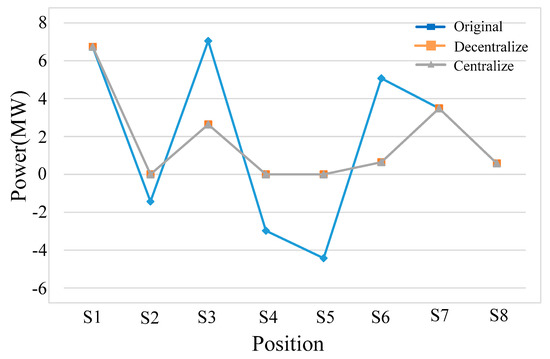
Figure 23.
Results before and after control in case 2.
(3) Case 3
The power data in case 3 are controlled by the centralized and decentralized control strategies separately. The regulation results are shown in Table 5, and the corresponding waveform is shown in Figure 24. It can be seen from Figure 24 that the centralized control strategy can make full use of the RBE, while there is still surplus RBE after the decentralized control. The reason resulting in this phenomenon is the influence of the control rules of decentralized control and centralized control. The locomotives in S6 generates a large RBE, but the adjacent sections S5 and S7 cannot absorb so much RBE. Because the decentralized control can only deliver RBE to the adjacent section, the RBE in S6 can only be residual after implementing the decentralized control. At this time, if the available capacity of ESS5 in EPTD5 is sufficiently large, the surplus RBE can be stored in the ESS5. By contrast, the centralized control strategy can deliver the RBE in S6 to S8, realizing the full utilization of all RBE in the railway system, thereby saving energy storage capacity. It can be seen from the comparison that under case 3, the energy storage capacity required by decentralized control is more than that required by centralized control. So, in order to make all the RBE fully utilized in the railway system during decentralized control, the capacity of the required ESS will be increased. When the capacity of ESS is designed according to the centralized control, under the same capacity of ESS, the decentralized control cannot make all the RBE fully utilized inside the railway system, and there will be a certain amount of RBE fed back to the public grid. This is another constraint of the decentralized control.
Table 5.
Feeder power before and after regulation under case 3 (MW).
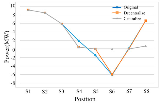
Figure 24.
Results before and after control in case 3.
(4) Case 4
The power data in case 4 are controlled by the centralized and decentralized control strategies separately. The regulation results are shown in Table 6, and the corresponding waveform is shown in Figure 25. When the ESSs is not running, there is surplus RBE after both the centralized control and decentralized control. However, the surplus RBE in the centralized control is less than that in the decentralized control, which is caused by the shortcoming mentioned in case 3. After that, the surplus RBE will be stored in the ESSs, but the ESSs will store less energy in the centralized control strategy.
Table 6.
Feeder power before and after regulation under case 4 (MW).
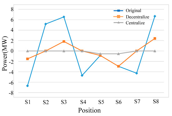
Figure 25.
Results before and after control in case 4.
(5) Power Quality Improvement
Furthermore, taking the power data of S1 and S2 in case 1 as an example to verify the function of power quality improvement: the voltage and current waveforms in the public grid under the centralized and decentralized control strategies are separately shown in Figure 26a,b. The corresponding harmonic spectrum results (taking A-phase current as an example) are shown in Figure 27. Before the operation of the modified system, the original data in S1 is 7.77211MW, and that in S2 is 1.93986MW. From stage 1 in Figure 26a,b, it can be seen that if it does not perform the function of power quality improvement, the railway grid will cause three-phase current imbalance in the public grid due to the influence of the traction transformer. From stage 2 in Figure 26a,b, it can be seen that under the action of the function of power quality improvement in centralized and decentralized control, although the RBE in railway is not delivered, the three-phase current imbalance in the public grid can still be eliminated. It can be seen from stage 2 that the grid voltage and current are in the same phase, indicating the function of power quality improvement will not cause reactive power pollution while eliminating the three phase current imbalance. It has proved the effectiveness of the function of power quality improvement in centralized and decentralized control. Moreover, it can be seen from Figure 27a,c that the total harmonic distortions (THD) of the grid AC current under decentralized and centralized control are 1.24% and 1.25% respectively. From stage 3 in Figure 26a,b, it can be seen that after using decentralized control or centralized control to control the RBE, the current provided by the public grid to the railway grid is reduced, which means that the traction energy consumption of the railway is greatly reduced. Meanwhile, the three-phase current can still keep balance while effectively utilizing the RBE. It has verified the effectiveness of the functions of RBE utilization and power quality improvement and their cooperative operation under decentralized control and centralized control. Alternatively, it can be seen from Figure 27b,d that the THDs of the grid AC current under decentralized and centralized control are 1.48% and 1.32% respectively. By comparing the green areas in Figure 26a,b, a slight difference between decentralized control and centralized control is that the effect of energy saving is different. Because the RBE in S3 is delivered to S2 in decentralized control, the power data in S2 is 0 MW after implementing the decentralized control. In contrast, the RBE in S3 is delivered to S4 in the centralized control, so the power data in S2 is 1.01428 MW after implementing the centralized control. However, no matter how much power is in both sections, the decentralized control and centralized control can realize the function of the power quality improvement.
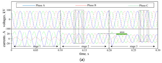
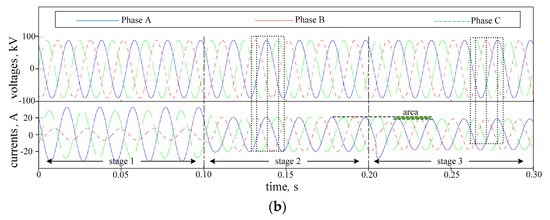
Figure 26.
Results of power quality improvement under decentralized control and centralized control (a) decentralized control; (b) centralized control.
Figure 27.
The harmonic spectrum results of power quality improvement under decentralized control and centralized control (a) stage 2 in decentralized control; (b) stage 3 in decentralized control; (c) stage 2 in centralized control; (d) stage 3 in centralized control. THD: total harmonic distortions.
Moreover, take the power data of S1 and S2 in case 4 is an example of performing the centralized and decentralized control respectively, to further verify the effectiveness of power quality improvement function in RBE mode. The control results are shown in Figure 28a,b separately. The corresponding harmonic spectrum results (taking A-phase current as an example) are shown in Figure 29. Before the operation of the modified system, the original data in S1 is 6.69996 MW, and the original data in S2 is 5.17845 MW and the regenerative power surpasses traction power. From stage 1 in Figure 28a,b, it indicates that the imbalance of three-phase current is extremely severe in RBE mode. From stage 2 in Figure 28a,b, the three-phase current imbalance has been eliminated under the action of the function of power quality improvement in the centralized and decentralized controls. In addition, the grid voltage and current are in the opposite phase, indicating that the RBE will be fed back to the public grid by traction transformers if no other measures are taken. Moreover, it can be seen from Figure 29a,b that the THDs of the grid AC current under decentralized and centralized control are 2.34% and 2.33% respectively. From stage 3 in Figure 28a, it can be seen that the RBE will still be fed back to the public grid under the action of decentralized control. The reason for this result is that the LCs can access only local information, thus, the surplus RBE in S1 will not be delivered to S3 in the decentralized control. Therefore, in decentralized control, the THD of stage 3 are the same as those of stage 2. At stage 3 in Figure 28b, the surplus RBE in S1 is consumed. The reason is that the EMS can know the power information of all power supply sections, thus, in the centralized control, the EMS can perform a global optimization to regulate the RBE flow. Additionally, the surplus RBE in S1 can be delivered to S3 to be consumed, and realizing the RBE is effectively utilized within the railway network. The results show that, in RBE mode, the power quality of the railway can also be improved.
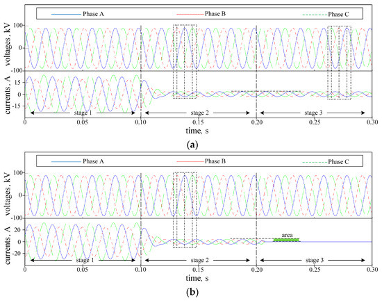
Figure 28.
Results of power quality improvement under decentralized control and centralized control (a) decentralized control; (b) centralized control.
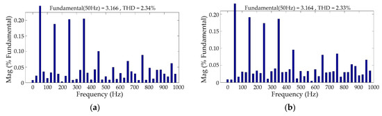
Figure 29.
The harmonic spectrum results of power quality improvement under decentralized control and centralized control (a) stage 2 in decentralized control; (b) stage 2 in centralized control.
5.2. Energy Storage Performance Comparison of the Centralized and Decentralized Control Strategy
From the above analysis, we can see that different control strategies have different requirements for the capacity of energy storage in the modified system. To reveal the difference, furthermore, a comparison between the storage energy in the centralized control and that in the decentralized control was made in MATLAB to compare the performance of the centralized and decentralized control strategy. The locomotive power data used in MATLAB adopts the same data in [37], and the comparison results are shown in Figure 30. It can be seen that the storage energy of the ESS adopting the centralized control is less than that in decentralized control, further verifying the constraint that decentralized control needs more ESS. Although the decentralized control has shortcomings, the decentralized control can ensure the basic operation ability of RBE utilization and power quality improvement in case of the centralized control failure, thus enhancing the reliability of the modified railway system.
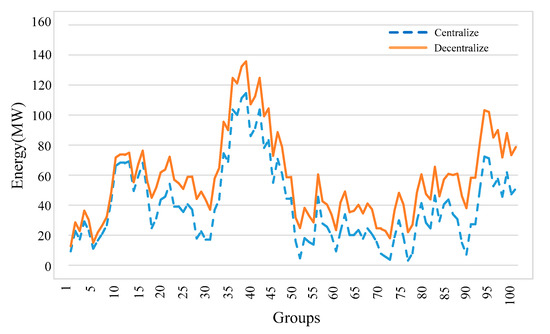
Figure 30.
A comparison results of storage energy between the centralized control and the decentralized control.
In addition, a comparison of storage energy between the modified system adopting centralized control as well as the decentralized control and the system with ESSs alone is also made in MATLAB. It can be seen from Figure 31 that, no matter which control is adopted in centralized control or decentralized control, the storage energy of the ESS adopting the modified system is less than that adopting the system with ESSs alone. It is mentioned in [37] that the modified system has a great superiority in the use of ESS. This comparison result indicates the RBE utilization scheme adopting the modified system is obviously superior to the scheme adopting the system with ESSs alone in terms of the capacity and cost of ESS, and it also verifies the feasibility of the proposed centralized-decentralized control strategy. Although the storage energy of ESS in decentralized control has slightly increased, it is still lesser than the storage energy of the system with ESSs alone. Therefore, the application of a centralized-decentralized control strategy can still make the modified system maintain advantages in terms of the capacity and cost of ESS.
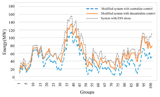
Figure 31.
A comparison of results of storage energy between the modified system adopting centralized control as well as the decentralized control and the system with ESSs alone.
To summarize, the feasibility and the performance of centralized and decentralized control are verified in Section 5. Though the proposed centralized-decentralized control strategy, RBE utilization and power quality improvement in the railway system can be achieved. Also, when the EMS and communication are normal, the centralized control is implemented to ensure the global optimal utilization of RBE. In case of failure, the system switches to decentralized control to realize the continuous utilization of RBE. By the proposed control strategy, the modified railway system can continuously utilize the RBE without intermission, and the reliability and safety of the system will be enhanced, providing further guarantee for energy conservation and emission reduction of the railway.
It needs to be noted that the modified system can also realize the harmonic compensation control. However, because this function is not used in the design of the centralized-decentralized control strategy, this function is not included in power quality improvement control. If the reader or designer wants to add the harmonic elimination control to the modified system, they can refer to the calculation process for harmonic compensation in [43] to calculate reference power. The function of harmonic compensation will be no longer described in detail in this paper.
6. Conclusions
The modified AC-fed railway system with energy-storage-based smart electrical infrastructure creates more opportunities and controllability for smart railway systems. With respect to the modified AC-fed railway system, this paper proposes a centralized-decentralized control strategy for RBE utilization and power quality improvement. In the centralized control strategy, the optimization calculation process is performed in the centralized controller, namely EMS in this paper, and the power regulation references of all PTDs and EPTDs are uniformly dispatched by EMS with the advantage of global optimal performances. In the decentralized control strategy, the power regulation references of all PTDs and EPTDs will be calculated in their respective LCs without mutual communication, but only with local optimal performances. When the EMS and communication are normal, centralized control is implemented to ensure the global optimal utilization of RBE and power quality improvement. If the EMS or communication equipment failed, the system switches to decentralized control to continuously realize the utilization of RBE and power quality improvement. The combination of centralized control and decentralized control will improve the reliability and redundancy of the modified AC-fed railway system.
Firstly, to realize the centralized-decentralized control strategy, the control principles and implementation process of the centralized control and decentralized control were given respectively. By the use of the control principles and implementation process, the centralized-decentralized control strategy can be performed to utilize the RBE and improve power quality.
Furthermore, considering the influence of the regulated power of each PTD and EPTD on locomotive load power, to accurately detect the load power of all locomotives and make sure the centralized-decentralized control strategy can effectively operate, a method of load power detection and regulated power reference calculation was proposed. Then, combining the centralized-decentralized control strategy principle with the load power detection method and regulated power reference calculation method, the centralized-decentralized control strategy can be effectively implemented.
Finally, the effectiveness of the proposed strategy was verified in a case of a modified railway system consisting of four traction substations and eight power supply sections. The results showed that the RBE in the railway can be efficiently utilized and the power quality can be improved using the proposed centralized-decentralized control strategy. The proposal of a centralized-decentralized control strategy can enhance the resilience of the modified railway system, and the ability to adapt to changing conditions. It also can improve the ability to withstand and recover rapidly from disruptions. The work done in this paper is the continuation of the research in [36] and will have vital significance to enhancing the redundancy and reliability of the modified railway system, and providing further guarantee for the energy conservation and consumption reduction of the railway systems.
Author Contributions
Z.G. and Q.L. designed the research; C.W. and B.H. helped with validation and formula derivation; Z.G. and C.C. finished the verification; Z.G. wrote the paper. All authors have read and agreed to the published version of the manuscript.
Funding
This work was funded in part by [the Shenhua Group Co., Ltd., Science and Technology Innovation Projects] grant number [CSIE16024877], and in part by [the National Natural Science Foundation of China under] grant number [51577187].
Conflicts of Interest
The authors declare no conflict of interest.
References
- Serrano-Jiménez, D.; Abrahamsson, L.; Castaño, S.P.; Sanz-Feito, J. Electrical railway power supply systems: Current situation and future trends. Int. J. Electr. Power Energy Syst. 2017, 92, 181–192. [Google Scholar] [CrossRef]
- Hayashiya, H.; Yokokawa, S.; Iino, Y.; Kikuchi, S.; Suzuki, T.; Uematsu, S.; Sato, N.; Usui, T. Regenerative energy utilization in a.c. traction power supply system. In Proceedings of the 2016 IEEE International Power Electronics and Motion Control Conference (PEMC), Varna, Bulgaria, 25–28 September 2016; pp. 1125–1130. [Google Scholar]
- Ronanki, D.; Singh, S.A.; Williamson, S. Comprehensive Topological Overview of Rolling Stock Architectures and Recent Trends in Electric Railway Traction Systems. IEEE Trans. Transp. Electrif. 2017, 3, 724–738. [Google Scholar] [CrossRef]
- The International Energy Agency (IEA) and the International Union of Railways (UIC). Railway Handbook: Energy Consumption and CO2 Emissions. Available online: https://www.iea.org/reports/railway-handbook-2017 (accessed on 3 October 2019).
- Douglas, H.; Roberts, C.; Hillmansen, S.; Schmid, F. An assessment of available measures to reduce traction energy use in railway networks. Energy Convers. Manag. 2015, 106, 1149–1165. [Google Scholar] [CrossRef]
- Ronanki, D.; Williamson, S. Modular Multilevel Converters for Transportation Electrification: Challenges and Opportunities. IEEE Trans. Transp. Electrif. 2018, 4, 399–407. [Google Scholar] [CrossRef]
- Ronanki, D.; Williamson, S. Evolution of Power Converter Topologies and Technical Considerations of Power Electronic Transformer-Based Rolling Stock Architectures. IEEE Trans. Transp. Electrif. 2018, 4, 211–219. [Google Scholar] [CrossRef]
- Bocharnikov, Y.; Tobias, A.; Roberts, C.; Hillmansen, S.; Goodman, C. Optimal driving strategy for traction energy saving on DC suburban railways. IET Electr. Power Appl. 2007, 1, 675. [Google Scholar] [CrossRef]
- Li, L.; Dong, W.; Ji, Y.; Zhang, Z.; Tong, L. Minimal-Energy Driving Strategy for High-Speed Electric Train With Hybrid System Model. IEEE Trans. Intell. Transp. Syst. 2013, 14, 1642–1653. [Google Scholar] [CrossRef]
- D’Arco, S.; Piegari, L.; Tricoli, P. Comparative Analysis of Topologies to Integrate Photovoltaic Sources in the Feeder Stations of AC Railways. IEEE Trans. Transp. Electrif. 2018, 4, 951–960. [Google Scholar] [CrossRef]
- Hernandez, J.; Sutil, F.S. Electric Vehicle Charging Stations Feeded by Renewable: PV and Train Regenerative Braking. IEEE Lat. Am. Trans. 2016, 14, 3262–3269. [Google Scholar] [CrossRef]
- Zhu, X.; Hu, H.; Tao, H.; He, Z. Stability Analysis of PV Plant-Tied MVdc Railway Electrification System. IEEE Trans. Transp. Electrif. 2019, 5, 311–323. [Google Scholar] [CrossRef]
- Aguado, J.A.; Racero, A.J.S.; De La Torre, S. Optimal Operation of Electric Railways With Renewable Energy and Electric Storage Systems. IEEE Trans. Smart Grid 2016, 9, 993–1001. [Google Scholar] [CrossRef]
- Boudoudouh, S.; Maaroufi, M.; Maaroufi, M. Renewable Energy Sources Integration and Control in Railway Microgrid. IEEE Trans. Ind. Appl. 2018, 55, 2045–2052. [Google Scholar] [CrossRef]
- Tian, Z.; Chen, M.; Weston, P.; Hilmansen, S.; Zhao, N.; Roberts, C.; Chen, L. Energy evaluation of the power network of a DC railway system with regenerating trains. IET Electr. Syst. Transp. 2016, 6, 41–49. [Google Scholar] [CrossRef]
- Khodaparastan, M.; Mohamed, A.; Brandauer, W. Recuperation of Regenerative Braking Energy in Electric Rail Transit Systems. IEEE Trans. Intell. Transp. Syst. 2019, 20, 2831–2847. [Google Scholar] [CrossRef]
- Lu, Q.; He, B.; Wu, M.; Zhang, Z.; Luo, J.; Zhang, Y.; He, R.; Wang, K. Establishment and Analysis of Energy Consumption Model of Heavy-Haul Train on Large Long Slope. Energies 2018, 11, 965. [Google Scholar] [CrossRef]
- Lu, Q.; He, B.; Gao, Z.; Che, C.; Wei, X.; Ma, J.; Zhang, Z.; Luo, J. An Optimized Regulation Scheme of Improving the Effective Utilization of the Regenerative Braking Energy of the Whole Railway Line. Energies 2019, 12, 4166. [Google Scholar] [CrossRef]
- Liu, H.; Zhou, M.; Guo, X.; Zhang, Z.; Ning, B.; Tang, T. Timetable Optimization for Regenerative Energy Utilization in Subway Systems. IEEE Trans. Intell. Transp. Syst. 2019, 20, 3247–3257. [Google Scholar] [CrossRef]
- Liu, P.; Yang, L.; Gao, Z.; Huang, Y.; Li, S.; Gao, Y. Energy-Efficient Train Timetable Optimization in the Subway System with Energy Storage Devices. IEEE Trans. Intell. Transp. Syst. 2018, 19, 3947–3963. [Google Scholar] [CrossRef]
- Yang, X.; Ning, B.; Li, X.; Tang, T. A Two-Objective Timetable Optimization Model in Subway Systems. IEEE Trans. Intell. Transp. Syst. 2014, 15, 1913–1921. [Google Scholar] [CrossRef]
- González-Gil, A.; Palacin, R.; Batty, P. Sustainable urban rail systems: Strategies and technologies for optimal management of regenerative braking energy. Energy Convers. Manag. 2013, 75, 374–388. [Google Scholar] [CrossRef]
- Hayashiya, H.; Kikuchi, S.; Matsuura, K.; Hino, M.; Tojo, M.; Kato, T.; Ando, M.; Oikawa, T.; Kamata, M.; Munakata, H. Possibility of energy saving by introducing energy conversion and energy storage technologies in traction power supply system. In Proceedings of the 2013 15th European Conference on Power Electronics and Applications (EPE), Lille, France, 2–6 September 2013; pp. 1–8. [Google Scholar]
- Mostafa, M.H.; Aleem, S.H.E.A.; Ali, S.G.; Ali, Z.M.; Abdelaziz, A.Y. Techno-economic assessment of energy storage systems using annualized life cycle cost of storage (LCCOS) and levelized cost of energy (LCOE) metrics. J. Energy Storage 2020, 29, 1–24. [Google Scholar] [CrossRef]
- Alfieri, L.; Battistelli, L.; Pagano, M. Impact on railway infrastructure of wayside energy storage systems for regenerative braking management: A case study on a real Italian railway infrastructure. IET Electr. Syst. Transp. 2019, 9, 140–149. [Google Scholar] [CrossRef]
- De La Torre, S.; Sánchez, J.A.A.; Aguado, J.A.; Reyes, M.; Martianez, O. Optimal Sizing of Energy Storage for Regenerative Braking in Electric Railway Systems. IEEE Trans. Power Syst. 2014, 30, 1492–1500. [Google Scholar] [CrossRef]
- Kleftakis, V.A.; Hatziargyriou, N. Optimal Control of Reversible Substations and Wayside Storage Devices for Voltage Stabilization and Energy Savings in Metro Railway Networks. IEEE Trans. Transp. Electrif. 2019, 5, 515–523. [Google Scholar] [CrossRef]
- Jiang, Y.; Liu, J.; Tian, W.; Shahidehpour, M.; Krishnamurthy, M. Energy Harvesting for the Electrification of Railway Stations: Getting a charge from the regenerative braking of trains.A. IEEE Electrif. Mag. 2014, 2, 39–48. [Google Scholar] [CrossRef]
- Kaleybar, H.J.; Kojabadi, H.M.; Brenna, M.; Foiadelli, F.; Zaninelli, D. An intelligent strategy for regenerative braking energy harvesting in AC electrical railway substation. In Proceedings of the 2017 5th IEEE International Conference on Models and Technologies for Intelligent Transportation Systems (MT-ITS), Naples, Italy, 26–28 June 2017; pp. 391–396. [Google Scholar]
- Hayashiya, H.; Watanabe, Y.; Fukasawa, Y.; Miyagawa, T.; Egami, A.; Iwagami, T.; Kikuchi, S.; Yoshizumi, H. Cost impacts of high efficiency power supply technologies in railway power supply-Traction and Station. In Proceedings of the 2012 15th International Power Electronics and Motion Control Conference (EPE/PEMC), Novi Sad, Serbia, 4–6 September 2012; p. LS3e.4-1. [Google Scholar]
- Wang, Y.-W.; Chen, M.-W.; Guo, L.; Luo, J. Flexible traction power system adopting energy optimisation controller for AC-fed railway. Electron. Lett. 2017, 53, 554–556. [Google Scholar] [CrossRef]
- Chen, J.; Hu, H.; Ge, Y.; Wang, K.; Huang, W.; He, Z. An Energy Storage System for Recycling Regenerative Braking Energy in High-Speed Railway. IEEE Trans. Power Deliv. 2020, 1. [Google Scholar] [CrossRef]
- Kazunori, T.; Masaaki, T.; Hitoshi, H.; Yumiko, I. Proposal and effect evaluation of RPC application with energy storage system for regenerative energy utilization of high speed railway. J. Int. Counc. Electr. Eng. 2017, 7, 227–232. [Google Scholar]
- Cui, G.; Luo, L.; Liang, C.; Hu, S.; Li, Y.; Cao, Y.; Xie, B.; Xu, J.; Zhang, Z.; Liu, Y.; et al. Supercapacitor Integrated Railway Static Power Conditioner for Regenerative Braking Energy Recycling and Power Quality Improvement of High-Speed Railway System. IEEE Trans. Transp. Electrif. 2019, 5, 702–714. [Google Scholar] [CrossRef]
- Pilo, E.; Mazumder, S.K.; Franco, I.G. Smart Electrical Infrastructure for AC-Fed Railways with Neutral Zones. IEEE Trans. Intell. Transp. Syst. 2014, 16, 1–11. [Google Scholar] [CrossRef]
- Gao, Z.; Lu, Q.; Wang, C.; Fu, J.; He, B. Energy-Storage-Based Smart Electrical Infrastructure and Regenerative Braking Energy Management in AC-Fed Railways with Neutral Zones. Energies 2019, 12, 4053. [Google Scholar] [CrossRef]
- Brenna, M.; Foiadelli, F.; Kaleybar, H.J. The Evolution of Railway Power Supply Systems Toward Smart Microgrids: The concept of the energy hub and integration of distributed energy resources. IEEE Electrif. Mag. 2020, 8, 12–23. [Google Scholar] [CrossRef]
- De La Fuente, E.P.; Mazumder, S.K.; Franco, I.G. Railway Electrical Smart Grids: An introduction to next-generation railway power systems and their operation. IEEE Electrif. Mag. 2014, 2, 49–55. [Google Scholar] [CrossRef]
- Khavari, F.; Badri, A.; Zangeneh, A.; Shafiekhani, M. A comparison of centralized and decentralized energy-management models of multi-microgrid systems. In Proceedings of the 2017 Smart Grid Conference (SGC), Tehran, Iran, 20–21 December 2017; pp. 1–6. [Google Scholar]
- Sabri, Y.; El Kamoun, N.; Lakrami, F.; Yassine, S.; Najib, E.K.; Fatima, L. A Survey: Centralized, Decentralized, and Distributed Control Scheme in Smart Grid Systems. In Proceedings of the 2019 7th Mediterranean Congress of Telecommunications (CMT), Fès, Morocco, 24–25 October 2019; pp. 1–11. [Google Scholar]
- Mao, M.; Wang, Y.; Chang, L.; Du, Y. Operation optimization for multi-microgrids based on centralized-decentralized hybrid hierarchical energy management. In Proceedings of the 2017 IEEE Energy Conversion Congress and Exposition (ECCE), Cincinnati, OH, USA, 1–5 October 2017; pp. 4813–4820. [Google Scholar]
- Fleck, M.; Khayyam, S.; Monti, A. Day-ahead optimization for railway energy management system. In Proceedings of the 2016 International Conference on Electrical Systems for Aircraft, Railway, Ship Propulsion and Road Vehicles & International Transportation Electrification Conference (ESARS-ITEC), Toulouse, France, 2–4 November 2016; Volume 7, pp. 1–8. [Google Scholar] [CrossRef]
- Kaleybar, H.J.; Kojabadi, H.M.; Fazel, S.S.; Foiadelli, F. An intelligent control method for capacity reduction of power flow controller in electrical railway grids. Electr. Power Syst. Res. 2018, 165, 157–166. [Google Scholar] [CrossRef]
- Ma, F.; Luo, A.; Xu, X.; Xiao, H.; Wu, C.; Wang, W. A Simplified Power Conditioner Based on Half-Bridge Converter for High-Speed Railway System. IEEE Trans. Ind. Electron. 2012, 60, 728–738. [Google Scholar] [CrossRef]


© 2020 by the authors. Licensee MDPI, Basel, Switzerland. This article is an open access article distributed under the terms and conditions of the Creative Commons Attribution (CC BY) license (http://creativecommons.org/licenses/by/4.0/).