Article

A Passive Control Method of Hub Corner Stall in a 1.5-Stage Axial Compressor under Low-Speed Conditions

College of Power and Energy Engineering, Harbin Engineering University, Harbin 150001, China
*
Author to whom correspondence should be addressed.
Energies 2020, 13(11), 2691; https://doi.org/10.3390/en13112691
Submission received: 23 April 2020 / Revised: 20 May 2020 / Accepted: 24 May 2020 / Published: 27 May 2020

Abstract

:
Since the use of the compressor of a ship gas turbine is unavoidable at a low-speed operation, the flow field characteristics and stall mechanism at off-design speeds are important aspects for compressor designers. In this study, the first 1.5 stages of an eight-stage compressor are numerically simulated. The mechanism of compressor rotor instability at lower speeds is identified. The characteristic lines of compressors with various partial clearance are calculated at low speed (0.6 N). The flow field of the same outlet pressure (near stall point of the original compressor without clearance) is compared and analyzed. The results show that, at the near stall point, the suction surface separation and backflow occur in the main flow of the rotor top. It develops along the blade span and finally blocks the flow passage of the rotor, which results in the compressor stall. At the same time, the stall also occurs at the corner of the stator hub. In this paper, the characteristics of partial clearance in four different positions of the stator hub are analyzed. The near stall point and the working point are selected for the flow field analysis. It is concluded that the radial development of the stall vortex on the suction surface of the stator can be restrained by the partial clearance at the stator. In this paper, a passive control method by partial clearance is used in the real compressors, which is different from previous studies on cascades. The margin increases at low speeds.

Graphical Abstract

1. Introduction

The off-design performance of a compressor is an important parameter in order to measure the design constrains of the compressor, which is used to ensure the safety of the gas turbine [1]. The design of a multistage compressor at different operating conditions is challenging. The stability of the engine under low operating conditions is a significant value. It is considered necessary to take effective measures in order to increase the stability of the compressor. In order to prevent the compressor from losing stability and deteriorating its performance, inter-stage air-bleed is considered necessary for a marine gas turbine. During ship navigation engine frequent acceleration, deceleration, and switching to different operational modes is a necessity that cannot be neglected. In this process of changing speeds, the load change will cause the engine operating line to shift. Consequently, the surge margin of the low-pressure compressor will be reduced. The world’s most advanced marine gas turbine (MT30, LM2500+) has good design performance as it maintains a stable working margin under low operating conditions. At present, many control methods have been applied to the compressor stabilization, but there are few studies on the instability mechanism of the ship compressor under low operating conditions. Therefore, researchers need to understand the instability mechanism and put forward reasonable methods to improve it.
For an axial compressor rotor, the aerodynamic instability is mostly situated at the tip of the blade [2]. Generally, the study of compressor rotor stability focuses on the clearance leakage flow at 100% N. According to studies by Suder et al. [3], Lin et al. [4], and Hah et al. [5], the tip leakage is the main cause of compressor instability. Hewkin-Smith [6] found that the flow separation at the suction surface close to the top of the blade may lead to the rotor stall. At present, technologies such as casing treatment [7,8,9] have been used to control rotor stall. However, it is difficult to design an efficient casing treatment, due to the complexity of flow patterns.
The flow field in the stator hub-corner is of significant value to the compressor stability. Joslyn and Dring [10] used the research data of a two-stage compressor to describe the deterioration of compressor performance due to the hub-corner stall. In the compressor, the hub loss is doubled with the increase of blade loading from the design point to the stall point. According to the research work of Friedrichs et al. [11], Gannon et al. [12], and Thiam et al. [13], there is a close relationship between compressor hub-corner separation and rotating stall. Hub-corner stall can be considered as the trigger parameter for causing the rotating stall. The secondary flow in the corner moves toward the top of the blade and cultivates into a stall mass due to the non-axisymmetric disturbances, which results in the rotating stall.
The hub clearance is an effective passive control method. Berdanier et al. [14] studied a multistage axial flow compressor; their work showed that the leakage flow generated by compressor stator clearance can reduce the three-dimensional flow separation at the corners and improve the compressor efficiency. Gbadebo et al. [15] found that the inhibition of the tip clearance flow on corner separation was related to the interaction between the leading horseshoe vortex and the hub. Lu et al. [16] conducted a numerical investigation on the influence of non-uniform clearances on the stator aerodynamic performance in a 1.5 stages axial-flow compressor. It shows that, compared with the uniform clearance, the ascending clearance has a powerful effect on weakening the clearance flow near the leading edge and it has better inhibition of the leakage vortex.
A high diffusion factor cascade and partial clearance are used to explore the effect of the height and the length in suppressing hub corner stall by Zhao et al. [17]. It shows good results in the plane cascade. In the cascade, the influence of the clearance at different positions on the flow field is not identical [18]. There are many technologies such as boundary layer suction [19], vortex generator [20], casing treatment, etc. [21,22,23], which are being used in cascades. Therefore, the evaluation of the control effect of a compressor may not only refer to the cascades but also its application in the real compressor.
In this paper, the characteristics of a 1.5 stages axial compressor at near stall point and low speed are studied. Low-energy fluid forms and blocks the flow field at the corner of the stator. Therefore, the partial clearance of the stator is used in the real compressor stage in order to broaden the margin. The results show that partial clearance of stator can effectively eliminate hub corner stall. At the same time, it will not cause a great loss to the work point. The structure of partial clearance is simple and easy to manufacture, which is good for engineering applications. The influence mechanism of partial clearance on the stability of a real compressor is obtained by analyzing the flow field at the near stall point.

2. Test Bench Configuration and Validation

The cascade used for computation and analysis is the first 1.5 stages of an eight-stage low-pressure compressor. The rotational speed is set at 60% N, and it has been produced and tested. In the process of operation and numerical calculation, it is found that, at low speed (0.6 N), the flow field of the first 1.5 stage of the compressor deteriorates seriously. This is the main reason that it affects the machine margin. Therefore, in order to simplify the calculation, this paper chooses the first 1.5 stages as the research object. The total inlet temperature is set as 288 K and the total inlet pressure is set as 0.1 MPa with a rotational speed of 4440 round per minute. The design point performance of the compressor at 60% N is shown in Table 1. In this study, the maximum efficiency point parameter is used instead of the design point efficiency.
The RANS in ANSYS CFX17.0 is applied with the SST k-ω turbulence model. It can help us to know the effect of the transitional boundary layer. This model is based on the k-ω model. It can reflect the turbulent shear stress well [24,25]. The Reynolds-averaged Navier-Stokes equations (RANS) method is still the most widely used approach in industrial CFD. The working medium is an ideal gas. The inlet boundary conditions are total temperature and total pressure. It is constant. The static pressure is set at the outlet boundary and controlled by radial equilibrium [26]. Figure 1 is the structural diagram of the compressor in this paper. It also shows the computational grid of the model. The mesh sensitivity analysis shows that grid sensitivity is negligible when the total number of mesh is about 2.5 million. The validation figure of grid independence is shown in Figure 1c. We use NUMECA AutoGrid 5 to generate the butterfly grid at the trailing edge clearance. The first layer thickness of the mesh near the wall is 3 × 10⁻⁶ m. Therefore, we can make sure that y+ < 1 for all the computations, which is necessary for the SST k-ω turbulence model. Figure 2 is the schematic diagram of partial clearance. The yellow part is pa clearance and the other part is the stator.
In this paper, partial clearances are set at the root of the compressor stator blade. The details of the clearance are given in Table 2. In order to eliminate the influence of the mesh topology, the identical topology grid is used for different clearances. The experimental data of NASA Rotor 37 [27] is used to verify the numerical calculation. The design speed of the 1.5 stage compressor studied in this paper is similar to the flow field of rotor 37, both of which are transonic flows. Therefore, this study chooses rotor 37 as the calibration case. NASA Rotor 37 has detailed test data. It has been recognized as an example to verify the reliability of numerical methods. Simultaneously, numerical method also has a high solution accuracy based on numerical verification for different research field [28,29,30]. The design speed of the 1.5 stage compressor studied in this paper is similar to the flow field of rotor 37, both of which are transonic flows. Therefore, this paper chooses rotor 37 as the calibration case. Figure 3 shows the radial distribution of isentropic efficiency and the total pressure ratio of NASA rotor 37 at 98% blocked flow. It can be seen that the numerical simulation results are in good agreement with the experimental results. The isentropic efficiency and the total pressure ratio at the tip are a bit different from those of the experiment because of the calculation error at the tip clearance.

3. Numerical Results

3.1. Leakage Flow of the Rotor

In this section of the study, the author has selected the maximum efficiency operation point (OP1) and near stall operation point (OP2) as the research objective for analysis and the instability characteristics of the compressor, blades are studied.
Figure 4a shows the relative total pressure distribution at the rotor outlet section at maximum efficiency point (i.e., OP1), and Figure 4b shows the relative total pressure distribution at the rotor outlet section at stall point (i.e., OP2). PS represents the pressure side and SS represents the suction side, which is perpendicular to the axis of rotation and at 1% of chord length from the rotor outlet. It can be seen from the comparison that the instability of the rotor at reduced flow is mainly due to the deterioration of the flow field at the shroud. For OP1, the pressure loss occurs on the suction surface of the rotor. The higher total pressure loss is observed close to the shroud. As the flow decreases, in the OP2, the circumferential range of total pressure loss area on suction surface increases, and the radial vortex on the suction surface started to develop gradually. At the tip of the rotor, a large total pressure loss is formed. In order to analyze the causes of this total pressure loss at the casing and suction surface, Figure 5a,b compares the limit streamline and relative static pressure coefficient contour at the hub end wall and suction surface at OP1 and OP2 conditions, respectively.
At OP1 condition, the low energy fluid in the boundary layer of the hub is at the intersection of the suction surface and the hub by the transverse pressure gradient. At the same time, a portion of the fluid on the pressure surface flows backward around the trailing edge in the corner of the stator. The two parts of low-energy fluid ascend under the radial force and flow out of the flow passage at about 40% of the blade height. Backflow forms weak reflux in the leading edge of the rotor. It spirals up and mixes with the clearance leakage. Two radial vortices (the backflow in the leading edge and the radial vortex in the trailing edge) form an open separation line on the suction surface of the rotor. When the flow decreases to near stall point (OP2), two radial vortices in OP1 increase with the loading. Open separation at the leading-edge changes to full separation along the blade span. The radial vortices at the trailing edge develop from 40% to 80% of the rotor height. Thus, the main reason for the low operating margin of the compressor is the aerodynamic instability at the rotor tip. Therefore, the ensuing discussion in this paper is focused on the analysis and research at the rotor tip flow field.
Figure 6 shows the vorticity contour at 0.99 of blade height. In order to describe the change in clearance leakage with flow reduction, two intermediate conditions are also analyzed, in addition to the peak efficiency condition and near stall condition. The flow coefficients of these four conditions are selected as 0.5, 0.46, 0.42, and 0.36, respectively. The flow coefficients are defined as
ϕ = V x / U m
where Vx is the average axial velocity and Um is the tangent velocity at the middle span of the rotor.
Figure 7 shows the three-dimensional tip clearance streamline and the relative total pressure distribution on the section which is perpendicular to the rotating axis. The combination can be more intuitive to understand the development of tip clearance leakage in space, once the flow rate of the compressor is reduced.
It can be seen from Figure 6 that the tip leakage at the compressor rotor originates from the tip of the leading edge. At the interface of the clearance streamline generated at the leading edge of the peak efficiency point and the main flow, an obvious clearance vortex is formed. There are three high vorticity regions at the tip of the blade. They are the main leakage (ML), the secondary leakage (SL), and the wake. The main leakage area is the clearance leakage caused by the rotor tip. In compressor design, the difference in loading close to the rotor tip is highest, so the momentum of clearance leakage is also on the higher side. The gap leakage formed here is called the main leakage area. Most of the gap leakage is generated here, which can be seen from the development of 3D leakage flow in Figure 7. At the mid of the rotor top, the pressure difference on the rotor surface decreases, resulting in small leakage momentum at the clearance. The clearance leakage vortex cannot resist the reverse pressure gradient. After dissipation, one part flows out of the flow passage, and the other part is sucked by the main leakage. At the trailing edge of the moving blade, the high vortices region is formed by mixing the backflow of the pressure surface with the wake. The tip leakage vortex dissipates gradually under the reverse pressure gradient. With the flow coefficient decreasing, the development model of leakage vortex has changed. The increase of backpressure results in a greater reverse pressure gradient. Therefore, the leakage vortex is difficult to maintain at the tip of the blade. The axial position of the dissipation point moves forward one by one. The angle between the leakage vortex and the blade also increased. At the near stall point, it almost reaches the top 10% chord length of the adjacent rotor blade. However, it does not spill over the leading edge. At present, a large number of studies have shown that there are two reasons for the compressor stall. One is that the clearance flow path is blocked at the leading edge till the subsequent blade resultantly compressor tip stall. Another reason is that the tip leakage vortex breaks up after passing through the shock wave and the broken low-energy fluid blocks the top of the blade resulting in a compressor stall.
There is no overflow at the leading edge or backflow at the trailing edge near the stall point. At the same time, the compressor is at 0.6 N, and the whole field is subsonic without shock wave. Therefore, the reason for the stall of this compressor is different from the above mentioned two common reasons. With the decrease of the flow coefficient, the secondary leakage area gradually disappeared. The tip leakage in the middle of the rotor is weakened. The angle between the leakage flow and the blade in the main leakage area increases gradually when it develops in the middle of the blade, but it is closer to the suction surface. Finally, when the flow is near stall, the separation and backflow occur at the clearance flow. A large backflow area with low pressure is formed to block the flow passage. As a result, the compressor stalls. The tip leakage of the compressor is driven by the pressure difference on the rotor surface, so it is necessary to find out the cause of this abnormal flow analyzing the loading distribution on the rotor tip.
Figure 8a shows the distribution of the relative pressure coefficient at the top of the blade under four flow coefficients, which can be used to represent the top loading. With the decrease of flow coefficient, there is no obvious change in pressure surface loading. The curve is almost smooth. However, the loading on the suction surface clearly changes. The boundary point is about 25% of the chord length of the leading edge. The moving blade is divided into two parts i.e., A and B. With the decrease of flow coefficient, the loading difference in area A increases, and the strong pressure difference induces more momentum at the tip clearance leakage. Therefore, the scale and strength of clearance leakage vortex increases, and the separation of the boundary layer on the suction surface is delayed. In area B, the changing trend is completely opposite i.e., the pressure difference decreases. Subsequently, the transverse pressure gradient in the flow passage weakens. Therefore, the dissipation of the gap leakage vortex earlier under a larger reverse pressure gradient can be seen in Figure 7. From Figure 7, the distance between the total pressure contours of S3 flow surface is 10% chord length. It can approximately represent the dissipate position of the clearance leakage vortex. The dissipation point of gap leakage vortex moves forward. In Figure 7d, the gap leakage vortex has an impact of the leakage flow in area B after fully dissipating and forms backflow under the reverse pressure gradient. Finally, it develops into a rotor stall. Figure 8b shows the radial distribution of Average Velocity Density (AVD), which indicates the flow capacity of the blade. The main reason for the decrease of AVD at LOW (lower than 0.7 blade span as shown in Figure 8b) is the radial vortex on the suction surface. The flow coefficient is reduced from 0.42 to 0.36 (near stall), but the AVD of the lower height does not change. It is shown that the radial vortex on the suction surface is not the cause of the rotor tip stall. In the top half, AVD decreased more obviously with the flow coefficient. When it is 0.36, the AVD in the rotor tip is almost zero. The loss of the flow passage capacity of the rotor leads to the stall of the compressor.
The AVD is defined as
AVD = V z × ρ
where VZ is the axial velocity and ρ is the density.

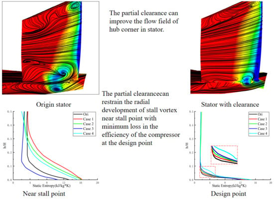
3.2. Control Method of the Clearance of the Stator

The effect of clearance leakage on the stall of compressor blades with different flow coefficients is discussed earlier. For compressor stators, generally hub corner separation/stall is the main research content of the secondary flow. In this paper, a stall occurs in the stator of the compressor at a low flow coefficient. The partial stator clearance is used as a passive control method. A large number of scholars have done a detailed study on the formation mechanism of the stall and the development of hub corner separation. For different clearance schemes, the prototype stator which has the same boundary conditions as the near stall point is selected as the comparative study. The flow field of the hub corner at near stall point is shown in Figure 9. It can be seen from the figure that the baseline compressor stall occurs at the hub corner. The flow in the upper part of the stator is relatively good. The small spiral points are caused by the tip wake and there is no stall at the shroud corner.
There are closed separation regions in the lower half of the hub corner, corresponding to the three spiral points N 1, N 2, and N 3 (N means the node) in the figure. The hub surface layer forms the hub spiral point N 1 due to the large incidence at the blade root. The vortex core is located at 0.5 chord length, which corresponds to the high static entropy concentration region. The fluid on the pressure surface flows toward the trailing edge, goes back along the suction surface under the entrainment of N 1, and then rises to form the spiral point N 2. However, the scale is relatively small. At the same time, the small-scale spiral point N 2 induces the spiral point N 3. It can be said that N 1 is the main flow blockage in the flow field. The radial development of N 1 blocks the hub corner of the stator and causes aerodynamic instability. Therefore, the control of the hub corner stall should be based on increasing the axial momentum for the low energy of the hub boundary layer. After clearance is set at the root of the stator, the flow field near the stall point has changed.
In Figure 9b, the hub radial vortex interacts with the leakage flow generated by the clearance gap. The high momentum fluid produced by the leakage flow makes the radial vortex move towards the trailing edge. The radial vortex core moves from 0.5 chords to about 0.7 chords. At the same time, the radial vortex is unstable under the impact of leakage flow. After a part of the fluid is flushed to the trailing edge, two spiral points N 3 and N 4 connected by saddle point S 1 are formed at the trailing edge because of the lesser energy of the leakage flow. This is a closed separation formed by the typical saddle point spiral point, which has the nature of confinement. It can be seen from the entropy contour that the static entropy concentration region i.e., vortex core moves backward in comparison with the baseline flow field. However, the newly generated closed separation results in the expansion of the high entropy region and the increase of the root loss. At the same time, the clearance leakage is divided into two parts under the action of the radial vortex. One part is sucked by the unstable radial vortex system (N 1, N 3, N 4). The other part is thrown into the boundary layer of the suction surface of the blade under the rotating action of the vortex. It can be seen from the limit streamline of suction surface that the scale of concentrated shedding vortex on the suction surface is larger in comparison with the prototype because of the inflow of partial leakage flow. The radial scale of the concentrated vortex developed from 0.3 H to 0.5 H. Although the scale increases but the strength of the vortex weakens. It shows that the static pressure coefficient of the corner increases and the low-pressure area of the baseline decreases, which indicates the impact of the clearance leakage making the vortex into an unstable state.
It can be seen from the limit streamlines in Figure 9c that the leakage flow generated by the tail gap has stronger momentum and the radial vortex is broken under the impact of the leakage flow. An obvious impact path of leakage flow can be seen between the broken small vortices. The whole hub area is composed of several small vortices after crushing. The leakage flow induces a new spiral point at the leading edge of the stator. In the entropy contour, the high entropy concentration area of the hub disappears. The high loss area of the hub is smaller than that of the hub compared with Case 1. Due to the lack of low energy fluid transport from the boundary layer of the hub, the central vortex in the rear gap is unstable. The whole spiral structure in the clearance of the trailing edge is destroyed. In topology, it turns into an unstable structure with a spiral point and saddle point closely connected.
Case 3 has maximum leakage momentum in Figure 9d. The closed separation of the hub corner disappears completely, except for the spiral point N 1, which is induced by the leakage flow in the front of the clearance. There is no other closed separation in the stator. An open separation line L1 formed by clearance leakage is on the hub. At the same time, the effect of leakage restrains the formation of concentrated shedding vortex. The spiral point on the suction surface disappears. In Figure 9a,b,c, the large-scale entropy increasing region is replaced by the leakage vortex. The entropy increase of open separation is much smaller than that of closed separation. Thus, it can be said that this control method is effective.
On the hub surface, the radial vortices break into small vortices in Figure 9e, which is similar to Case 2. The difference is that Case 4 has more leakage momentum. The scale of the small vortex formed by Case 4 is smaller than that of the Case 2. At the same time, the forward movement of the leakage vortex makes the concentrated shedding vortex to regenerate. In the entropy contour diagram, it can be seen that there is a high entropy region at the front edge of the suction. This is formed by leakage flow and broken radial vortex.
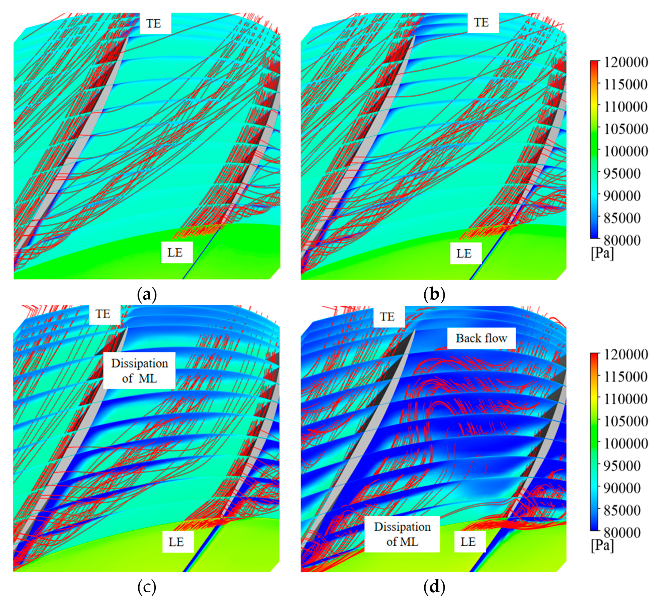
The law of vortex evolution can be obtained by comparing the streamline distribution of S 3 flow surface at the stator. Starting from 0.1 C flow surface, there are six S 3 flow surfaces selected to be studied. The flow field structure is shown in Figure 10. The radial scale of stall vortex and its development along chord can be clearly seen in S 3 flow surface. Figure 10a is the baseline stator. The node starting at 0.1 C marks the beginning of flow separation on the suction surface i.e., at the radial height 0.1 H. It is affected by the low energy fluid in the downstream of the corner. On the one hand, it is developing along the blade span. However, On the other hand, it moves to the pressure surface. At the same time under the action of the reverse pressure gradient, the node changes to the spiral point. At 0.5 C, it is transformed into a spiral point of completed closed separation, which corresponds to the vortex core region of stall vortex. There are obvious saddle points at 0.9 C. According to the topological rule, the spiral point and saddle point always appear in pairs, which can determine the nodes in the flow field to be transformed into spiral points. At the same time, it can be seen that the radial dimension of the stall region in the hub corner is about 0.4 H.
In Figure 10b, at 0.05 H, part of the fluid is sucked into the suction surface through the trailing edge clearance. There is obvious backflow on the surface of S 3, which starts at 0.9 C and ends at 0.5 C. Since the radial vortex is not changed by leakage, the node migration and transformation in Figure 10a still occur at the trailing edge clearance. The radial scale of the high entropy region is slightly larger than that of the baseline because the entrainment makes the concentrated vortex stronger, which is consistent with the previous literature. The radial height of the high entropy region decreases in Case 2 compared to Case 1 and the saddle point is pushed back from 0.5 C to 1.1C. At the same time, the leading-edge fluid is transported to the clearance leakage flow at 0.3 C. The high entropy area in the stator field is obviously reduced in case 3. At 0.5 C, the gap leakage vortex begins to form, the height of which does not exceed 0.05 H. It can be said that the Case 3 can effectively control the angular separation. The control effect of Case 4 is similar to that of Case 3. Both of them can reduce the radial scale of the high entropy region. The difference is that the vortex-induced by leakage in Case 4 is closer to the suction surface, as the leakage vortex with stronger momentum in case 3 will induce the vortex to blow to the pressure surface. It is worth mentioning that case 4 formed a sudden increase of static entropy after 0.7 C and 0.9 C. Case 4 worsens the flow field at the trailing edge. This is caused by the angle of blade curvature. In the same stator, the more distant the clearance position is, the incidence of the jet becomes larger relative to the trailing edge. It is more likely to cause flow separation, which further explains the reason why the front clearance can broaden the stall margin better but cause greater loss at the design point.
The three-dimensional interaction of radial flow and clearance leakage flow in hub corner stall is further discussed in Figure 11. The black streamline in the figure represents the radial vortex of the stall, and the yellow streamline represents the clearance leakage. In order to describe the existence of vortices, this paper selects the criterion of vortices i.e., Q criterion as the basis of identifying vortices. It is worth mentioning that the Q criterion proposed by Hunt et al. in 1988 is used as a criterion for vortex prediction. The value of the relative helicity is illustrated with variance in color. In this paper, Q = 50000 s−2. The interaction of vortices mentioned in the previous literature can be seen in Figure 11.
Figure 12 shows the reason why different clearance positions have different effects on the hub corner stall control. The main reason for corner separation/stall is that the low energy fluid in the boundary layer cannot resist the transverse pressure gradient in the flow passage and accumulate at the suction surface. With the decrease of the flow rate, the axial momentum of the low-energy fluid weakens. There will be backflow once the fluid cannot resist the reverse pressure gradient of the flow direction. The radial development of backflow forms the radial vortex of hub corner stall, which is like a tornado. The purpose of gap control technology is to strengthen the low-energy fluid in order to resist the transverse and reverse pressure gradient. Therefore, the difference in clearance control effect on different positions depends on the leakage momentum of clearance. The product of velocity and density of clearance leakage is defined as leakage momentum. In Figure 12, it can be seen that the leakage momentum increases gradually as the clearance moves forward and reaches its maximum in Case 3, and Case 4 has the least momentum. This explains the relationship between the clearance position and the control effect.
The radial parameter distribution of the stator is obtained by averaging the numerical simulation results in the circumferential direction as shown in Figure 13 and Figure 14. In order to further analyze the influence of the clearance on the compressor performance. Figure 13a shows the near stall point. It can be seen that Case 3 can effectively reduce the static entropy at the blade root. The static entropy is larger because the fluid of case 1 is drawn toward the suction surface. For Case 2 and Case 4, the leakage flow vortex breaks the radial stall vortex. Consequently, the static entropy caused by the broken vortex is higher than that of the baseline stator at a 30% blade span. From 30% to 50% blade span, the static entropy decreases. This shows that the clearance can effectively control the radial development of stall vortex. In addition to the control effect at the near stall point, the control effect at the design point is also very important in the passive control. In Figure 13b, it can be seen that all the clearance will increase the static entropy of the flow field under 10% blade height. However, except case 1, the rest cases have little effect on the static entropy at the blade root. This kind of local clearance control has the least damage to the design point in comparison with the uniform clearance.
The major effect of hub corner stall is that the stall fluid blocks the flow passage and reduces the flow capacity of the compressor. Therefore, this paper uses axial AVD to measure the flow capacity at the outlet. In addition to Case 4, other cases have little effect on AVD at the design point. At the near stall point, Case 3 can effectively increase AVD and the capacity of the flow passage. This is consistent with the previous static entropy contour in Figure 10. Thus, it is concluded that Case 3 can improve the hub corner stall near the stall point and has the least impact on the flow field performance at the design point.

3.3. Influence of Partial Clearance on Compressor Performance

At 0.6 N, the back pressure of the baseline compressor is gradually increased considering the complete convergence solution of each step as the initial field. The last convergent solution before divergence is taken as the near stall point. In this manner, the baseline compressor and the pressure ratio-efficiency characteristic lines under different clearances are obtained as shown in Figure 15.
Here, the efficiency means isentropic efficiency, which is defined as
η is * = π * k 1 k 1 θ * 1
where π * is total to total pressure ratio and θ * is total to total temperature ratio. k = 1.4 for air.
For different clearances, the blockage flow rate of the compressor is almost the same. However, the mass flow point at surge boundary moves to the left continuously as the clearance position of the stator partial clearance moves forward. Consequently, the stall margin is increasing. The formula used in this paper is
S M = ( π s * m s × m 0 π 0 * 1 ) × 100 %
The compressor margin is shown in Table 3. It can be seen that partial clearance can improve the stall margin of the compressor under lower operating conditions. However, the efficiency of the working point decreases rapidly as the position of the clearance moves toward the leading edge. It can be said that Case 3 obtains a higher margin with a reduction in the efficiency of the design point. Therefore, the performance of Case 3 is the best.

4. Discussion and Conclusions

The 1.5-stage axial compressor is numerically simulated. The stall mechanism and the effect of stator clearance at low operating conditions (0.6 N) are concluded as follows:
In this paper, the stalled mechanism of the compressor at low speed is not the breakdown or overflow of clearance leakage with the reduction inflow. The leakage flow in the main leakage area of the compressor gradually approaches the leading edge of the adjacent rotor. The dissipation position of the clearance leakage vortex moves forward gradually, under the action of the reverse pressure gradient. The secondary leakage area disappears. At the near stall point, the main flow at the top of the blade flows back, leading to a compressor stall.
The stator clearance is an effective passive control method for hub corner stall. The stall margin can be broadened at low speed in real compressors using this technique. The rotating stall of the compressor is caused by the deterioration of flow field at the tip of the rotor blade at low speed. There are two factors affecting the tip of the rotor at low speed, one is the tip clearance leakage vortex, the other is the radial vortex of the suction surface at the trailing edge. They interact at the rotor tip and block the flow path, which causes the rotating stall. However, the flow field of the stator will affect the compressor. The radial development of stall vortices in the corner is inhibited by the leakage flow generated in the partial clearance, and the flow field of the stator are improved, which affects the upstream rotor. The incidence of rotor root decreases. It keeps the radial vortex from moving to the rotor tip. Therefore, the compressor margin increases. At the same time, the reasonable choice of clearance position can restrain the radial development of stall vortex near stall point with minimum loss in the efficiency of the compressor at the design point.
The effect of different positions of clearance is different in the flow field control. As the position of clearance moves forward, the leakage flow caused by partial clearance increases until it reaches the maximum at the mid clearance. After mid-point, the further movement in the position of clearance decreases the leakage momentum. When the clearance is close to the vortex core of the separation vortex on the suction surface, the stall control effect is the best at the hub corner.

Author Contributions

Conceptualization, W.Z., Q.Z., B.J., and A.L.; Methodology, W.Z., Q.Z., and B.J.; Software, W.Z. and B.J.; Validation, W.Z. and B.J.; Formal analysis, W.Z., Q.Z., and B.J.; Investigation, W.Z.; Writing—original draft preparation, W.Z.; Writing—review and editing, W.Z., Q.Z., B.J., and A.L.; Supervision, Q.Z. and B.J.; Funding acquisition, Q.Z. and B.J. All authors have read and agreed to the published version of the manuscript.

Funding

This research was funded by the National Major Science and Technology Project, grant number 2017-II-0006-0019; 2017-I-0009-0010.

Conflicts of Interest

The authors declare no conflict of interest.

Abbreviations

MLMain Leakage
SLSecondary Leakage
RVRadial Vortex
CpPressure coefficient
LVLeakage Vortex
AVDAverage Velocity Density
SSSuction Side
PSPressure Side
LELeading Edge
TETrailing Edge
NNode
CChord Length

References

  1. Jiang, B.; Shi, X.; Zheng, Q.; Zhu, Q.; Chen, Z.; Tian, Z. The Relationship of Spike Stall and Hub Corner Separation in Axial Compressor. Int. J. Turbo Jet-Engines 2017, 37, 1–16. [Google Scholar] [CrossRef]
  2. Hoying, D.A. Stall inception in a multi-stage high speed axial compressor. In Proceedings of the 29th Joint Propulsion Conference and Exhibit, Monterey, CA, USA, 28–30 June 1993. [Google Scholar]
  3. Suder, K.L.; Celestina, M.L. Experimental and Computational Investigation of the Tip Clearance Flow in a Transonic Axial Compressor Rotor. Asme J. Turbomach. 1996, 118, 218–229. [Google Scholar] [CrossRef] [Green Version]
  4. Lin, A.; Sun, Y.; Zhang, H.; Lin, X.; Yang, L.; Zheng, Q. Fluctuating characteristics of air-mist mixture flow with conjugate wall-film motion in a compressor of gas turbine. Appl. Therm. Eng. 2018, 142, 779–792. [Google Scholar] [CrossRef]
  5. Hah, C. A Numerical Modeling of Endwall and Tip-Clearance Flow of an Isolated Compressor Rotor. J. Eng. Gas Turbines Power 1986, 108, 15. [Google Scholar] [CrossRef]
  6. Hewkin-Smith, M.; Pullan, G.; Grimshaw, S.D.; Greitzer, E.M.; Spakovszky, Z.S. The role of tip leakage flow in spike-type rotating stall inception. J. Turbomach. 2019, 141, 061010. [Google Scholar] [CrossRef] [Green Version]
  7. Smith, G.D.J.; Cumpsty, N.A. Flow Phenomena in Compressor Casing Treatment. J. Eng. Gas Turbines Power 1982, 106, 532–541. [Google Scholar] [CrossRef]
  8. Chen, H.; Huang, X.; Fu, S. CFD Investigation on Stall Mechanisms and Casing Treatment of a Transonic Compressor. In Proceedings of the 42nd AIAA/ASME/SAE/ASEE Joint Propulsion Conference & Exhibit, Sacramento, CA, US, 9–12 July 2006. [Google Scholar]
  9. Crook, A.J.; Greitzer, E.M.; Tan, C.S. Numerical simulation of compressor endwall and casing treatment flow phenomena. Asme J. Turbomach. 1990, 112, 868–894. [Google Scholar]
  10. Joslyn, D.H.; Dring, R.P. Axial Compressor Stator Aerodynamics. ASME J. Eng. Gas Turbines Power 1985, 107, 485–493. [Google Scholar] [CrossRef]
  11. Friedrichs, J.; Baumgarten, S.; Kosyna, G.; Stark, U. Effect of stator design on stator boundary layer flow in a highly loaded single-stage axial-flow low-speed compressor. In Proceedings of the ASME Turbo Expo 2000: Power for Land, Sea, and Air, Munich, Germany, 8–11 May 2000. ASME Paper, 2000-GT-616. [Google Scholar]
  12. Gannon, A.J.; Hobson, G.V.; Shreeve, R.P.; Villescas, I.J. Experimental investigation during stall and surge in a transonic fan stage & rotor-only configuration. In Proceedings of the ASME Turbo Expo 2006: Power for Land, Sea, and Air, Barcelona, Spain, 8–11 May 2006. ASME Paper, GT2006-90925. [Google Scholar]
  13. Thiam, A.H.; Whittlesey, R.W.; Wark, C.E.; Williams, D.R. Corner Separation and the onset of stall in an axial compressor. In Proceedings of the 60th Annual Meeting of the Divison of Fluid Dynamics, Salt Lake City, UT, USA, 18 November 2007. [Google Scholar]
  14. Berdanier, R.A. Design of a Multi-Stage Research Compressor for Cantilevered Stator Hub Clearance Flow Investigations. Master’s Thesis, Purdue University, West Lafayette, IN, USA, 2012. [Google Scholar]
  15. Gbadebo, S.A.; Cumpsty, N.A.; Hynes, T.P. Three-Dimensional Separations in Axial Compressors. J. Turbomach. 2005, 127, 331–339. [Google Scholar] [CrossRef]
  16. Hanan, L.; Qiushi, L. Cantilevered stator hub leakage flow control and loss reduction using non-uniform clearances. Aerosp. Sci. Technol. 2016, 51, 1–10. [Google Scholar] [CrossRef]
  17. Zhao, W.; Jiang, B.; Duan, Y.; Tian, Z.; Zheng, Q. Volume 2A: Turbomachinery—The Mechanism of the Flow in the Hub Corner and the Control by Tailing Edge Gaps. In Proceedings of the ASME Turbo Expo 2018: Turbomachinery Technical Conference and Exposition, Oslo, Norway, 11 June 2018. [Google Scholar]
  18. Zhao, W.; Jiang, B.; Zheng, Q. Control of the Corner Separation in a Linear Cascade by Trailing Gaps. In Proceedings of the Asme Turbo Expo: Turbomachinery Technical Conference & Exposition, Charlotte, NC, USA, 26–30 June 2017. [Google Scholar]
  19. Akcayoz, E.; Duc Vo, H.; Mahallati, A. Controlling Corner Stall Separation With Plasma Actuators in a Compressor Cascade. J. Turbomach. 2015, 138. [Google Scholar]
  20. Chen, P.P.; Qiao, W.Y.; Liesner, K.; Meyer, R. Effect of Segment Endwall Boundary Layer Suction on Compressor 3D Corner Separation. In Proceedings of the ASME Turbo Expo 2015: Turbine Technical Conference and Exposition, Montreal, QC, Canada, 15–19 June 2015. [Google Scholar]
  21. Gbadebo, S.A.; Cumpsty, N.A.; Hynes, T.P. Control of Three-Dimensional Separations in Axial Compressors by Tailored Boundary Layer Suction. J. Turbomach. 2008, 130, 30–37. [Google Scholar] [CrossRef]
  22. Jia, X.; Zhang, H.; Zheng, Q. Numerical investigation on the effect of hot running rim seal clearance on hot gas ingestion into rotor-stator system. Appl. Therm. Eng. 2019, 152, 79–91. [Google Scholar] [CrossRef]
  23. Kiesner, M.; King, R. Volume 2A: Turbomachinery—Closed-Loop Active Flow Control of the Wake of a Compressor Blade by Trailing-Edge Blowing. In Proceedings of the ASME Turbo Expo 2015: Turbine Technical Conference and Exposition, Montreal, QC, Canada, 15 June 2015. [Google Scholar]
  24. Marciniak, V.; Longhitano, M.; Kügeler, E. Assessment of Transition Modeling for the Design of Controlled Diffusion Airfoil Compressor Cascades. In Proceedings of the ASME Turbo Expo 2013: Turbine Technical Conference and Exposition, San Antonio, TX, USA, 3–7 June 2013; American Society of Mechanical Engineers: New York, NY, USA, 2013. V06AT35A016-V06AT35A016. [Google Scholar]
  25. Lin, A.; Zheng, Q.; Jiang, Y.; Lin, X.; Zhang, H. Sensitivity of air/mist non-equilibrium phase transition cooling to transient characteristics in a compressor of gas turbine. Int. J. Heat Mass Tran. 2019, 137, 882–894. [Google Scholar] [CrossRef]
  26. Lin, A.; Zheng, Q.; Fawzy, H.; Luo, M.; Zhou, J.; Zhang, H. Effect of water injection cooling on flow field characteristics in the cooling section of precooled turbine-based combined cycle engine. Int. J. Heat Mass Tran. 2019, 141, 615–626. [Google Scholar] [CrossRef]
  27. Reid, L.; Moore, R.D. Design and Overall Performance of Four Highly Loaded, High Speed Inlet Stages for an Advanced High-Pressure-Ratio Core Compressor; NASA-TP-1337; National Technical Information Service: Springfield, VA, USA, 1978; pp. 6–10.
  28. Lin, A.; Zhou, J.; Fawzy, H.; Zhang, H.; Zheng, Q. Evaluation of mass injection cooling on flow and heat transfer characteristics for high-temperature inlet air in a MIPCC engine. Int. J. Heat Mass Tran. 2019, 135, 620–630. [Google Scholar] [CrossRef]
  29. Han, X.; Zeng, W.; Han, Z. Investigating the dehumidification characteristics of the low-pressure stage with blade surface heating. Appl. Therm. Eng. 2020, 164, 114538. [Google Scholar] [CrossRef]
  30. Jiang, X.; Lin, A.; Ma, H.; Li, X.; Li, Y. Minimizing the thermal bridge through the columns in a refrigeration room. Appl. Therm. Eng. 2020, 165, 114565. [Google Scholar] [CrossRef]
Figure 1. (a) Computational domain; (b) computational mesh of 1.5-stage compressor; (c) validation of grid independence-mass flow; (d) validation of grid independence efficiency.
Energies 13 02691 g001
Figure 2. Partial clearance schemes for (a): Case 1, (b): Case 2, (c): Case 3, and (d) Case 4.
Energies 13 02691 g002
Figure 3. Comparison between numerical calculations and experimental results. (a) The distribution of pitch-averaged efficiency of the ROTOR 37 in the 0.98 chocking mass condition; (b) the distribution of pitch-averaged pressure ratio of the ROTOR 37 in the 0.98 chocking mass condition.
Energies 13 02691 g003
Figure 4. Relative total pressure contour at the rotor outlet section. (a) operation point 1 (OP1); (b) OP2; (c) position of OP1 and OP2.
Energies 13 02691 g004
Figure 5. Static pressure contour/limiting streamlines. (a) OP1; (b) OP2.
Energies 13 02691 g005
Figure 6. Vorticity contour at 0.98 H of rotor with different flow coefficient. (a) 0.5; (b) 0.46; (c) 0.42; (d) 0.36.
Energies 13 02691 g006
Figure 7. Leakage structure in the tip of the rotor. (a) 0.5, (b) 0.46, (c) 0.42, (d) 0.36.
Energies 13 02691 g007
Figure 8. Static pressure and AVD. (a) Static pressure coefficient at 0.99 H; (b) AVD at the outlet of the rotor.
Energies 13 02691 g008
Figure 9. Static pressure contour/limiting streamlines and entropy contour at 0.05 H for (a) Ori, (b) Case 1, (c) Case 2, (d) Case 3, and (e) Case 4.
Energies 13 02691 g009aEnergies 13 02691 g009b
Figure 10. Entropy contour and surface streamlines. (a) Ori; (b) Case 1; (c) Case 2; (d) Case 3; (e) Case 4.
Energies 13 02691 g010
Figure 11. Three-dimensional clearance leakage and the radial streamlines (Q = 50,000 s−2). (a) Case 1; (b) Case 2; (c) Case 3; (d) Case 4.
Energies 13 02691 g011
Figure 12. Momentum of the leakage flow.
Energies 13 02691 g012
Figure 13. Radial distribution of static entropy for (a) OP2 and (b) OP1.
Energies 13 02691 g013
Figure 14. Radial distribution of AVD for (a) OP1 and (b) OP2.
Energies 13 02691 g014
Figure 15. Characteristic lines with different clearances. (a) Efficiency; (b) total pressure ratio.
Energies 13 02691 g015
Table 1. Parameters of design-point of the 1.5 stages at 0.6 N.
Isentropic EfficiencyPressure RatioMass Flow (kg/s)
0.9331.11460.6
Table 2. Clearance parameters in different cases.
Case 1Case 2Case 3Case 4
Length (l/C)0.50.50.50.5
Length (m)0.0650.0650.0650.065
Height (h/H)0.4%0.4%0.4%0.4%
Height (mm)1111
PositionsTrailing edgeBackMiddleFront
Table 3. The compressor surge margin for all the cases.
ORICASE 1CASE 2CASE 3CASE 4
Margin25.4%26.6%28.3%30%34.4%

