Article

Potential Sites for Underground Energy and CO2 Storage in Greece: A Geological and Petrological Approach

by
Apostolos Arvanitis
1,
Petros Koutsovitis
2,*,
Nikolaos Koukouzas
3,
Pavlos Tyrologou
3,
Dimitris Karapanos
3,
Christos Karkalis
3,4 and
Panagiotis Pomonis
4
1
Hellenic Survey of Geology and Mineral Exploration (HSGME), 13677 Attica, Greece
2
Section of Earth Materials, Department of Geology, University of Patras, GR-265 00 Patras, Greece
3
Centre for Research and Technology, Hellas (CERTH), 15125 Marousi, Greece
4
Department of Mineralogy and Petrology, Faculty of Geology and Geoenvironment, National and Kapodistrian University of Athens, Zografou, P.C. 15784 Athens, Greece
*
Author to whom correspondence should be addressed.
Energies 2020, 13(11), 2707; https://doi.org/10.3390/en13112707
Submission received: 9 April 2020 / Revised: 22 May 2020 / Accepted: 25 May 2020 / Published: 28 May 2020
(This article belongs to the Special Issue Solid Fuels Technology and Applications.)

Abstract

:
Underground geological energy and CO2 storage contribute to mitigation of anthropogenic greenhouse-gas emissions and climate change effects. The present study aims to present specific underground energy and CO2 storage sites in Greece. Thermal capacity calculations from twenty-two studied aquifers (4 × 10⁻⁴–25 × 10−3 MJ) indicate that those of Mesohellenic Trough (Northwest Greece), Western Thessaloniki basin and Botsara flysch (Northwestern Greece) exhibit the best performance. Heat capacity was investigated in fourteen aquifers (throughout North and South Greece) and three abandoned mines of Central Greece. Results indicate that aquifers present higher average total heat energy values (up to ~6.05 × 10⁶ MWh(th)), whereas abandoned mines present significantly higher average area heat energy contents (up to ~5.44 × 10⁶ MWh(th)). Estimations indicate that the Sappes, Serres and Komotini aquifers could cover the space heating energy consumption of East Macedonia-Thrace region. Underground gas storage was investigated in eight aquifers, four gas fields and three evaporite sites. Results indicate that Prinos and South Kavala gas fields (North Greece) could cover the electricity needs of households in East Macedonia and Thrace regions. Hydrogen storage capacity of Corfu and Kefalonia islands is 53,200 MWh(e). These values could cover the electricity needs of 6770 households in the Ionian islands. Petrographical and mineralogical studies of sandstone samples from the Mesohellenic Trough and Volos basalts (Central Greece) indicate that they could serve as potential sites for CO2 storage.

1. Introduction

The use of fossil fuels as energy sources is one of the major contributors of anthropogenic greenhouse gas emissions that include CO2 [1,2,3]. To mitigate the effects of global warming the implementation of CO2 Capture and Storage (CCS) practices is considered as a state-of-the-art technology that aims to reduce emissions of CO2 into our living atmosphere [4]. To achieve efficient and sustainable energy management it is important to promote practices that aim to reduce the carbon footprint through utilisation of renewable energy resources (wind, biomass, solar and geothermal energy) in Greece with integration of energy storage concepts [5]. This can be achieved with gradual transition to eco-friendly energy systems that promote energy production with the inclusion of Renewable Energy Sources utilisation. This energy transition presents significant and important developments, such as the geothermal energy exploitation in Kenya [6]. However, their global contribution in total renewable energy production is small. This is attributed to the obvious difficulties that are linked with the supply of renewable sources. In the current stage, even more countries tend to adapt and promote the use and research on renewable energy sources [7].
More specifically, energy storage applications as a concept aim to provide technologies that convert energy into storable forms [8]. It also balances energy consumption with production by storing excess energy for long and/or short periods [9]. Despite the cover of energy demands (i.e., seasonal, daily), energy storage provides additional benefits such as: decrease of operational costs, integration of variable energy sources (such as wind, solar, natural gas and geothermal energy) and reduction of environmental effects (low carbon energy supply). Supplementary energy conversion processes are often required, depending on the source type and the implemented storage technology. Energy storage systems can be distinguished into mechanical, chemical, biological, magnetic, thermal and thermochemical types [10]. The choice of the appropriate storage technology depends on the storage purpose, the type of energy source the available storage capacity cost, lifetime and environmental impact [8]. Energy storage systems are distinguished into ground (ground-based ex-situ) and underground (geological in-situ) types. Underground energy storage requires suitable geological reservoirs such as: depleted hydrocarbon reservoirs, rock bodies with appropriate lithotypes (ultramafic rocks, basalts and sandstones), deep saline aquifers, salt caverns and abandoned mines.
Underground Thermal energy storage systems (UTES) provide the opportunity to store thermal energy, by utilising the heat capacity of underground soil and/or rock volumes [11]. To date, the best-established types of seasonal UTES systems [12,13] are aquifer storage (ATES), borehole storage (BTES), cavern storage (CTES), pit storage (PTES) and seasonal tank storage (TTES). There are many specific localities with potential for underground energy storage in Greece [14]. Aquifers for seasonal underground heat or natural gas storage are in sedimentary basins of the Greek mainland (such as Thessaloniki basin; North Greece), as well as in the Aegean islands (such as Evia, Lesvos, Chios and Rhodes). Natural gas can be sufficiently stored in depleted natural gas reservoirs that exist in Greece (Figure 1), which are selected on the basis of a sufficiently large volume of pore space, preferably high permeability of reservoir rocks and the absence of gas admixtures such as hydrogen sulphides. Hydrocarbon reservoirs that could serve as potential sites for underground gas storage include those of Epanomi (Thessaloniki, North Greece), Katakolo (South Greece) and Prinos (North Greece) [14].
Apart from the aforementioned, hydrogen is considered nowadays as an important key source for clean, secure and affordable energy, since it can improve efficiency of power systems and reduce environmental impact of power production [15]. Hydrogen can be stored into porous reservoir rocks such as depleted natural gas or petroleum deposits [16] and salt caverns [16,17]. In Greece, the most suitable formations for considering hydrogen storage (Figure 1) are the caverns in salt/evaporite formations due to the fact that they allow higher injection and withdrawal rates compared to other means of storage [18] thus resulting in high energy deliverability to the energy grid. Evaporite formations of Heraklion (Crete Island; South Aegean) are suitable for underground gas storage, whereas Corfu and Kefallonia Islands (Ionian Sea) could serve as sites for underground hydrogen storage. The abandoned mines of Mandra and Chaidari regions (Attica; Central Greece), as well as the Aliveri mine (Evia Island; Central Greece) could be exploited for underground heat storage purposes.
Several research studies have developed effective methods for carbon capture, by utilising technologies such as membranes, adsorption-based separation of CO2 [20]. There are many options for Geological CO2 storage such as deep saline formations [21], abandoned coal mines [22], salt caverns [23], coal seams [24] and depleted hydrocarbon fields [25]. In many cases, CO2 storage can be combined with extraction of crude oil (CO2-Enhacned Oil Recovery [26]) or natural gas from hydrocarbon reservoirs (CO2-Enhanced Gas Recovery). Mineralisation is an alternative option of CO2 sequestration. Several rock types have been considered as potential underground reservoirs for mineral storage of carbon, or to withhold for a relatively short period of time specific amounts of CO2. These include: (a) basalts with high porosity, silica undersaturated nature, abundance of plagioclase and feldspars and low alteration grade (recent age) [3,27,28], (b) sandstones [29,30] and (c) serpentinite bodies [31,32].
The most common parameters that must be considered prior to the implementation of CO2 storage in the aforementioned formations include, the storage capacity, porosity and permeability of the reservoir rock. In addition, the possibility of CO2 leakage or defects associated with cement degradation must be examined prior to CO2 storage in cases of depleted hydrocarbon reservoirs [33]. The possibility of migration of the injected CO2 and/or brine into the drinking water zones is a major concern that must be taken into account in the case of deep saline aquifers [21].The absence of lateral communication with other mines and/or with the surface (to avoid gas leakage), as well as the minimum depth of the mine top are crucial parameters for CO2 storage in abandoned coal mines [34]. Regarding the CO2-mineralisation in rocks, the abundance of Ca–Fe–Mg bearing minerals significantly affects the amount of carbonate minerals produced during reaction of the rock with the injected CO2 [3].
At the current stage Greece has not developed and adopt significant CO2 storage sites and policies, while there are only few studies concerning the application of Carbon Capture and Storage (CCS) technologies in this region [35]. In Greece, the regions of Volos (Figure 1) [3], the Mesohellenic Trough [29], the Prinos oil and gas field (Kavala; North Greece) and also parts of Western Greece [36] encompass the appropriate rock types that could serve as potential sites for CO2 storage. Preliminary estimations of CO2 storage in Volos basalts indicate storage capacity of ~43,200 tons CO2 at 300 m depth [3]. Calculations conducted by [37] present high storage capacity of CO2 in the Pentalofos and Eptachori sedimentary formations of the Mesohellenic Trough at 2 and 3 km depths, respectively. Calculations of CO2 storage at Klepa-Nafpaktia sandstones in Western Greece indicate storage capacity of 18 × 105 tons of CO2 at 500 m depth [36]. Additional study indicates that ultramafic rocks from Vourinos ophiolite complex (Western Macedonia; North Greece) could be used for CO2 sequestration purposes [38].
The present study aims to present, map and investigate specific underground energy storage sites that can be considered to potentially utilise Underground Thermal Energy Storage (UTES), Underground Gas Storage (UGS), Hydrogen and CO2 underground storage practices in Greece. For this purpose, we considered data derived from petrological and geochemical assessments, field observations and referenced data from extensive literature review, but also through the application of energy storage calculations that take into consideration the physicochemical properties of the potential reservoirs. In this framework, we aim to revise and upgrade preliminary research results provided by [39].

2. Analytical Techniques

Preliminary results of the selective surface rock samples from several parts of the Mesohellenic Trough and the region of Volos have been examined regarding their petrographic properties. Four sandstone samples were collected from the regions between Deskati and Doxiana near Grevena and one sandstone sample was collected from the Lignite Center of Western Macedonia near Ptolemais. Three basaltic rock samples were examined from the regions of Microthives and Porphyrio near Volos. XRD analyses were conducted at CERTH’s (Centre for Research and Technology, Hellas) Laboratories, using a Philips X’Pert Panalytical X-ray diffractometer (Malvern Panalytical, Malvern, UK) that operates with Cu radiation at 40 kV, 30 mA, 0.020 step size and 1.0 s step time. Interpretation of XRD results, was accomplished by deploying the DIFFRAC.EVA software v.11 (Bruker, MA, USA), which is based on the ICDD (International Center for Diffraction Data) Powder Diffraction File (2006). Sandstone and basaltic rock samples were examined through petrographic observations in polished thin sections using a Zeiss Axioskop-40 (Zeiss, Oberkochen, Germany), equipped with a Jenoptik ProgRes CF Scan microscope camera at the Laboratories of CERTH. The modal composition of pores was calculated based upon ~1000-point counts on each thin section. Quantification of modal composition was accomplished by using microphotography of SEM images at CERTH’s Laboratories with a SEM–EDS (Scanning Electron Microscopy with Energy Dispersive Spectroscopy) JEOL JSM-5600 scanning electron microscope (Jeol, Tokyo, Japan), equipped with an automated energy dispersive analysis system Link Analytical L300 (Oxford Instruments, Abington, UK), with the following operating conditions: 20 kV accelerating voltage, 0.5 nA beam current, 20 s time of measurement, and 5 µm beam diameter. The petrographic description of the sandstone and basaltic rock samples coupled with data provided by extensive literature review are presented below.

3. Geological Background and Petrological Investigation of Rock Types Considered for Storage

3.1. Evaporite Formations

In the Ionian and Pre-Apulian geotectonic zones, evaporites exhibit Triassic and Triassic–Lower Jurassic ages, respectively. The thrust boundary between the Ionian and pre-Apulian zones is marked by intrusion of evaporite occurrences, mostly after the effects of diapirism [40,41]. In the regions of Epirus and Akarnania (Western Greece), Triassic evaporites occur in various localities and in the central part of the Corfu Island [42]. These occurrences provide proof that in the External Hellenides the evaporites represent the lowest detachment level of individual overthrust sheets [43]. Their thickness varies but in most cases is about 2–3 km, although locally it can reach up to 4 km [44,45,46]. Diapiric forms are usually observed in local scale, resulting in the deformation of the adjacent sedimentary rocks including those of Zavrohon diapir, that has also been confirmed by drilling boreholes [44]. Evaporite formations from Agios Sostis and Laganas regions in Zakynthos island (Western Greece) are represented by the Messinian evaporite unit [47]. These formations consist of nodular and banded evaporate minerals often being in contact with turbidite successions, whereas their formation is associated with present-day active tectonics [44,47].
The principal evaporite mineral phases that have been identified in the Greek evaporite formations are gypsum, halite and anhydrite [40,48]. On their upper stratigraphic levels, dolomite occasionally participates in the form of breccias, which is mostly observed in the Triassic formations. Accessory mineral phases include bassanite and celestite that are not always present. In Northwestern Greece, the porosity of evaporitic formations ranges widely from relatively impermeable to very permeable attributed to local karstification processes [49].
Triassic evaporites from the regions of Anthoussa and Agios Ioannis (West Greece) [50] indicate that these can be distinguished into two main types (Type-23 and Type-24) of Standard Microfacies based on the Flugel classification [51]. Both types are rich in dolomite and solution collapse breccia, whereas calcite, gypsum and anhydrite appear in notable but lower amounts [50]. Type-23 evaporites are laminated by layers of gypsum, anhydrite and dolomite. Dolomite ranges between 40%–60%, evaporite crystals are often calcified and form lenses and rosettes within the mudstone groundmass, whereas relic sparite and evaporite minerals are also observed [50]. Their secondary porosity ranges between 20%–30%. Type-24 evaporites are classified as dolomites and dolomitic limestones. Their depositional texture corresponds to mudstone-grainstone types [50]. Micritic cement is highly but not totally dolomitised, whereas sparitic material usually occurs as cementitious material [50]. Dolomite is present in high amounts reaching 80% [50]. Evaporite minerals reach ~20% and usually form rosette and lenses within the groundmass [50]. Secondary porosity ranges between 15%–40% [50].
Evaporite samples studied from different drilling depths at the region of Kristallopigi (Igoumenitsa; Western Greece) [49] include claystones and siltstones in the upper parts and organic rich evaporites with claystone intercalations in the lower parts. Their mineralogical composition is distinguished into evaporitic and non-evaporitic, including the following assemblages gypsum–anhydriten–bassanite–celestite and quartz–feldspar–calcite–dolomite–magnesite clays, respectively [49]. Clay minerals are classified as kaolinite, illite, smectite and mixed phases [49]. Regarding the evaporitic minerals gypsum is stressed and deformed presenting topotactic relation with bassanite crystals [49]. Bassanite is isolated or forms aggregates, whereas celestite is sub-idiotropic to tabular or prismatic forming aggregates or isolated crystals [49]. Porosity measurements show high variation between 0.31%–52.98% for the studied samples [49].

3.2. Sedimentary Basins

The Eocene-Miocene Mesohellenic Trough is an elongated sedimentary basin of 200 km length and 30–40 km width, located in NW Greece [52,53] between the Apulian (non-metamorphic) and the Pelagonian (metamorphic) microcontinental plates [54]. It is a back-arc sedimentary basin evolved during the Upper Oligocene to Miocene period [52,55,56,57], being superimposed on the Olonos-Pindos external and Pelagonian internal geotectonic units. It is the largest and most important molassic basin formed during the last Alpine orogenic stage of the Hellenides, which occurred between the Mid-Upper Eocene and the Mid-Upper Miocene, extending from Albania in the Northern parts, towards the Thessaly region in Greece at the South. The Mesohellenic Trough comprises of the following four main formations from downwards to surface: Eptachorio, Pentalofo, Tsotillio and Burdigalian [58]. The base of the Eptachorio Formation consists of clastic Upper Eocene to Lower Oligocene sediments (conglomerates, sandstones), as well as base deposits. The upper part of Eptachorio Formation (Figure 2a,b) is located in Taliaros Mountain (Grevena-Kastoria; West Macedonia) and appears in the form of local sedimentary phases comprising of sandstones, marls and limestones. The sequence presents thickness varying from 1000 to 1500 m. The Upper Oligocene to Lower Miocene Pentalofos Formation (Figure 2a,b) includes two types of clastic sedimentary rocks separated by marl–sandstone intercalations. Their thickness ranges from 2250 to 4000 m. The Tsotillio Formation (Lower to Middle Miocene) consists of marls accompanied by conglomerates, sandstones and limestones of variable thickness (200 to 1000 m). The Burdigalian Formation comprises of various phases of sediments such as sandy and silty marls, sand clays, sandstones, conglomerates and limestones [37,52,54]. These sediments are deposited in the form of sedimentary wedges. The aforementioned formations are covered from: (a) Upper Eocene to Middle Miocene alluvial, lacustrine and terrestrial sediments and (b) Pliocene to Lower Pleistocene, fluvial and lacustrine clays, sands and loose conglomerates hosting lignite horizons, which in cases were deposited locally in the Mesohellenic Trough.
The widespread distribution of Mesohellenic Trough sandstones is usually favoured by their high permeability and geochemical characteristics that provide the potential for long-term pH buffer capacity [59]. High volume sandstones are deformed in open anticline structures representing possible porous reservoir rocks [60]. Sedimentary basins of comparable geological features including the Mesohellenic Trough were considered (Table 1) in the current study. In this frame, all of the other sights examined include a suitable geological reservoir consisting of sandstones that are overlain by Tsotyli formation) caprock [61]. Preliminary investigations were conducted in these sights combined with fieldwork and referenced data provided from the literature. These results showed that all the sandstone formations exhibit comparable textural and mineralogical features, presenting restricted variations in terms of porosity.
Their texture ranges from fine grained to medium grained, displaying variable amounts of sub-angular to sub-rounded lithic fragments and straight to suture grain contacts. It also ranges from poor to moderate sorted presenting high amounts of siliceous cement and local patches of calcareous cement material. Their mineralogical assemblage is composed mainly by quartz, alkali-feldspars, calcite (Figure 3), lithic fragments, mica (mostly muscovite and less frequently biotite) and chlorite (Figure 4c,d). Fragments are mostly composed by quartz and feldspar, as well as by clasts of magmatic origin. Quartz appears in the form of monocrystalline angular or polycrystalline sub-angular to sub-round grains. Quartz contacts are straight, suture or interlocking. K-feldspar occurs in the form of variable sized euhedral to subhedral crystals affected from different weathering degrees. Mica and chlorite appear within the sandstone matrix in the form of scarce occurrences developed intergranular between quartz and feldspar crystals.

3.3. Pleistocene Alkaline Basalt Occurrences

In Greece, these types of rocks are mostly of Triassic age, having been formed at the stage of oceanic rifting. Localities of these basaltic occurrences include Pindos (NW Greece) [62], Koziakas [63], Othris [64], Argolis [65], the South Aegean [66,67,68], Volos [3] and Evia Island [69]. Alkaline basalt occurrences of relatively recent age (Pleistocene) appear only in the form of scattered outcrops mostly in the Aegean Sea (Central Greece). These occurrences outcrop between North Evoikos and Pagasitikos gulfs (Central Greece) and were formed during Pleistocene by extensional back-arc processes associated with the activity of Northern Anatolia Fault [70,71,72]. These rocks crop out in the islands of Achilleio, Lichades and Agios Ioannis and consist of massive lavas and pyroclastic rocks [3]. In addition, extensional related basaltic rocks also crop out in the regions of Volos, Kamena Vourla and Psathoura (Central Greece) and they are classified as basaltic trachyandesites and trachyandesites [3]. The aforementioned rock types can serve as potential sites for applications of CO2 storage, which is further enhanced by their relatively low alteration grade. These volcanic centers are not genetically associated with those developed in the South Aegean arc, which resulted from the subduction of the African plate beneath the Eurasia [3,73,74].
Basaltic rocks from the region of Volos present fine grained holocrystalline trachytic or aphanitic groundmass, characterised from porphyritic vesicular textures (Figure 4a,b) Their mineralogial assemblage is composed mainly by subhedral to euhedral clinopyroxene and olivine phenocrystals (Figure 4a,b). Their groundmass is predominantly composed by needle to lath shaped plagioclase and clinopyroxene crystals (~60%). Accessory minerals include orthopyroxene, alkali-feldspar, amphibole, calcite within gas vesicles, pyrite and opaque oxide minerals such as ilmenite and magnetite.
Clinopyroxene is classified mainly as diopside presenting quite high FeO (FeO: 5.37–8.17 wt.%) and variable TiO2 and Al2O3 contents [3]. Olivine is classified as forsterite presenting higher MgO contents compared to those of FeO, whereas Mg# ranges highly [3]. Plagioclase of the basaltic groundmass is CaO rich classified as bytownite or labradorite, whereas the glassy part is characterised by high SiO2 and Al2O3 and total alkali (Na2O + K2O) contents [3].
The vast majority of basaltic samples present porosity within the range of 15%–23% corresponding to 18% average porosity of the studied suite [3]. Their porosity is highly affected from the occurrence of gas vesicles that present variable size range and are usually filled with secondary calcite.

4. Types of Energy and CO2 Storage Considered

4.1. Underground Thermal Energy Storage (UTES)

4.1.1. Thermal Capacity Properties of Aquifers

The Aquifer Thermal Energy Storage (ATES) is an open loop system that uses permeable water rock layers as means for storing thermal energy and water. Energy can be transferred into or extracted from aquifers using one or more injection and production wells connected with hydraulic pumps and heat exchangers [75]. This technology also can be combined with Geothermal Heat Pumps (GHP). ATES presents the highest energy efficiency compared to other geothermal technologies but strongly depends on the physical properties of the aquifer (thickness, heat capacity). It is also favourable for large-scale energy storage, such as seasonal storage.
In cases where they are overlain by impermeable sedimentary cap rocks (such as siltstones and shales), aquifers can serve as appropriate formations for thermal storage purposes due to their high porosity. In the current study twenty-two geological formations that present the necessary geological, petrological, mineralogical and textural features have been considered for implementation of underground thermal energy storage (Table 1). Thermal capacity, productivity and heat in place are parameters strongly associated with the pore volume and the physicochemical properties of an aquifer media (Table 1). Thermal energy capacity calculations in the studied aquifers was based on the following equation [76] (see Appendix A Table A1):
q = (Cp · rho)rock · (1 − φ) + (Cp · rho)water · φ
Based on referenced data specifications [76] a heat capacity value of 0.19 m (mineral matrix) and an average density of 1.41 kg/m3 were considered as appropriate values for the sandstone aquifers. Results of the current research study indicate that porosity ranges from 8% to 22%, with an average value of 14%. Therefore, the specific thermal capacity per cubic meter for the aquifers considered in the current study is calculated as follows: q = 2.36 × 10⁻⁵ MJ/m3·°C.
The parameters that have been taken into consideration in order to make our energy storage calculations are transmissivity (Table 2), productivity, porosity, aquifer thickness and permeability. In particular, transmissivity is the product of the aquifer thickness (D) and the average value of hydraulic conductivity (K). It is expressed in m2/day of aquifer thickness [77]. Transmissivity describes an aquifer’s capacity to transmit water.
T = K · D
The productivity of an aquifer depends on its ability to store and transmit water, as well as on the physicochemical characteristics of the geological formation [78]. Productivity is significantly associated with the porosity type, which is classified into primary and secondary [78,79]. In the first case, water is stored within the interstices between grains, whereas secondary porosity refers to the water stored and/or flowing through fractures. Estimation of productivity provides a way to compare the quality of wells from reservoirs with similar properties. Simplified versions of the equations are listed below [80] (see Appendix A Table A1):
Qo = KV1 · Kh · (PF − PS)/VISO
Qg = KV2 · Kh · ((PF − PS)2)/(T + KT2)
Heat in place refers to the assessment of the stored heat within a geothermal reservoir. The heat pump potential of geothermal systems can be assessed by estimating the recoverable heat from the total thermal energy stored in a significant volume of porous and permeable reservoir [81,82,83]. The thermal extraction rate of a specific reservoir is highly associated with its heat transfer properties affected from the fracture network of the rock mass, as well as the flow regime for heat transfer. The energy stored within a geothermal reservoir is calculated by the following equation [84]:
E = ρ · c · V · (TR − Tref)
An alternative calculation for the available heat in place (H) expressed in Joule is provided according to the following equation [85]:
H = Vrock · Prock · Cprock · (Tz − Tr)
Heat injection temperature is associated with the amounts of Underground Thermal Energy storage, as well as with the heat and thermal energy recovery [86]. In the current study, a scenario of injecting 70 °C was considered. The decrease rate of the initially achieved temperature was controlled by two major factors. The first factor includes the temperature distribution in association with the ratio distance of the media, whereas the second concerns the heat loss resulted from the thermal conduction [86,87]. The latter strongly depends on the time period and the initial temperature of the aquifer within the sandstone reservoir. Taking these into consideration, a 70 °C temperature scenario was implemented in every case. The average temperature parameters were applied in Equation (6) also considering the local aquifer and injection temperatures. The expected temperature of an aquifer after the injection of 70 °C is estimated to be ~10 °C warmer. In the case of the “Sappes” aquifer the temperature is 33 °C (Supplementary Table S1). Thus, the temperature to be applied in Equation (1) is estimated 43 °C, which equals to 3.370 MJ thermal capacity.
A storage system can potentially include more than one reservoir rocks characterised from different physicochemical properties. The content of a reservoir rock can be estimated through direct or indirect techniques. This can be accomplished via laboratory measurements on core rock samples [88]. The assessment of an explored rock reservoir strongly depends on its mineralogical and chemical composition, coupled with its morphological and sedimentological properties [89].
The studied aquifers of the current research, present thermal capacity values that range between 2.249 and 4.651 MJ. Aquifers of Mesohellenic Trough, Western Thessaloniki basin, as well as the aquifer of Botsara flysch display the best performance regarding their thermal capacity properties (Figure 5). In particular, Mesohellenic Trough aquifers present thermal capacity contents ranging from 3.7 MJ to 4.175 MJ (Table 1). Similar values correspond to the studied aquifers of North Mesohellenic Trough ranging from 3.7 to 4.006 MJ. The aforementioned results indicate that Mesohellenic Trough aquifers exhibit homogeneity regarding their thermal energy properties throughout their whole geographic distribution. On the other hand, aquifers of Western Thessaloniki basin (Figure 5), exhibit a wide range of thermal capacity contents from 2.382 to 4.651 MJ (Table 1).

4.1.2. UTES Heat Capacity Properties

Underground thermal energy storage (UTES) systems cover a wide range of different technologies including: (a) sensible heat storage that transfers heat to the storage medium or liquid, (b) latent heat storage, where heat is absorbed or released by a phase transition and (c) thermo-chemical storage, in which energy is stored or released through thermochemical reactions.
Assessment of the stored heat is based on numerical-simulation models, providing the potential to address the dynamic changes to the thermal energy as they are affected by recharge and injection processes [90]. The resource volume can change as it shrinks or expands by injection or hot/cold recharge [90]. To quantify these resources it is necessary to determine the amount of the available heat and physicochemical properties of the geothermal rock reservoir [91]. Geothermal resources assessment is based on a volumetric heat content model for porous reservoirs. The heat stored within the rock matrix (index m) and pore water (index w) is calculated by the following equation [92] (see Appendix A Table A1).
H = [ ( 1     P )   ·   ρ m   ·   C m + P   ·   ρ w   ·   C w ]   ·   ( T t     T o )   ·   A   ·   Δ z
The Area Heat Energy Capacity is calculated by dividing the amount of the Total Heat Energy Capacity with the surface area according to the following equation:
Area   Heat   Energy   Capacity   ( MWh [ th ] / km 2 ) = Total   Heat   Energy   Capacity   ( MWh [ th ] ) Total   Area   ( km 2 )
Research results of the current study indicate that the Serres, Komotini and Sappers aquifers exhibit the highest average values of total heat energy (Figure 6). In particular, the Serrese aquifer exhibits the highest potential of 6,052,932 MJ, followed by the Komitini (Agioi Theodoroi) and Sappes aquifers with 4,076,831 and 2,172,617 MJ, respectively (Table 3). Comparison between aquifers and abandoned mines in the studied regions indicates that in general aquifers present significantly higher total heat energy capacity compared to that of the abandoned mines. The abandoned coal mine of Aliver (Evia Island; Central Greece) shows the highest potential for underground heat storage (723,255 MJ) compared to that of Chaidari and Mandra in Attica (Central Greece).
Considering the area average heat values of the studied regions (Table 3), the aquifers tend to exhibit lower values compared to those of abandoned mines, which are significantly higher (Figure 7). In particular, the aquifer average area heat energy ranges from 227,864 to 1,365,479 MJ. The highest values in the studied aquifers correspond to those of Sappes and Komotini (Agioi Theodoroi) regions. Regarding the abandoned mines their average area heat energy ranges from 1,181,993 to 5,440,280 MJ, with the Aliveri abandoned coal mine presenting the highest potential.
The aforementioned results (Table 3) indicate that Aquifer Thermal Energy Storage is one of the most promising technological options that provides large storage capacities [93,94]. By utilising the subsurface space in these sites, Underground Thermal Energy Storage systems potentially provide sustainable heating and cooling energy for different building types. Thus the ATES integration in a district or urban level can be more efficient compared to a conventional separate heating and cooling generation technology [94,95].
The East Macedonia-Thrace region consumes 3765 kWh per household for electricity needs [96]. In Greece 40% of the total energy consumption corresponds to electricity needs, whereas the 60% corresponds to space heating [97]. Thus, in East Macedonia-Thrace the thermal energy consumption is 5647.5 kWh. Taking these into consideration, it is suggested that the Sappes, Serres and Komotini (Agioi Theodoroi) aquifers (Table 3) could cover the space heating energy consumption of this region.

4.2. Underground Gas Storage Potential

Underground gas storage is currently regarded as a mature and widely implemented technology in a global scale. The choice of the appropriate gas reservoir strongly depends on many factors such as [98]: (a) porosity, permeability and storage capacity of the host rock, (b) cap rock occurrence, (c) depth of capture and (d) the physicochemical properties of the underground water.
There are three types of underground natural gas storage at the current stage and these include depleted oil and gas reservoirs, salt-caves and aquifers. Natural gas is injected into the storage regions during the slack season of gas usage (mainly summer) and is produced during the busy season (mainly winter) from storage reservoirs [99]. In depleted natural gas and oil reservoirs conversion of gas/oil field (from production to storage stage) benefits from the existing infrastructure (wells, gathering systems, and pipeline connections), as well as on the massive societal acceptance. These are the most commonly used underground storage types due to their wide availability [100]. The amount of the stored natural gas strongly depends on the formation porosity and permeability, which affect the natural gas flow rate. The flow rate subsequently affects the rate of injection and withdrawal of working gas [101].
Predictions suggest an increasing energy demand within the following years. Therefore, planned infrastructure projects, in which Greece involves as a transit country, will be developed. These projects include the Trans Adriatic Pipeline (TAP) [102,103,104] the IGB (Interconnector Greece Bulgaria) gas interconnector between Greece-Bulgaria [103,104] and the EastMed gas pipelines [103] to improve security and diversity of Europe’s energy.
Results of the current study (Table 4) indicate that potential sites for implementation of underground gas storage technologies in Greece include gas fields, aquifers and evaporites. In particular, the Prinos and South Kavala gas fields present significantly higher storage capacities compared to the other types presented (aquifers and evaporites; Figure 8). These results further confirm the high storage potential of South Kavala gas field for natural gas storage purposes. The South Kavala Gas field (North Greece) is a promising case for underground gas storage in Greece (Table 4). It is a site with proven feasibility and is expected to be deployed in the following years. The available data show that the cumulative gas production to date is approximately 847 Mm3 (million m3) (Recovery Factor RF 85%) and the estimated remaining gas volume is 148 Mm3, respectively [105]. Evaporite formations are the second most important types presenting storage capacity values ranging from 649,668 to 757,327 MWh(e). Regarding the studied aquifers, those included in the sedimentary formations of Western Thessaloniki basin and Mesohellenic Trough exhibit the highest potential for underground gas storage.
Taking into consideration that the electricity consumption per household is 3765 kWh for East Macedonia and Thrace [96], it is concluded that the Prinos and S. Kavala gas fields (Table 4) could cover the electricity needs for the households in this region.

4.3. Hydrogen Storage Potential

According to the geological data considered, the potential sites for the development of underground hydrogen storage practices are those of Trifos, Achira (Aitoloakarnania Central-Western Greece), as well as the Kefalonia and Corfu islands. These locations have been already deployed for on-shore wind energy production, whose excess energy can be used to produce hydrogen within an environmentally friendly framework. In order to modelise the potential of storing hydrogen within the aforementioned storage sites a capsule-shaped cavern is assumed as a case scenario. This particular shape is proposed because research studies have shown that these are more stable in terms of stress risks compared to other shapes considered for cavern development [106]. A capsule cavern of elliptical shape was assumed [106]. The cavern volume is 550,000 m3, with diameter of 60 and 300 m height, at a depth of 650 m. The average temperature of hydrogen stored in such evaporite cavern is calculated using Equation (9) [17]:
Taverage = 288 + 0.025 × (depth − cavern height/2)
which is calculated at 27 °C, taking into consideration the geothermal gradient. In this equation, Taverage stands for average gas temperature of 15 °C, depth in meters and cavern height in meters.
Based on reference data considerations [17,106], an amount of 367,000 m3 as the average working hydrogen volume and an amount of 183,000 m3 for cushion volume were estimated. The working volume refers to the maximum usable storage capacity expressed in energy content. The storage capacity can also be expressed in energy terms and significantly by calculating it in MWh(e). Our case scenario presents comparable features with an already existing hydrogen storage site in Chevron, Texas (USA), which enables the storage of 580,000 m3 hydrogen volume, at 83,300 MWh(th) energy storage capacity and ~850–1150 m depth [106]. Based on this site specifications it is estimated that our case study presents the potential for 80,000 MWh(th) energy storage capacity for 650 m depth and 550,000 m3 hydrogen volume Considering that 1 MWh(e) = 1/3 MW(th) [107], the aforementioned value corresponds to 26,600 MWh(e). This scenario applies for all the above-mentioned sites (Trifos, Achira, Kefalonia and Corfu) that could potentially be deployed.
Taking into consideration that the average electricity consumption of Ionian islands is 3929 kWh per household [96] and the islands of Kefalonia and Corfu can store up to 53,200 MWh(e), it is concluded that hydrogen could cover the electricity needs of 6770 households.

4.4. Recommended CO2 Storage Sites

Geological CO2 storage within permeable rock types such as basalts (CarbFix project, Iceland) [27,28] and sandstones [29,30,108] is one of the most efficient technologies for mitigating anthropogenic CO2 emissions. Enhanced oil recovery provides a crucial option for secure CO2 storage in oil fields. In this framework several high impact EOR (Enhanced Oil Recovery) projects have been implemented [26,109]. Specific rock types (basalts, sandstones and evaporites) from many Greek regions were considered in the current study regarding their potential for CO2 storage.
There is a detailed literature regarding the potential of selected Greek regions. Pleistocenic alkaline basaltic outcrops in the region of Volos is considered as a promising site to apply carbon storage [3]. Their abundance in Ca-bearing minerals, low alteration grade and high porosity provide the appropriate physicochemical properties for the implementation of CO2 storage via mineralisation. Preliminary calculations indicate a storage potential of 82,800 and 27,600 tons of CO2 maximum mass [3]. The aforementioned indications for implementation of carbon storage are further supported by the indications of enhanced heat based on calculations of groundwater temperatures from irrigation wells. Similar elevated temperatures have been calculated in adjacent regions of Kamena Vourla (Central Greece; East Thessaly) and Lichades Islands (Central Greece; North Evoikos Gulf) [110].
Based on geochemical simulations conducted by [29], presenting reactions within the sandstone brine system of the Mesohellenic Trough it is concluded that the Pentalofos and Tsotyli sedimentary formations could serve as potential sites for long term CO2 storage produced by the adjacent power plants [29]. The potential of CO2 storage within sandstone formations is highly affected from the abundance of feldspars and plagioclase crystals [36,111]. Research studies indicate that K-feldspars react with the injected CO2 producing clay minerals (kaolinite, illite), NaAlCO3(OH)2 and K2CO3 [36]. Kaolinite precipitation is further enhanced from plagioclase dissolution which also produces considerable amounts of calcite [36]. Further estimations on CO2 capacity in the Mesohellenic Trough indicate that Pentalofos formation is a geological reservoir formation capped by Tsotylli formation which serves as a cap-rock [37].
Additional sites with potential of CO2 storage in Greece include the Miocene sandstones of the Prinos and South Kavala regions, at ~1600 m depth with 35 Mt CO2 storage capacity [19]. The offshore-Prinos basin can host 30 Mt CO2 within oil reservoirs, as well as 1350 Mt CO2 in deep saline Miocene aquifers at 2400 m depth [19]. The Epanomi gas field (Figure 1) presents 2 Mt CO2 capacity within limestones at 2600 m depth, whereas the deep saline aquifers within sedimentary formations of Thessaloniki basin present 640 Mt CO2 storage capacity at 900–2400 m depth [19]. In South Greece the Katakolo oil and gas field could serve as potential site for CO2 storage purposes within the Cretaceous-Eocene limestones presenting 3.2 Mt CO2 capacity [19].
Based on the aforementioned literature data, in combination with additional key parameters guidelines are proposed suggesting which perspective sites are most suitable for CO2 storage: (a) Mesohellenic Trough sandstones, (b) Volos basalts, (c) Western Thessaloniki saline aquifers and (d) depleted gas field of Prinos. These parameters include the geographical distribution of the regions, the CO2 storage techniques that can be implemented, as well as the possibility to develop cost-effective scenarios.
The Volos basalts, the Mesohellenic Trough and the Western Thessaloniki basin are located close to industrial regions, indicating that CO2 storage can be favoured by reduced costs of transport. These industrial regions include the cities of (a) Volos (10 km distance from the corresponding basalt occurrences), (b) Grevena, Ptolemais, Kozani (which lie close to the Mesohellenic Trough sandstones) and (c) Thessaloniki (which is located at the geographical boundaries of Western Thessaloniki basin). The implementation of CO2 storage within Mesohellenic Trough sandstones through combination of geological storage (within the permeable Tsotilli and Pentalofos formations), or carbon mineralisation, provides significant advantages compared to the other regions.
Concerning the case of the depleted oil reservoir in the off-shore Prinos basin, the relatively high storage capacity coupled with the use of existing infrastructures, suggests that storage of CO2 can be implemented in a cost-effective framework. In addition, the capability of such reservoirs to host hydrocarbons deposits for long time periods minimises risks for safety hazards associated with CO2 containment compared to other sites [112]. Deep saline aquifers often include water of unsuitable quality for agricultural and drinking water usage [21]. Thus, the aquifers of Western Thessaloniki basin present significant advantage to be exploited for CO2 storage.

5. Conclusions

This study presents, maps and investigates several Greek regions regarding their capacity on underground thermal energy storage (UTES), underground gas storage (UGS), hydrogen storage and CO2 storage. To achieve that preliminary results and petrographical data were presented and compared with literature data. The main concluding remarks are:
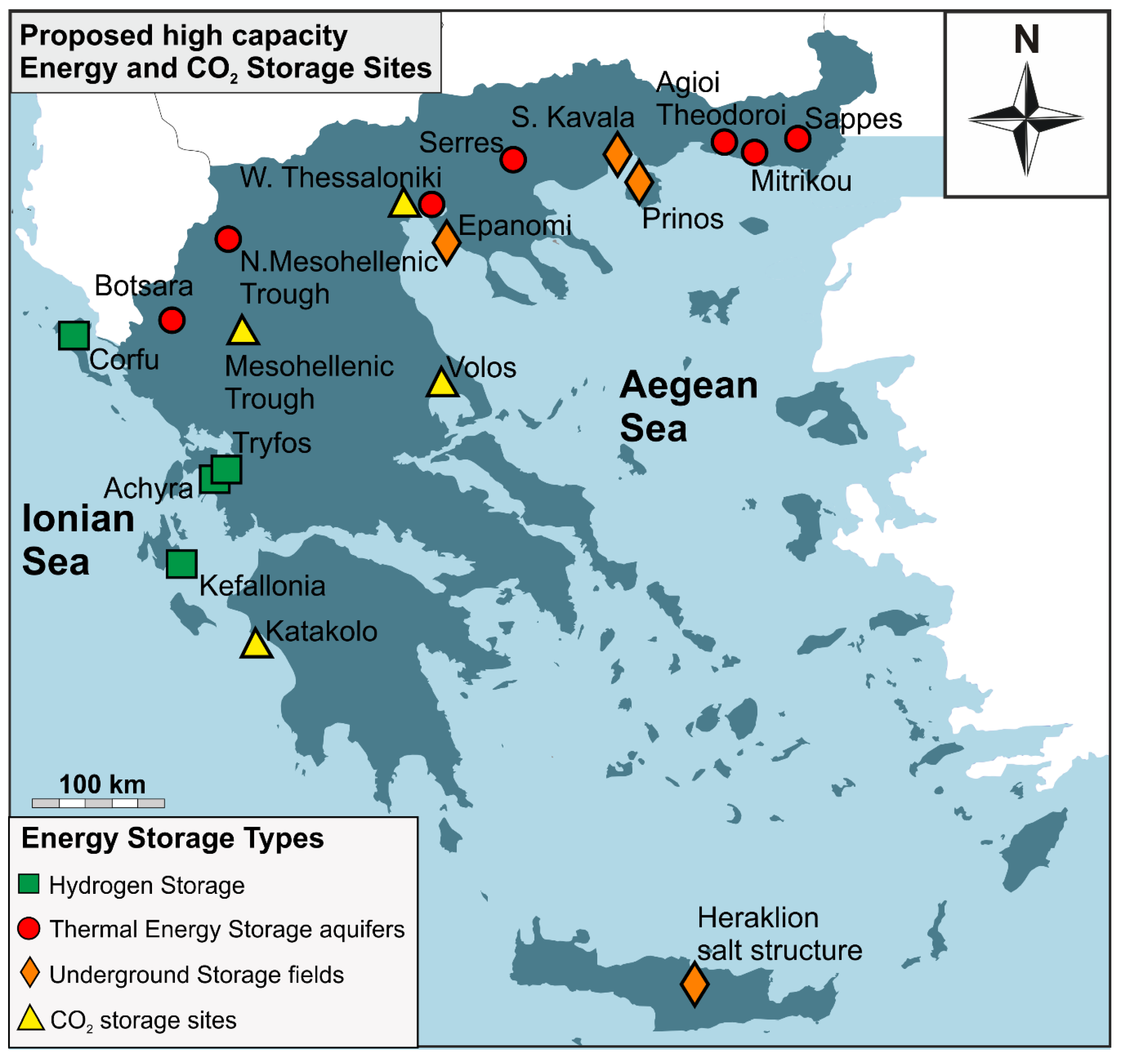
  • Thermal energy capacity was examined in 22 sandstone aquifers throughout several regions of Northern, Central Greece and Aegean islands. Research results indicate that the aquifers of Mesohellenic Trough, Western Thessaloniki basin and those of Botsara flysch exhibit the highest thermal capacity values, which can reach up to 4175 MJ.
  • Heat capacity was investigated in 14 aquifers throughout the Northern and Southern Greece, as well as on three abandoned mines from Attica region and Aliveri regions (Central Greece). In general, the aquifers tend to present higher average total heat energy values that reach up to ~6.05 × 10⁶ MWh(th) compared to those of the abandoned mines. In particular, the Sappes, Serres and Komotini (Agioi Theodoroi) aquifers could cover the space heating energy consumption of East Macedonia-Thrace region.
  • Underground gas storage technologies present better performance in the gas fields of South Kavala and Prinos basins compare to the studied evaporite formations and aquifers. These two gas fields could cover the electricity needs of the households in the region of East Macedonia and Thrace.
  • Hydrogen storage capacity was based on a capsule-shaped cavern scenario in Trifos and Achira regions (Central-Western Greece), as well as in Kefalonia and Corfu islands. Calculations indicate storage capacity of 26,600 MWh(e) for each of the studied regions. These calculated hydrogen capacity values for Corfu and Kefalonia islands, could efficiently cover the electricity needs of 6770 households in the Ionian Sea region.
  • Petrological studies of the Mesohellenic trough sandstones coupled with basaltic rocks from Volos region (Central Greece) indicate that these rocks could serve as potential sites for CO2 storage via CO2-mineralisation. This is attributed to their high porosity, low alteration grade and abundance on Fe–Mg–Ca–K silicate minerals.
  • Based on CO2 capacity data provided by the literature, geographical distribution criteria, potential for implementation of CO2 storage techniques and cost-considerations, we recommend the: (a) Volos basalts, (b) Mesohellenic trough sandstones, (c) saline aquifers of Western Thessaloniki basin and (d) the oil reservoir of Prinos basin, as the most promising sites for CO2 storage in Greece.

Supplementary Materials

The following are available online at https://www.mdpi.com/1996-1073/13/11/2707/s1, Table S1: Prop (Properties), Table S2: Assess_UGS, Table S3: Assess_H2, Table S4: Assess_Therm (Thermal Capacity), Table S5: Coordinates.

Author Contributions

Conceptualization, A.A. and P.K.; Investigation, A.A., P.K., N.K., P.T., D.K. and C.K.; Methodology, A.A., P.K., D.K. and C.K.; Supervision, A.A., P.K. and N.K.; Validation, D.K. and P.P.; Writing—original draft, A.A., P.K., N.K., P.T., D.K., C.K. and P.P. All authors have read and agreed to the published version of the manuscript.

Funding

This research received no external funding.

Acknowledgments

We would like to express our sincerest thanks to the Reviewers and the Editor for their constructive comments that substantially helped to improve the current paper. The preliminary research results provided in this paper were published in the frame of the EU Horizon 2020-funded program ESTMAP. Many thanks are also given to Georgia Kastanioti (Geologist) and Pavlos Krassakis (Geologist) for their participation of the previously mentioned EU Horizon 2020-funded project.

Conflicts of Interest

The authors declare no conflict of interest.

Appendix A

Table A1. Symbology, description of symbols and units used in equations presented in this study.
SymbolDescriptionUnit
Cpheat capacityMJ/kg·°C
rhodry bulk densitykg/m3
phiporosity%
Ttransmissivitym2/day
Khydraulic conductivitym/day
Daquifer thicknessm
Khpermeability-thickness productm2-m
PFaaverage formation pressurePa
Ttemperature°C
VISOoil viscositymm2/s
Qgproductivity gasm3/day
cvolumetric specific heat of the reservoir rockMJ/kg·°C
Vvolume of the reservoirm3
TRthe characteristic reservoir temperature°C
TREFthe reference temperature°C
Hheat in placeMJ
Vrockthe denoting rock volumem3
Prockthe rock densitykg/m3
Htotal heat energy storage capacityMJ
Peffective porosity%
ρmdensity of the rock matrixkg/m3
ρwdensity of waterkg/m3
cmspecific heat capacity of the rock matrixMJ/kg·°C
cwspecific heat capacity of waterMJ/kg·°C
Ttmean temperature of the compartment°C
Asurface area under considerationm2
Δzaquifer thicknessm
Taverageaverage temperature of stored hydrogen°C
depthdepthm
cavernHeightheight of the cavernm
KV1 = 7.5 × 10⁻⁶ m3/day
KV2 = 1 × 10⁻⁵ m3/day
Density of water: 997 kg/m3
Density of rock matrix (e.g., sandstone): 2323 kg/m3

References

  1. Davis, W. The Relationship between Atmospheric Carbon Dioxide Concentration and Global Temperature for the Last 425 Million Years. Climate 2017, 5, 76. [Google Scholar] [CrossRef] [Green Version]
  2. IPCC. Climate Change 2013: The Physical Science Basis. Contribution of Working Group I to the Fifth Assessment Report of the Intergovernmental Panel on Climate Change; Cambridge University Press: New York, NY, USA, 2013; p. 1535. [Google Scholar]
  3. Koukouzas, N.; Koutsovitis, P.; Tyrologou, P.; Karkalis, C.; Arvanitis, A. Potential for Mineral Carbonation of CO2 in Pleistocene Basaltic Rocks in Volos Region (Central Greece). Minerals 2019, 9, 627. [Google Scholar] [CrossRef] [Green Version]
  4. Rosenbauer, R.J.; Thomas, B.; Bischoff, J.L.; Palandri, J. Carbon sequestration via reaction with basaltic rocks: Geochemical modeling and experimental results. Geochim. Cosmochim. Acta 2012, 89, 116–133. [Google Scholar] [CrossRef]
  5. Bott, C.; Dressel, I.; Bayer, P. State-of-technology review of water-based closed seasonal thermal energy storage systems. Renew. Sustain. Energy Rev. 2019, 113, 109241. [Google Scholar] [CrossRef]
  6. Montcoudiol, N.; Burnside, N.M.; Györe, D.; Mariita, N.; Mutia, T.; Boyce, A. Surface and groundwater hydrochemistry of the Menengai Caldera Geothermal Field and surrounding Nakuru County, Kenya. Energies 2019, 12, 3131. [Google Scholar] [CrossRef] [Green Version]
  7. Xu, X.; Wei, Z.; Ji, Q.; Wang, C.; Gao, G. Global renewable energy development: Influencing factors, trend predictions and countermeasures. Resour. Policy 2019, 63, 101470. [Google Scholar] [CrossRef]
  8. Nataraj Barath, J.G.; Husev, O.; Manonmani, N. Overview of Energy Storage Technologies For Renewable Energy. IJISET 2015, 2, 6. [Google Scholar]
  9. Mofijur, M.; Mahlia, T.M.I.; Silitonga, A.S.; Ong, H.C.; Silakhori, M.; Hasan, M.H.; Putra, N.; Rahman, S.A. Phase Change Materials (PCM) for Solar Energy Usages and Storage: An Overview. Energies 2019, 12, 3167. [Google Scholar] [CrossRef] [Green Version]
  10. Dincer, I.; Rosen, M. Thermal Energy Storage: Systems and Applications; John Wiley & Sons: Hoboken, NJ, USA, 2010. [Google Scholar]
  11. Paksoy, H.Ö.; Beyhan, B. Thermal energy storage (TES) systems for greenhouse technology. In Advances in Thermal Energy Storage Systems. Methods and Applications; Cabeza, L.F., Ed.; Woodhead Publishing, Elsevier: Cambridge, UK, 2015; p. 612. [Google Scholar]
  12. De Schepper, G.; Paulus, C.; Bolly, P.-Y.; Hermans, T.; Lesparre, N.; Robert, T. Assessment of short-term aquifer thermal energy storage for demand-side management perspectives: Experimental and numerical developments. Appl. Energy 2019, 242, 534–546. [Google Scholar] [CrossRef] [Green Version]
  13. Park, J.-W.; Rutqvist, J.; Ryu, D.; Park, E.-S.; Synn, J.-H. Coupled thermal-hydrological-mechanical behavior of rock mass surrounding a high-temperature thermal energy storage cavern at shallow depth. Int. J. Rock Mech. Min. Sci. 2016, 83, 149–161. [Google Scholar] [CrossRef] [Green Version]
  14. Arvanitis, A. Investigation of the Possibilities for the Subsurface Energy Storage in the frame of the EC-funded ESTMAP Project. In Proceedings of the 11th National Conference on Renewable Energy Sources, Thessaloniki, Greece, 14–16 March 2018. [Google Scholar]
  15. Breeze, P. Power System Energy Storage Technologies. In Power Generation Technologies, 3rd ed.; Breeze, P., Ed.; Elsevier Ltd.: Amsterdam, The Netherlands, 2019; pp. 219–249. [Google Scholar]
  16. Lemieux, A.; Sharp, K.; Shkarupin, A. Preliminary assessment of underground hydrogen storage sites in Ontario, Canada. Int. J. Hydrog. Energy 2019, 44, 15193–15204. [Google Scholar] [CrossRef]
  17. Caglayan, D.; Weber, N.; Heinrichs, H.; Linssen, J.; Robinius, M.; Kukla, P.; Stolten, D. Technical potential of salt caverns for hydrogen storage in Europe. Int. J. Hydrog. Energy 2020, 45, 6793–6805. [Google Scholar] [CrossRef]
  18. Crotogino, F.; Donadei, S.; Bünger, U.; Landinger, H. Large-Scale Hydrogen Underground Storage for Securing Future Energy Supplies. In Proceedings of the 18th World Hydrogen Energy Conference, Essen, Germany, 16–21 May 2010. [Google Scholar]
  19. Arvanitis, A.; Koukouzas, N.; Koutsovitis, P.; Karapanos, D.; Manoukian, E. Combined CO2 Geological Storage and Geothermal Energy Utilization in Greece. In Proceedings of the 15th International Congress of the Geological Society of Greece Harokopio University of Athens, Athens, Greece, 22–24 May 2019. [Google Scholar]
  20. Hasan, M.M.F.; Boukouvala, F.; First, E.L.; Floudas, C.A. Nationwide, Regional, and Statewide CO2 Capture, Utilization, and Sequestration Supply Chain Network Optimization. Ind. Eng. Chem. Res 2014, 53, 7489–7506. [Google Scholar] [CrossRef]
  21. Celia, M.A.; Bachu, S.; Nordbotten, J.M.; Bandilla, K.W. Status of CO2 storage in deep saline aquifers with emphasis on modeling approaches and practical simulations. Water Resour. Res. 2015, 51, 6846–6892. [Google Scholar] [CrossRef]
  22. Jalili, P.; Saydam, S.; Cinar, Y. CO2 Storage in Abandoned Coal Mines. In Proceedings of the Underground Coal Operators’ Conference Wollongong, Wollongong, Australia, 10–11 February 2011; p. 410. [Google Scholar]
  23. Xie, L.Z.; Zhou, H.; Xie, H. Research advance of CO2 storage in rock salt caverns. Yantu Lixue/Rock Soil Mech. 2009, 30, 7. [Google Scholar]
  24. Baran, P.; Zarębska, K.; Krzystolik, P.; Hadro, J.; Nunn, A. CO2-ECBM and CO2 sequestration in Polish coal seam—Experimental study. J. Sustain. Min. 2014, 13, 22–29. [Google Scholar] [CrossRef] [Green Version]
  25. Raza, A.; Gholami, R.; Rezaee, R.; Bing, C.H.; Nagarajan, R.; Hamid, M.A. Well selection in depleted oil and gas fields for a safe CO2 storage practice: A case study from Malaysia. Petroleum 2017, 3, 167–177. [Google Scholar] [CrossRef]
  26. Györe, D.; Stuart, F.M.; Gilfillan, S.M.V.; Waldron, S. Tracing injected CO2 in the Cranfield enhanced oil recovery field (MS, USA) using He, Ne and Ar isotopes. Int. J. Greenh. Gas Control 2015, 42, 554–561. [Google Scholar] [CrossRef] [Green Version]
  27. Snæbjörnsdóttir, S.Ó.; Wiese, F.; Fridriksson, T.; Ármansson, H.; Einarsson, G.M.; Gislason, S.R. CO2 storage potential of basaltic rocks in Iceland and the oceanic ridges. Energy Procedia 2014, 63, 4585–4600. [Google Scholar] [CrossRef] [Green Version]
  28. Ragnheidardottir, E.; Sigurdardottir, H.; Kristjansdottir, H.; Harvey, W. Opportunities and challenges for CarbFix: An evaluation of capacities and costs for the pilot scale mineralization sequestration project at Hellisheidi, Iceland and beyond. Int. J. Greenh. Gas Control 2011, 5, 1065–1072. [Google Scholar] [CrossRef]
  29. Koukouzas, N.; Kypritidou, Z.; Purser, G.; Rochelle, C.A.; Vasilatos, C.; Tsoukalas, N. Assessment of the impact of CO2 storage in sandstone formations by experimental studies and geochemical modeling: The case of the Mesohellenic Trough, NW Greece. Int. J. Greenh. Gas Control 2018, 71, 116–132. [Google Scholar] [CrossRef]
  30. Garcia-Rios, M.; Luquot, L.; Soler, J.; Cama, J. Laboratory-Scale Interaction between CO2-Rich Brine and Reservoir Rocks (Limestone and Sandstone). Procedia Earth Planet. Sci. 2013, 7, 109–112. [Google Scholar] [CrossRef] [Green Version]
  31. Boschi, C.; Dini, A.; Dallai, L.; Ruggieri, G.; Gianelli, G. Enhanced CO2-mineral sequestration by cyclic hydraulic fracturing and Si-rich fluid infiltration into serpentinites at Malentrata (Tuscany, Italy). Chem. Geol. 2009, 265, 209–226. [Google Scholar] [CrossRef]
  32. Dichicco, M.C.; Laurita, S.; Paternoster, M.; Rizzo, G.; Sinisi, R.; Mongelli, G. Serpentinite Carbonation for CO2 Sequestration in the Southern Apennines: Preliminary Study. Energy Procedia 2015, 76, 477–486. [Google Scholar] [CrossRef] [Green Version]
  33. Bennaceur, K. CO2 Capture and Sequestration. In Future Energy, 2nd ed.; Letcher, T.M., Ed.; Elsevier: Amsterdam, The Netherlands, 2014; pp. 583–611. [Google Scholar]
  34. Piessens, K.; Dusar, M. CO2-sequestration in abandoned coal mines. In Proceedings of the International Coalbed Methane Symposium, Tuscaloosa, AL, USA, 5–8 May 2003; p. 11. [Google Scholar]
  35. Kelektsoglou, K. Carbon Capture and Storage: A Review of Mineral Storage of CO2 in Greece. Sustainability 2018, 10, 4400. [Google Scholar] [CrossRef] [Green Version]
  36. Petrounias, P.; Giannakopoulou, P.; Rogkala, A.; Kalpogiannaki, M.; Koutsovitis, P.; Damoulianou, M.-E.; Koukouzas, N. Petrographic Characteristics of Sandstones as a Basis to Evaluate Their Suitability in Construction and Energy Storage Applications. A Case Study from Klepa Nafpaktias (Central Western Greece). Energies 2020, 13, 1119. [Google Scholar] [CrossRef] [Green Version]
  37. Tasianas, A.; Koukouzas, N. CO2 storage capacity estimate in the lithology of the Mesohellenic Trough, Greece. Energy Procedia 2016, 86, 334–341. [Google Scholar] [CrossRef] [Green Version]
  38. Koukouzas, N.; Gemeni, V.; Ziock, H.J. Sequestration of CO2 in magnesium silicates, in Western Macedonia, Greece. Int. J. Miner. Process. 2009, 93, 179–186. [Google Scholar] [CrossRef]
  39. ESTMAP, Energy Storage Mapping and Planning Home Page. Available online: http://estmap.eu/deliverables.html (accessed on 5 May 2020).
  40. Karakitsios, V. Western Greece and Ionian Sea petroleum systems. AAPG Bull. 2013, 97, 1567–1595. [Google Scholar] [CrossRef] [Green Version]
  41. Karakitsios, V.; Rigakis, N. Evolution and petroleum potential of Western Greece. J. Pet. Geol. 2007, 30, 197–218. [Google Scholar] [CrossRef]
  42. Tserolas, P.; Mpotziolis, C.; Maravelis, A.; Zelilidis, A. Preliminary Geochemical and Sedimentological Analysis in NW Corfu: The Miocene Sediments in Agios Georgios Pagon. In Proceedings of the 14th International Congress of Geological Society of Greece, Thessaloniki, Greece, 25–27 May 2016; pp. 402–411. [Google Scholar]
  43. Karakitsios, V.; Roveri, M.; Lugli, S.; Manzi, V.; Gennari, R.; Antonarakou, A.; Triantaphyllou, M.; Agiadi, K.; Kontakiotis, G.; Kafousia, N.; et al. A Record of the Messinian Salinity Crisis in the Eastern Ionian Tectonically Active Domain (Greece, Eastern Mediterrenean). Basin Res. 2017, 29, 203–233. [Google Scholar] [CrossRef]
  44. Kokinou, E.; Kamberis, E.; Kotsi, F.; Lioni, K.; Velaj, T. The Impact of Evaporites in the Greek and Albanian Oil Systems. In Proceedings of the 79th EAGE Conference and Exhibition 2017, Paris, France, 12–15 June 2017. [Google Scholar]
  45. Velaj, T. The structural style and hydrocarbon exploration of the subthrust in the Berati Anticlinal Belt, Albania. J. Pet. Explor. Prod. Technol. 2015, 5, 123–145. [Google Scholar] [CrossRef] [Green Version]
  46. Velaj, T. Tectonic style in Western Albania Thrustbelt and its implication on hydrocarbon exploration. AAPG Search Discov. Artic. 2011, 123–148. [Google Scholar]
  47. Kontopoulos, N.; Zelilidis, A.; Piper, D.J.W.; Mudie, P.J. Messinian evaporites in Zakynthos, Greece. Palaeogeogr. Palaeoclimatol. Palaeoecol. 1997, 129, 361–367. [Google Scholar] [CrossRef]
  48. Bourli, N.; Kokkaliari, M.; Iliopoulos, I.; Pe-Piper, G.; Piper, D.J.W.; Maravelis, A.G.; Zelilidis, A. Mineralogy of siliceous concretions, cretaceous of ionian zone, western Greece: Implication for diagenesis and porosity. Mar. Pet. Geol. 2019, 105, 45–63. [Google Scholar] [CrossRef]
  49. Tsipoura-Vlachou, M. Diagenesis of the Marly-Gypsum Formations, Igoumenitsa Area, N.W. Greece. Bull. Geol. Soc. Greece 2007, 40, 1009–1021. [Google Scholar] [CrossRef]
  50. Getsos, K.; Papaioannou, F.; Zelilidis, A. Triassic Carbonate and Evaporite Sedimentation in the Ionian Zone (Western Greece): Palaeogeographic and Palaeoclimatic Implication. Bull. Geol. Soc. Greece 2004, 36, 699–707. [Google Scholar] [CrossRef] [Green Version]
  51. Flugel, E. Mikrofazielle Untersuchungen in der Alpinen Trias: Methoden and Probleme. Mitt. Ges. Geol. Bergbaustud. 1972, 21, 9–64. [Google Scholar]
  52. Vamvaka, A.; Spiegel, C.; Frisch, W.; Danisik, M. Fission track data from the Mesohellenic Trough and the Pelagonian zone in NW Greece: Cenozoic tectonics and exhumation of source areas. Int. Geol. Rev. 2010, 52, 223–248. [Google Scholar] [CrossRef]
  53. Rassios, A.; Moores, E. Heterogeneous mantle complex, crustal processes, and obduction kinematics in a unified Pindos-Vourinos ophiolitic slab (northern Greece). Geol. Soc. Lond. Spec. Publ. 2006, 260, 237–266. [Google Scholar] [CrossRef]
  54. Kilias, A.; Vamvaka, A.; Falalakis, G.; Sfeikos, A.; Papadimitriou, E.; Gkarlaouuni, C.; Karakostas, B. The Mesohellenic Trough and the Paleogene Thrace Basin on the Rhodope Massif, their Structural Evolution and Geotectonic Significance in the Hellenides. J. Geol. Geosci. 2015, 4, 2. [Google Scholar] [CrossRef] [Green Version]
  55. Brunn, J.H. Contribution à l’étude géologique du Pinde septentrional et d’une partie de la Macédoine occidentale. Ann. Géol. Pays Hell. 1956, 8, 346–358. [Google Scholar]
  56. Papanikolaou, D.; Lekkas, E.; Mariolakos, H.; Mirkou, R. Contribution on the geodynamic evolution of the Mesohellenic trough. Bull. Geol. Soc. Greece 1988, 20, 17–36. [Google Scholar]
  57. Aubouin, J. Contribution à l’ étude géologique de la Grèce septentrionale: Le confins de l’ Epire et de la Thessalie. Ann. Géol. Pays Hell. 1959, 10, 525. [Google Scholar]
  58. Koukouzas, C.; Koukouzas, N. Coals of Greece: Distribution, quality and reserves. Geol. Soc. Spec. Publ. 1995, 82, 171–180. [Google Scholar] [CrossRef]
  59. Wilson, M.; Monea, M. IEA GHG Weyburn CO2 monitoring and storage project: Summary report 2000–2001. In Proceedings of the 7th International Conference Greenhouse Gas Control Technology (GHGT-7), Vancouver, BC, Canada, 5–9 September 2005. [Google Scholar]
  60. Koukouzas, N.; Ziogou, F.; Gemeni, V. Preliminary assessment of CO2 geological storage opportunities in Greece. Int. J. Greenh. Gas Control 2009, 3, 502–513. [Google Scholar] [CrossRef]
  61. Tasianas, A.; Koukouzas, N. Assessing the Potential of the Mesohellenic Trough and Other Sites, in Greece, for CO2 Storage. Procedia Earth Planet. Sci. 2015, 15, 607–612. [Google Scholar] [CrossRef] [Green Version]
  62. Saccani, E.; Photiades, A. Mid-ocean ridge and supra-subduction affinities in the Pindos ophiolites (Greece): Implications for magma genesis in a forearc setting. Lithos 2004, 73, 229–253. [Google Scholar] [CrossRef]
  63. Pomonis, P.; Tsikouras, B.; Hatzipanagiotou, K. Geological evolution of the Koziakas ophiolitic complex (W. Thessaly, Greece). Ofioliti 2005, 30, 77–86. [Google Scholar]
  64. Koutsovitis, P. Gabbroic rocks in ophiolitic occurrences from East Othris, Greece: Petrogenetic processes and geotectonic environment implications. Mineral. Petrol. 2011, 104, 249–265. [Google Scholar] [CrossRef]
  65. Saccani, E.; Beccaluva, L.; Photiades, A.; Zeda, O. Petrogenesis and tectono-magmatic significance of basalts and mantle peridotites from the Albanian–Greek ophiolites and sub-ophiolitic mélanges. New constraints for the Triassic–Jurassic evolution of the Neo-Tethys in the Dinaride sector. Lithos 2011, 124, 227–242. [Google Scholar] [CrossRef]
  66. Stouraiti, C.; Pantziris, I.; Vasilatos, C.; Kanellopoulos, C.; Mitropoulos, P.; Pomonis, P.; Moritz, R.; Chiaradia, M. Ophiolitic Remnants from the Upper and Intermediate Structural Unit of the Attic-Cycladic Crystalline Belt (Aegean, Greece): Fingerprinting Geochemical Affinities of Magmatic Precursors. Geosciences 2017, 7, 14. [Google Scholar] [CrossRef] [Green Version]
  67. Mortazavi, M.; Sparks, R. Origin of rhyolite and rhyodacite lavas and associated mafic inclusions of Cape Akrotiri, Santorini: The role of wet basalt in generating calcalkaline silicic magmas. Contrib. Mineral. Petrol. 2004, 146, 397–413. [Google Scholar] [CrossRef]
  68. Bachmann, O.; Deering, C.; Ruprecht, J.; Huber, C.; Skopelitis, A.; Schnyder, C. Evolution of silicic magmas in the Kos-Nisyros volcanic center, Greece: A petrological cycle associated with caldera collapse. Contrib. Mineral. Petrol. 2012, 163, 151–166. [Google Scholar] [CrossRef]
  69. Pe-Piper, G.; Panagos, A.G. Geochemical characteristics of the Triassic volcanic rocks of Evia: Petrogenetic and tectonic implications. Ofioliti 1989, 14, 33–50. [Google Scholar]
  70. Pe-Piper, G.; Piper, D. Neogene backarc volcanism of the Aegean: New insights into the relationship between magmatism and tectonics. Geol. Soc. Am. 2007, 418, 17–31. [Google Scholar] [CrossRef]
  71. Fytikas, M.; Innocenti, F.; Manetti, P.; Peccerillo, A.; Mazzuoli, R.; Villari, L. Tertiary to Quaternary evolution of volcanism in the Aegean region: The Geological Evolution of the Eastern Mediterranean. In Geological Society Special Publication; Dixon, J.E., Robertson, A.H.F., Eds.; The Geological Society Publishing House: Bath, UK, 1984; Volume 17, pp. 687–699. [Google Scholar]
  72. Innocenti, F.; Agostini, S.; Doglioni, C.; Piero, M.; Tonarini, S. Geodynamic evolution of the Aegean: Constraints from the Plio-Pleistocene volcanism of the Volos-Evia area. J. Geol. Soc. Lond. 2010, 167, 475–489. [Google Scholar] [CrossRef]
  73. Nicholls, I.A. Petrology of Santorini Volcano, Cyclades, Greece. J. Petrol. 1971, 12, 67–119. [Google Scholar] [CrossRef]
  74. Nicholls, I.A. Santorini volcano, greece—Tectonic and petrochemical relationships with volcanics of the Aegean region. Tectonophysics 1971, 11, 377–385. [Google Scholar] [CrossRef]
  75. Bridger, D.W.; Allen, D.M. Designing aquifer thermal energy storage systems. ASHRAE J. 2005, 47, S32. [Google Scholar]
  76. Vance, D. Heat in Groundwater Systems Part I—The Fundamentals. Natl. Environ. J. 1996, 6, 30–31. [Google Scholar]
  77. Brandt, M.J.; Johnson, K.M.; Elphinston, A.J.; Ratnayaka, D.D. Twort’s Water Supply, 7th ed.; Elsevier: Amsterdam, The Netherlands, 2017. [Google Scholar]
  78. Maidment, D.R. Handbook of Hydrology; McGraw-Hill: New York, NY, USA, 1992. [Google Scholar]
  79. Price, M. Introducing Groundwater, 2nd ed.; Chapman and Hall: London, UK, 1996. [Google Scholar]
  80. Crain, E.R. Crain’s Petrophysical Handbook; Spectrum 2000 Mindware: Rocky Mountain House, AB, Canada, 1987. [Google Scholar]
  81. Nathenson, M. Physical Factors Determining the Fraction of Stored Energy Recoverable from Hydrothermal Convection Systems and Conduction-Dominated Areas; U.S. Geological Survey Open-File Report: Menlo Park, CA, USA, 1975; p. 50. [Google Scholar]
  82. White, D.E.; Williams, D.L. Assessment of Geothermal Resources of the United Sates; U.S. Geological Survey Circular: Arlington, VA, USA, 1975; p. 155. [Google Scholar]
  83. Muffler, L.J.P. Assessment of Geothermal Resources of the United States; U.S. Geological Survey Circular: Roosevelt, UT, USA, 1979; p. 163. [Google Scholar]
  84. Franco, A.; Donatini, F. Methods for the estimation of the energy stored in geothermal reservoirs. J. Phys. Conf. Ser. 2017, 796, 012025. [Google Scholar] [CrossRef] [Green Version]
  85. Beardsmore, G.; Rybach, L.; Blackwell, D.; Baron, C. A Protocol for Estimating and Mapping Global EGS Potential. GRC Trans. 2010, 34, 301–312. [Google Scholar]
  86. Gao, L.; Zhao, J.; An, Q.; Liu, X.; Du, Y. Thermal performance of medium-to-high-temperature aquifer thermal energy storage systems. Appl. Therm. Eng. 2019, 146, 898–909. [Google Scholar] [CrossRef]
  87. Van Lopik, J.H.; Hartog, N.; Jan Zaadnoordijk, W. The use of salinity contrast for density difference compensation to improve the thermal recovery efficiency in high-temperature aquifer thermal energy storage systems. Hydrogeol. J. 2016, 24, 1255–1271. [Google Scholar] [CrossRef] [Green Version]
  88. Berger, B.; Anderson, K. Modern Petroleum: A Basic Primer of the Industry, 3rd ed.; Pennwell Books: Houston, TX, USA, 1992; p. 517. [Google Scholar]
  89. North, F.K. Petroleum Geology; Allen & Unwin: Boston, MA, USA, 1985. [Google Scholar]
  90. Franz, P.; Neville-Lamb, M.; Azwar, L.; Quinao, J. Calculation of Geothermal Stored Heat from a Numerical Model for Reserve Estimation. In Proceedings of the World Geothermal Congress, Melbourne, Australia, 19–25 April 2015. [Google Scholar]
  91. Muffler, P.; Cataldi, R. Methods for regional assessment of geothermal resources. Geothermics 1978, 7, 53–89. [Google Scholar] [CrossRef]
  92. Schellschmidt, R.; Hurter, S. Atlas of Geothermal Resources in Europe. Geothermics 2003, 32, 779–787. [Google Scholar] [CrossRef]
  93. Pellegrini, M.; Bloemendal, M.; Hoekstra, N.; Spaak, G.; Andreu Gallego, A.; Rodriguez Comins, J.; Grotenhuis, T.; Picone, S.; Murrell, A.J.; Steeman, H.J. Low carbon heating and cooling by combining various technologies with Aquifer Thermal Energy Storage. Sci. Total Environ. 2019, 665, 1–10. [Google Scholar] [CrossRef]
  94. Todorov, O.; Alanne, K.; Virtanen, M.; Kosonen, R. A method and analysis of aquifer thermal energy storage (ATES) system for district heating and cooling: A case study in Finland. Sustain. Cities Soc. 2020, 53, 101977. [Google Scholar] [CrossRef]
  95. Hooimeijer, F.; Maring, L. The significance of the subsurface in urban renewal. IRPUS 2018, 11, 303–328. [Google Scholar] [CrossRef] [Green Version]
  96. Kostakis, I. Socio-demographic determinants of household electricity consumption: Evidence from Greece using quantile regression analysis. CRSUST 2020, in press. [Google Scholar] [CrossRef]
  97. Azeiteiro, U.; Davim, J. Higher Education and Sustainability, 1st ed.; CRC Press: Boca Raton, FL, USA, 2020. [Google Scholar]
  98. Tichler, R.; Bauer, S. Power to gas. In Storing Energy with Special Reference to Renewable Energy Sources; Letcher, T.M., Ed.; Elsevier: Oxford, UK, 2016; p. 590. [Google Scholar]
  99. Renpu, W. Basis of Well Completion Engineering. In Advanced Well Completion Engineering, 3rd ed.; Renpu, W., Ed.; Gulf Professional Publishing: Oxford, UK, 2011; pp. 1–74. [Google Scholar]
  100. Speight, J.G. Recovery, storage, and transportation. In Natural Gas, 2nd ed.; Speight, J.G., Ed.; Gulf Professional Publishing: Boston, MA, USA, 2019; pp. 149–186. [Google Scholar]
  101. Speight, J.G. (Ed.) Reservoirs and Reservoir Fluids. In Handbook of Hydraulic Fracturing; Wiley: Hoboken, NJ, USA, 2016; pp. 27–54. [Google Scholar]
  102. Papadopoulou, D.; Tourkolias, C.N.; Mirasgedis, S. Assessing the macroeconomic effect of gas pipeline projects: The case of Trans-Adriatic Pipeline on Greece. SPOUDAI 2015, 65, 100–118. [Google Scholar]
  103. Khalova, G.O.; Illeritskiy, N.I.; Smirnova, V.A. Prospects for the Construction of the Poseidon Gas Pipeline as a Factor in Supplying the Needs of the Southern Europe Countries with Natural Gas. Int. J. Energy Econom. Policy 2019, 9, 143–148. [Google Scholar]
  104. Kotek, P.; Granado, P.C.d.; Egging, R.; Toth, B.T. European Natural Gas Infrastructure in the Energy Transition. In Proceedings of the 16th International Conference on the European Energy Market (EEM), Ljubljana, Slovenia, 18–20 September 2019; pp. 1–6. [Google Scholar]
  105. Kitsilis, M.-C. Issues for Underground Gas Storage (UGS) in ‘South Kavala’ offshore gas field. In Proceedings of the 5th South East Europe Energy Dialogue, Thessaloniki, Greece, 2–3 June 2011. [Google Scholar]
  106. Ozarslan, A. Large-scale hydrogen energy storage in salt caverns. Int. J. Hydrog. Energy 2012, 37, 14265–14277. [Google Scholar] [CrossRef]
  107. Winter, C.-J.; Nitch, J. Hydrogen as an Energy Carrier: Technologies, Systems, Economy; Spiringer: Stuttgart, Germany, 1988. [Google Scholar]
  108. Eiken, O.; Ringrose, P.; Hermanrud, C.; Nazarian, B.; Torp, T.A.; Høier, L. Lessons learned from 14 years of CCS operations: Sleipner, In Salah and Snøhvit. Energy Procedia 2011, 4, 5541–5548. [Google Scholar] [CrossRef] [Green Version]
  109. Beaubien, S.E.; Jones, D.G.; Gal, F.; Barkwith, A.K.A.P.; Braibant, G.; Baubron, J.-C.; Ciotoli, G.; Graziani, S.; Lister, T.R.; Lombardi, S.; et al. Monitoring of near-surface gas geochemistry at the Weyburn, Canada, CO2-EOR site, 2001–2011. Int. J. Greenh. Gas Control 2013, 16, S236–S262. [Google Scholar] [CrossRef]
  110. Andritsos, N.; Arvanitis, A.; Papachristou, M.; Fytikas, M.; Dalabakis, P. Geothermal Activities in Greece During 2005-2009. In Proceedings of the World Geothermal Congress Bali, Bali, Indonesia, 25–29 April 2010; pp. 25–29. [Google Scholar]
  111. Jin, C.; Liu, L.; Yiman, l.; Zeng, R. Capacity assessment of CO2 storage in deep saline aquifers by mineral trapping and the implications for Songliao Basin, Northeast China. Energy Sci. Eng. 2017, 5, 81–89. [Google Scholar] [CrossRef]
  112. Hannis, S.; Lu, J.; Chadwick, A.; Hovorka, S.; Kirk, K.; Romanak, K.; Pearce, J. CO2 storage in depleted or depleting oil and gas fields: What can we learn from existing projects? Energy Procedia 2017, 114, 5680–5690. [Google Scholar] [CrossRef]
Figure 1. Main proposed high capacity energy and CO2 storage sites (hydrogen storage: 26,600 MWh[e]; Thermal Capacity: 2930–4651 MJ; Gas Storage Capacity: 928,097–4,826,105 MWh[e]; CO2 storage: 27,600 t [3] to 1350 Mt [19].
Energies 13 02707 g001
Figure 2. (a) Geological map of the Mesohellenic Trough region, WGS’84 and (b) Cross section displaying the potential site for energy storage purposes.
Energies 13 02707 g002
Figure 3. XRD patterns of Mesohellenic Trough sandstone sample (West Macedonia).
Energies 13 02707 g003
Figure 4. (a,b) Mesohellenic Trough sandstone photomicrographs including feldspar fragments (Fsp) within quartz (Qz) rich groundmass. Calcite (Cc) and muscovite (Ms) appear in the form of accessory minerals. (c,d) Basaltic rock samples presenting porphyritic textures composed by plagioclase (Pl) rich groundmass and clinopyroxene (Cpx) phenocrysts. Gas vesicles have been partially filled with secondary calcite (Cc).
Energies 13 02707 g004
Figure 5. Thermal capacity column chart of the studied Greek aquifers.
Energies 13 02707 g005
Figure 6. Average total heat energy column chart of the studied Greek aquifers and abandoned mines.
Energies 13 02707 g006
Figure 7. Average area heat energy column chart of the studied Greek aquifers and abandoned mines.
Energies 13 02707 g007
Figure 8. Average energy storage capacity (MWh[e]) column chart of the studied Greek aquifers, evaporites and abandoned mines.
Energies 13 02707 g008
Table 1. Thermal Capacity properties of Aquifers from selected localities.
Aquifers ConsideredThermal Capacity (MJ)Productivity (m3/day)Heat in Place (MJ)
Sappes3.3703533 × 10−3
Agioi Theodoroi-Komotini2.93011933 × 10−3
Mitrikou lake3.0097889 × 10−4
Serres2.43511,1691 × 10−3
W. Thessaloniki Shallow Thermal2.3821624 × 10−4
W. Thessaloniki-Alexandria3.57715161 × 10−3
Mesohellenic Trough_ South Grevena3.70057,70925 × 10−3
Flysch Botsara syncline3.82264,30418 × 10−3
Aliveri Evia2.7034051 × 10−3
Megalopoli2.2911094 × 10−4
Thimiana Chios3.021805 × 10−4
Lesbos-Thermi2.88544.52 × 10−3
Kos2.3944041 × 10−3
Samos2.46137.57 × 10−4
Limnos2.69238.51 × 10−3
Rhodes2.2498329 × 10−4
Mesohellenic Trough_Felio4.17592,74718 × 10−3
W. Thessaloniki_ SG3.9311,0827 × 10−3
W. Thessaloniki_ DG4.65132531 × 10−3
Fili landfill_Attica2.58943521 × 10−3
North Mesohellenic basin_ SG3.70043,28222 × 10−3
North Mesohellenic basin_ DG4.00693,7783 × 10−3
(Data was collected on potential and possible locations for various underground energy storage technologies in aquifers—see Supplementary Table S1 for more details).
Table 2. Transmissivity properties of the studied aquifers (see Supplementary Table S1 for more properties).
Aquifers ConsideredTransmissivity (m2)
Aquifer Sappes6.9 × 10−14
Aquifer Agioi Theodoroi-Komotinis2.21 × 10−13
Aquifer Mitrikou lake1.77 × 10−13
Aquifer Serres4.14 × 10−13
Aquifer Western Thessaloniki_Shallow Thermal5.92 × 10−14
Aquifer_Western Thessaloniki_Alexandria1.18 × 10−13
Aquifer_Mesohellenic Trough_South Grevena1.97 × 10−12
Aquifer Flysch Botsara syncline2.96 × 10−13
Aquifer Aliveri Evia3.45 × 10−13
Aquifer Megalopoli7.89 × 10−14
Aquifer Thimiana Chios7.4 × 10−14
Aquifer Lesbos-Thermi island5.92 × 10−15
Aquifer Kos island6.9 × 10−13
Aquifer Samos island2.96 × 10−14
Aquifer Limnos island2.96 × 10−14
Aquifer Rhodes1.18 × 10−13
Aquifer_Mesohellenic Trough_Felio1.48 × 10−12
Aquifer_Western Thessaloniki_SG2.96 × 10−13
Aquifer_Western Thessaloniki_DG8.29 × 10−14
Aquifer_Fili landfill_Attica2.24 × 10−13
North Mesohellenic basin_SG1.97 × 10−12
North Mesohellenic basin_DG1.48 × 10−12
Table 3. Underground Thermal energy storage systems (UTES) Capacity in selected sites (see Supplementary Table S2 for additional details).
Sites Considered (* Aquifer, ** Abandoned Mine)Avgerage Total Heat Energy Storage Capacity (MWh[th])Average Area Heat Energy Storage Capacity (MWh[th])
Sappes *2,172,6171,284,404
Agioi Theodoroi Komotinis *4,076,8311,365,479
Mitrikou lake *1,335,808448,048
Serres *6,052,932793,685
W. Thessaloniki Shallow Thermal *13,232249,200
Aliveri Evia *723,255691,274
Megalopoli *384,557227,864
Thimiana Chios *9599256,027
Lesbos-Thermi *509,1671,024,109
Kos *847,815836,356
Samos *21,801384,041
Limnos *767,700473,650
Rhodes *162,278477,918
Fili landfill_Attica *673,119621,720
Mandra Attica **34,5432,997,653
Aliveri **936,9385,440,280
Chaidari **65,1981,181,993
Table 4. Underground gas storage (UGS) Capacity in selected sites (see Supplementary Table S3 for additional details).
Sites Considered (* Gas Field, ** Aquifer, *** Salt Structure)Total Gas Volume (Mm3)Working Gas Volume (Mm3)Cushion Gas Volume (Mm3)Energy Storage Capacity (MWh[e])
South Kavala *8477201272,672,920
Epanomi *500250250928,097
Katakolo *300150150556,858
Prinos *228013009804,826,105
Western Thessaloniki_ Alexandria **3123712
Mesohellenic Trough_ South Grevena **44133148,261
Flysch Botsara syncline **33102337,123
Mazarakia ***281175106649,668
Heraklion ***328204124757,327
Mesohellenic Trough Filio **2581729,699
Western Thessaloniki SG **1364195152,208
Western Thessaloniki DG **299320345,252
North Mesohellenic basin SG **1303991144,783
North Mesohellenic basin DG **21464150237,593
Delvinaki ***218175106649,668

