Article

Practical Energy Retrofit of Heat Exchanger Network Not Containing Utility Path

Institute of Process Engineering, Faculty of Mechanical Engineering, Brno University of Technology, Technická 2, 616 69 Brno, Czech Republic
*
Author to whom correspondence should be addressed.
Energies 2020, 13(11), 2711; https://doi.org/10.3390/en13112711
Submission received: 21 April 2020 / Revised: 17 May 2020 / Accepted: 21 May 2020 / Published: 28 May 2020
(This article belongs to the Section J: Thermal Management)

Abstract

:
The paper presents a method developed for the energy retrofit of specific Heat Exchanger Networks not containing Utility Paths. This useful and highly practically oriented method involves a systematic approach to obtaining the most efficient minimal modification topology of a Heat Exchanger Network, which brings the greatest benefits in terms of energy savings of the modified process. In principle, it is focused on finding the most suitable location for a new heat exchanger insertion to create the most efficient Utility Path. The next step of the developed retrofit method is the detailed design of the newly integrated heat exchanger using commercial software in combination with several heuristic rules regarding the cost-free investment and maintenance cost minimization of a new heat exchanger and considering heat transfer enhancement within the available exchanger type, space, and fluids pressure drop constraints. The detail design stage of the method also includes observation and reassessment of the performance and operational parameters of the existing heat exchangers. Then, the developed method is applied to the case of the Heat Exchanger Network retrofit in the process of the hydrogenation of oil.

Graphical Abstract

1. Introduction

The continuing need to improve energy efficiency in the chemical, petrochemicals, power, and other process industries leads to continually increasing interest in retrofitting Heat Exchanger Networks (HENs). Such a retrofit is currently based on applying some of the Heat Integration strategies developed for the utilization of waste process heat and/or for recovery of more of the heat available in the process streams. The most common reasons for HEN retrofit include allowing to satisfy process heating and cooling demands with reduced process dependence on external utilities (energy retrofit), the need to increase the production capacity of the process limited by the duty of the utility system, especially by the duty of fired heater (debottlenecking retrofit) and/or the need to adapt the process to processing of the changed feed type or its behavior (feed/process modification retrofit).
Up-to-date strategies for HEN retrofit presented in several reports in the literature are based especially on Pinch Analysis, mathematical programming, or a combination of both these approaches (hybrid methods). A comprehensive and detail review of the all mentioned methods for HEN retrofit was presented by Sreepathi and Rangaiah [1].
Pinch Analysis (or Pinch Technology) represents a historically very important approach for the efficient use of energy and other raw materials, such as water, hydrogen, etc. The discovery of the Pinch Analysis concept and the beginnings of its development are dated to the late 1970s and are most commonly associated with the works of Hohman [2], Huang and Elshout [3], Umeda et al. [4], and especially then Linnhoff et al. [5,6]. From this perspective, it can be stated that the method for HEN retrofit based on Pinch Analysis presented by Tjoe and Linnhoff [7] can be considered as the first system approach to HEN retrofit. The main objective of their work is to eliminate a heat transfer across the Pinch. This concept has been later extended to account for the cost required in HEN retrofit by Carlsson et al. [8]. In the following years, further intensive development of the Pinch Analysis-based HEN retrofit method occurred. One of the important aspects of this development was also the graphical or visualization methods and tools for HEN retrofit, such as the Retrofit Thermodynamic Diagram (RTD), which has been developed by Lakshmanan and Bañares-Alcántara [9] and further extended later by Lakshmanan and Bañares-Alcántara [10]. The latest work in this area is, for example, the work of Yong et al. [11] introducing the Shifted Retrofit Thermodynamic Grid Diagram (SRTGD) for Heat Path development to enable Heat Recovery improvement or the work of Gadalla [12], who presented a new graphical method based on Pinch Analysis. His method quantitatively evaluates the energy efficiency in the existing HEN to identify the potential modifications for better Energy Recovery. Recent important works in HEN retrofit based on Pinch Analysis then represent the work of Akpomiemie and Smith [13] introducing a new cost-effective Pinch Retrofit Method that identifies network structural changes sequentially to meet the retrofit target and effectively utilizes a heat transfer enhancement in the retrofit of a fixed network structure considering pressure drop constraints.
Mathematical programming methods can be generally characterized as methods that convert the HEN retrofit problem to an optimization model and solve it. Grossman [14] classified the HEN retrofit problem as a mixed integer non-linear programming (MINLP) task from the mathematical programming perspective. At the same time, Ciric and Floudas [15] published one of the first mathematical programming methods for HEN retrofit employing a superstructure approach allowing to optimize the HEN superstructure containing all the structural features of an existing HEN to remove all unnecessary features and minimize the cost. These authors also firstly encountered the difficulty of solving the MINLP and had to simplify the retrofit problem to avoid receiving a local optimal result. Over the coming years, the difficulty of the MINLP problem was overcome by developing several approaches to decomposition of the MINLP retrofit problem into a sequence of optimization tasks that were easier to solve. For example, Dolan et al. [16] presented an approach based on the application of stochastic optimization, while Yee and Grossmann [17] presented a two-stage HEN retrofit approach employing the first (so-called prescreening) stage formulated as a mixed integer linear programming (MILP) problem followed by the second (optimization) stage, formulated as a nonlinear programming (NLP) problem. López-Maldonado et al. [18] introduced a multiobjective optimization approach allowing simultaneous consideration of the total cost and environment impact of HEN retrofit during the optimization process.
The Network Pinch Approach is considered an important pioneer and representative of the hybrid method for the retrofit of HEN; it was first published by Asante and Zhu [19]. This approach is formulated as a sequential two-stage approach consisting of a diagnosis and an optimization stage. The diagnosis stage uses the MILP model to identify the possible structural modifications that can provide the Maximum Energy Recovery subject to an assumed minimum temperature approach. The optimization stage employs an NLP model to optimize the capital-energy trade-off of the structural modifications determined in the first (diagnosis) stage. A significant advantage of this hybrid is the fact that the approach allows—due to its unique sequential formulation—the automation of the HEN retrofit procedure while maintaining user interaction. Over the years, some authors developed an additional improvement of this hybrid method. For example, Smith et al. [20] converted the Network Pinch Approach from a sequential to a simultaneous process by condensing structural modifications and capital-energy optimization into a single step. Bakhtiari and Bedard [21] extended the Network Pinch Approach to handle more complex networks considering some practical features to increase the possibility of identifying cost-effective design solutions. Smith [22] defines the current form of the Network Pinch Approach as a hybrid method providing energy savings by manipulating the existing degrees of freedom (Utility Paths, Loops, and Stream Splits) in an existing network. Note that the only way of overcoming the Network Pinch for energy savings is by performing structural modifications, namely adding a new heat exchanger (new match), relocating exchangers (resequencing), or adding stream splits. In term of its own function, the Network Pinch Approach represents an automated sequential method restricted to one change at a time [22].
The works presented above focused mainly on the optimization of the heat exchangers, heaters, and coolers employed in studied HEN based on the energy and/or financial trade-off. However, HEN consists also of the piping system, pumps, and auxiliary equipment (valves, fittings, etc.) transporting the process media through the system. Performing HEN retrofit, e.g., by existing heat exchangers relocation, requires also modification to the rest of the mentioned equipment, which in practice influences the position of an optimal solution. The latest experience with industrial realization of a HEN retrofit confirms that plant layout is a major constraint that hinders a HEN from achieving maximum Heat Recovery. One of the latest progressive works in this field classifiable as hybrid methods for HEN retrofit is the work of Jiang et al. [23], which focused on reassessing the performance of reused heat exchange units and employing a genetic algorithm adopted for the optimization of this retrofit problem. It also allows considering plant layout, the physical distance of equipment, available equipment space, and piping and modification costs. For example, Rathjens and Fieg [24] formulated a method of employing the MINLP model to apply unique cost functions for each possible match. Their model can consider piping and pumping costs, types of heat exchangers, as well as some additional cost factors for each individual stream. Lai et al. [25] proposed for the HEN retrofit a coordinate representation method to enable the physical distance, pressure drop, and available space in an existing HEN to be spatially visualized.
In summary, the development of methods for the retrofit of HEN, as described above, focuses primarily on the retrofit of the standard industrial HEN, i.e., such a HEN that contains at least one so-called Utility Path. A Utility Path is generally a connection between two utilities (i.e., between a cooler and heater) through process streams and one or more heat exchangers. Figure 1 shows an example of a simple HEN containing a Utility Path. To achieve the required utility loads reduction, as a primary HEN retrofit objective, exchangers to be modified must be on a Utility Path to allow heat loads to be shifted. This fundamental principle (for the design or retrofit of a HEN) was first identified by Linnhoff and Hindmarsh [26]. They also recognized that HENs are complex systems with interactions between various components. A change in one component affects the performance of the other components and the heat balance in the HEN. Some actual works use the term “Heat Path” instead of “Utility Path” (for example, Yong et al. [11], etc.).
The retrofit of HEN generally starts with identifying a Utility (or Heat) Path. Once all the Utility Paths in the HEN are exhausted, the network is pushed to form Network Pinch points (Asante and Zhu [19]). For further Heat Recovery, if the streams allow it, new Utility Paths should be specified by adding a new heat exchanger or performing some of the other possible modifications mentioned above for overcoming the Network Pinch points.
However, there are some specific cases of HENs when Network Pinch cannot be found. They are generally those HENs that do not have any Utility Path to enable the retrofit initialization. An example of a simple HEN not containing a Utility Path is shown in Figure 2. Such HENs are typically small in size (i.e., several streams and several heat exchangers). They occur infrequently in the process industry, typically as HENs in auxiliary production processes (such as hydrotreating processes or product stabilization processes, waste-to-energy processes, etc.), and their effective retrofit is quite difficult. These are probably the reasons why the methods to solve these so-called non-standard HENs are presented in the literature very rarely. Varbanov and Klemeš [27] first introduced several heuristic rules for developing Utility Paths for the topology modification of these cases of HEN.
Yong et al. [11] introduce the Shifted Retrofit Thermodynamic Grid Diagram (SRTGD) as a graphical tool for Utility Path development to enable Heat Recovery improvement. SRTGD helps to identify favorable HEN retrofit options by a manual graphical way following thermodynamic laws and appropriately employing the rules from Varbanov and Klemeš [27].
The authors are aware that the above overview considering the latest approaches (such as the papers [23,24,25]) together with worldwide recognized methods for HEN retrofit does not give a detailed and comprehensive overview of current development. This can be found in specialized review publications (e.g., the aforementioned paper [1]). The intention was to present the recognized directions and methods for HEN retrofit. Of course, each of these recognized methods also has some drawbacks. For example, Pinch Analysis generally requires too many changes in a single step, which makes it fundamentally not suited to the HEN retrofit, as it tries to convert the existing network into an ideal grassroot design in a single step instead of accepting the existing features. The drawbacks in using the mathematical programming techniques generally include prolonged computational time, uncertainty in the solution optimality (due to the assumptions and simplifications applied to the mathematical model), and the lack of user interactivity. The lack of insight into the decision-making process of identifying the best series of modifications that could be applied to a given HEN is the important drawback of the Network Pinch Approach. The main disadvantage in application of the heuristic rules considering the heat transfer enhancement methods is typically the increased pressure drop of an intensified unit. Therefore, the current trend is to combine the available methods into hybrid approaches to exploit the strengths and to reduce the shortcomings of the individual method.
From the above overview, it is obvious that the problematics of the retrofit of HEN not containing a Utility Path are (probably for the reasons set out above) disregarded and it is still an unsatisfactory solved area. Only approaches suitable to solve the partial problems are published, especially of a conceptual nature (such as the publications [11] or [27]). However, a method focused on developing a practical and comprehensive solution in this area has not yet been published. Such a method taking advantage in a combination of suitable available approaches, i.e., a practical hybrid method for the retrofit of HEN not containing a Utility Path (or non-standard HEN), is presented in this paper. The developed method is based on using the efficient hybrid approach, which combines a set of heuristic rules and optimization tools to meet the retrofit targets. Although the developed method is using several mentioned methods, it is a systematic, simple, and interactive approach, which enables a very efficient retrofit of non-standard HENs.
Therefore, the proposed systematic procedure provides a tool for designing the technological modifications of HENs in industrial processes requiring the thermal energy, where the heat transfer is performed through the HEN not containing a Utility Path. For example, these non-standard HENs occur in the chemical and petrochemical industry, food processing plants, etc. The proposed retrofit procedure covers the whole design procedure from the studied process analysis to the final detailed design of proposed modifications.

2. Materials and Methods

As mentioned above, the method to be now presented is developed for the retrofit of HENs not containing a Utility Path. The method is formulated as a hybrid method consisting of the following. At first, all required process data are extracted, and the retrofit goals are set. Afterwards, the so-called Retrofit Identification (RI) stage is performed. The RI stage allows finding the most beneficial Utility Path in existing HEN, where a new and optimally placed heat exchanger (HE) is to be introduced. In this stage, a combination of Network Pinch principles and mathematical programing is employed. As a result, an optimum heat duty together with the location for a new HE insertion (the most beneficial Utility Path) is identified and utility savings, as the main retrofit target, are calculated. If the desired savings are not achieved, an RI stage is applied repeatedly in a systematical manner for finding the next most beneficial Utility Path. Finally, as a result of the RI stage, the most efficient sequence of newly added HEs allowing utility loads reduction to the required level is determined. While the results of the RI stage satisfy the HEN retrofit targets (desired utility savings), the results from the RI stage are taken as input data to the following and last part of the retrofit method. The objective of this final part is a Detail Design (DD) of the newly added heat exchangers. Commercial software for HE design is used here in combination with several heuristic rules to the retrofit investment cost minimization, considering also a possibility of heat transfer enhancement employment within the heat exchanger with respect to the fluids pressure drop, fouling, or space constraints. In this work, the educational version of software Xchanger Suite® (Heat Transfer Research, Inc. (HTRI), Navasota, Texas, TX, USA) from Heat Transfer Research, Inc. (further HTRI) was used to the DD stage performing [28]. The algorithm of the whole method is presented in Figure 3.
In summary, the developed practical hybrid method is the systematic and interactive approach to non-standard HENs (i.e., not containing Utility Path) retrofit that enables finding the most efficient sequence and detailed design of new heat exchangers to be added to the existing network to meet the utility load reduction requirements with minimum investment cost.
The algorithm mentioned in Figure 3 also makes it possible to respond to the fundamental limitations that often occur in the HEN retrofit. The fundamental limitation of the HEN retrofit includes in the RI stage the practical feasibility of the identified match of streams (i.e., placement realization of new heat exchanger), while in the DD stage, the fundamental limitation (apart from the permissible pressure drops) is the space limitation for the location of the new exchanger (i.e., the size limitation of the new heat exchanger). The presented method allows responding to both the mentioned limitations of HEN retrofit by the iterative respectively search loops (see the red loops in Figure 3).
According to Figure 3, the method procedure is then described in more detail by the following steps.
Step 1: Preparation procedure to the HEN retrofit design:
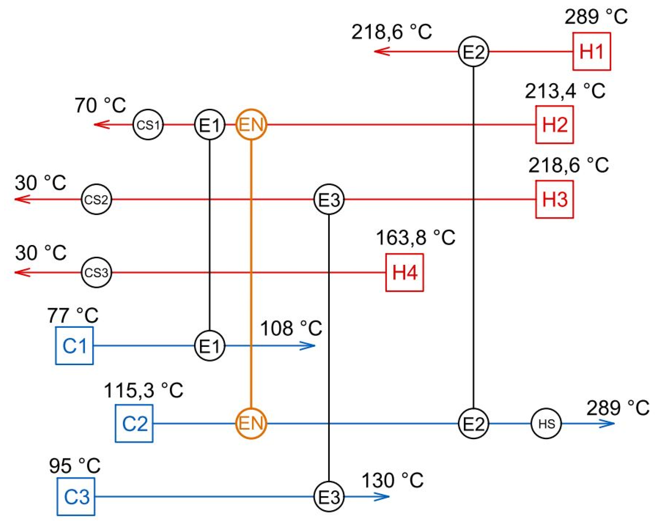
  • Stating desired retrofit targets and collecting input data about the process and its existing Heat Exchanger Network (process streams data extraction from a process scheme, further identification of hot and cold process streams, current hot and cold utility heat load, and existing heat exchanger performance and heat duties). Depicting the current HEN using the Grid Diagram (GD).
  • The EMAT (exchanger minimum approach temperature) value determination. It is a minimum allowable temperature approach of process media in the newly designed HEs creating new Utility Paths. The EMAT value evaluation is dependent on the existing HEN parameters and is discussed by Zhu and Asante [29].
Step 2: RI stage of HEN retrofit—identification of the new most beneficial Utility Path/s
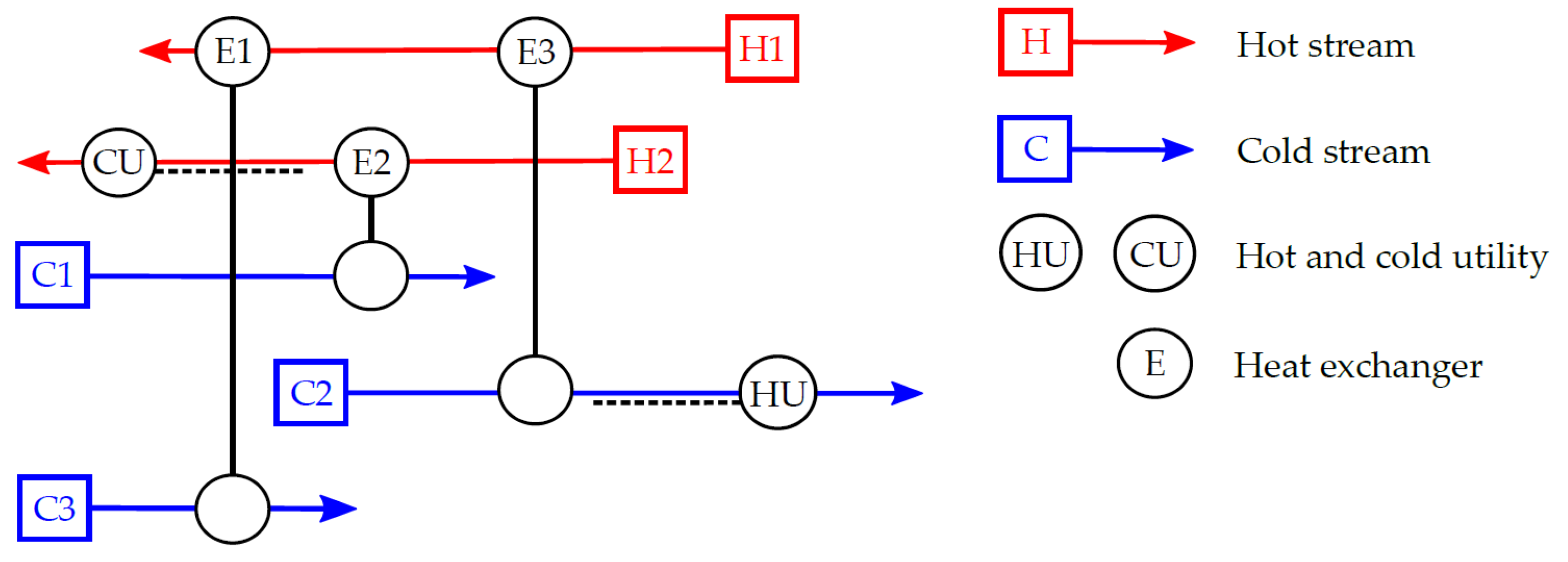
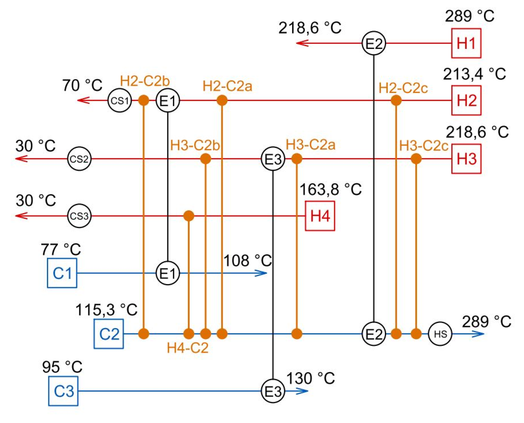
  • All thermodynamically feasible Utility Paths, thus the potential locations for the new HE insertion, are drawn to the GD of the current non-standard HEN. The obtained representation of feasible Utility Paths in GD is called the Retrofit Superstructure Grid Diagram (RSGD), which is a platform for the most efficient Utility Path identification. Only feasible matches are included in RSGD, which simplifies its structure and excludes unrealizable HEN modifications.
  • Every realizable Utility Path contained in RSGD is verified from the Maximum Heat Recovery Potential (Rmax) point of view using a linear programming (LP) model to the Network Pinch diagnosis. Specifically, there is an applied so-called Basic LP Model P1 for Identification of the Network Pinch published by Zhu and Asante [29]. This linear model allows finding Rmax (i.e., a suitable location for the new HE insertion) considering a specified EMAT value. Use of the linear model ensures finding the so-called global optimum solution, i.e., the optimal location for a new HE insertion is obtained, which is the main objective of this part of the developed method. Linear model implementation is also less difficult due to its simplicity in comparison with using the non-linear model. For the LP Model P1 application, any software enabling numerical programming can be used. In this work, the educational version of software Maple 2018 (Maplesoft, Waterloo, ON, Canada) [30] from the company Maplesoft is used, where the optimization package Simplex provides an appropriate numerical tool. The linear model consists of the process and thermal characteristics of the streams (as a flowrate and specific heat capacity), the heat balance of existing heat exchangers, and the EMAT value. The objective function is the maximization of the Rmax value described above.
  • When all the potential Utility Paths from the RSGD are assessed by the LP model, the obtained results are sorted to the so-called Retrofit Identification Table (RIT) from the most beneficial to the least beneficial Utility Path in terms of achievable Rmax. The main advantage of using RIT is the simultaneous profitability evaluation of each potential Utility Path, the location for a new HE insertion, and its heat duty.
  • The most beneficial Utility Path found in RIT (therefore with highest Rmax) is suitable for the new HE insertion. These results obtained in the RI stage are input data for the following (detail design) stage of the developed retrofit method.
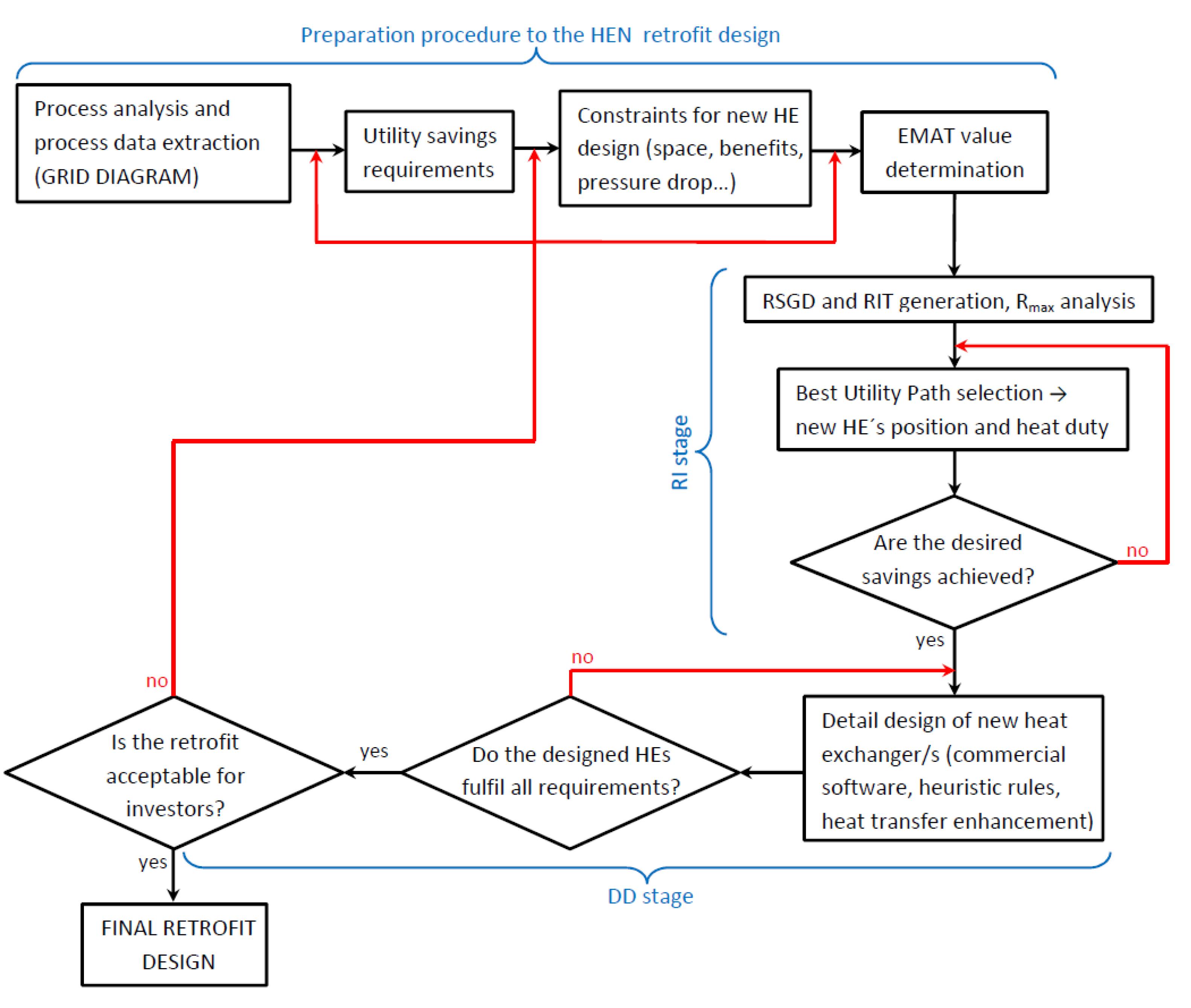
  • In case that the results of RI do not satisfy the required reduction of utility loads to the desired level, the RI stage is applied repeatedly, taking the most beneficial Utility Path from the previous search as a basis of the HEN topology for the next search, for finding the next most beneficial Utility Path (see Figure 3).
Step 3: Detail design (DD) stage of new heat exchanger/s which create/s the most beneficial Utility Path/s
The detailed design of new HEs at the positions localized in the RI stage is carried out by commercial software for heat exchanger design. In this study, the software HTRI was employed. For finding the optimal parameters of newly designed HE without knowledge of investment cost relations, we used the following heuristic rules based on the HE performance reassessment (Jiang et al. [23]).
  • The new HEs are of the same type, design, and size as adjacent exchangers operating with the same fluids. This ensures the purchase and maintenance cost minimization and the interchangeability of the exchangers and their parts.
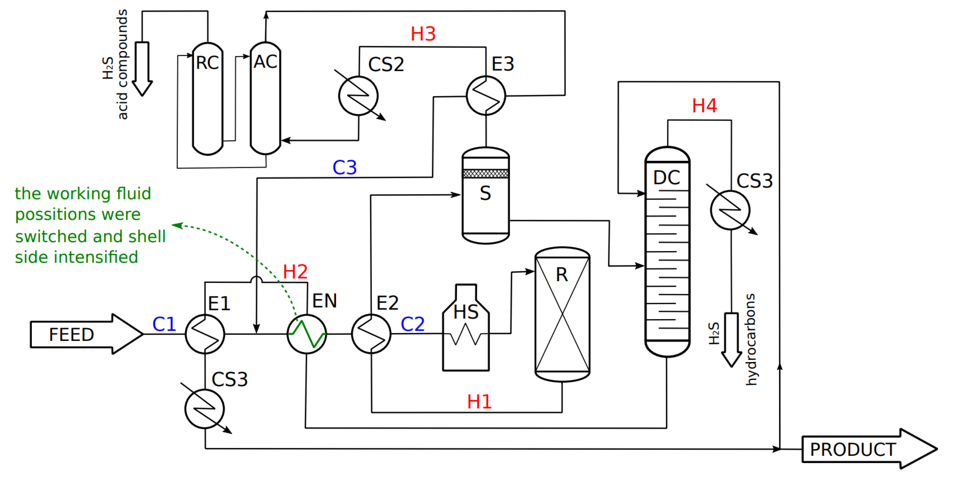
  • In case that the new HE does not reach the desired heat duty, try to switch the position of the working fluids in the exchanger, if possible.
  • If the desired heat duty is still not reached, the common and cheap technology for heat transfer enhancement may be implemented with respect to the set constraints (allowed pressure drop, etc.). Thus, the required HE performance can be accomplished with minimal investment cost.
  • Verify the final retrofit design and consult it with the client, respectively the process operator.
The described hybrid method is further applied to the case of the Heat Exchanger Network retrofit in the process of the hydrogenation of oil, where the current HEN does not contain any Utility Path.

3. Case Study

The developed hybrid method is now to be practically introduced by its application to a retrofit of the specific industrial process with a non-standard (i.e., not containing a Utility Path) Heat Exchanger Network; specifically, it is an industrial unit for the hydrogenation (or hydrotreating) of heavy petroleum products. The plant owner requires the hot utility demand reduction by at least 30% with minimal investment costs, and the maximum allowed pressure drop of each stream is 30 kPa.
The studied process is introduced with all key equipment including the current Heat Exchanger Network.

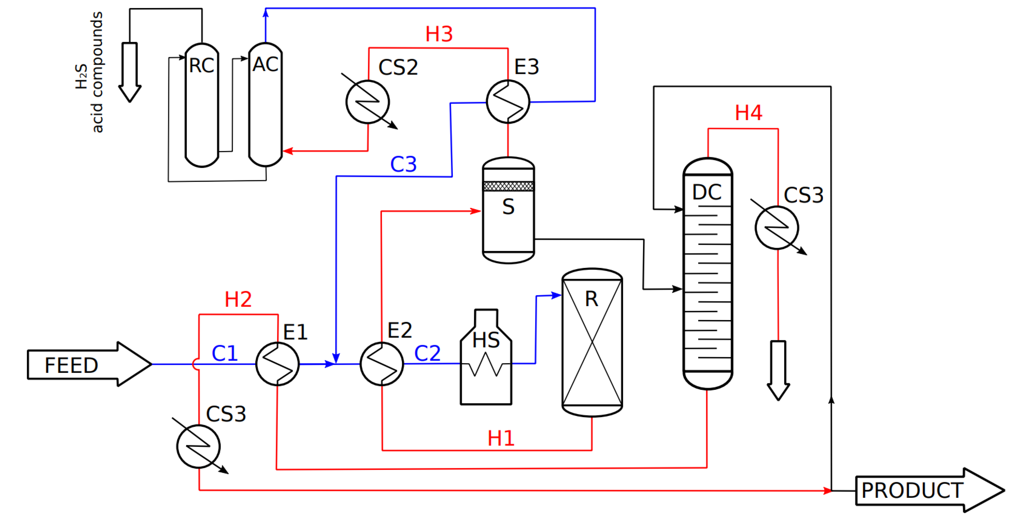
Description of the Studied Process

The hydrogenation process plant is used for the desulfurization of petroleum products. The process is illustrated in Figure 4, where the key equipment (reactor, separators, furnace, heat exchangers) is drawn black, hot process streams are red (H1–4), and cold process streams are blue (C1–3).
The feed stream (the oil fraction), as the stream C1, is heated up in the heat exchanger E1 by the hot process stream H2. Afterward, the feed stream is mixed with hydrogen (stream C3), and the resulting mixture (stream C2) is heated up in the exchanger E2 and in the process furnace to the temperature 289 °C and enters the reactor R, where hydrogenation reactions take place. The hot product from the reactor (stream H1) is used to preheat the feed and hydrogen mixture in exchanger E1 and then continues to the separator, where the so-called Hydrogen Gas, composed of the unreacted hydrogen, hydrogen sulfide, and acid compounds, is separated from the product stream. Hydrogen Gas (stream H3) is cooled down (in heat exchanger E3 and cooler CS2) and cleaned of the sulfur and acid compounds in the absorption unit, AC. The purified stream containing mostly hydrogen is then brought back, as a stream C3, to the feed stream entering the process.
The liquid product is brought from the separator to a distilation column (unit DC), where it is purified from the hydrogen sulfide and light hydrocarbons residuals (stream H4 cooled by cooler CS3). The obtained product (stream H2) is used to preheat feedstock (stream C1) in exchanger E1, cooled down in cooler CS1, and part of it is returned to the distilation column to increase the final product quality.

4. Results and Discussion

In this part of the presented paper, the developed method is applied to the intensification of the process described in the previous chapter following the calculation procedure of the developed method (see Materials and Methods).
First, the EMAT value is set. Then, the developed method is applied, and the process retrofit is performed to reduce energy demand to the required level while keeping the current production capacity. In the next part of the retrofit (RI stage), the RSGD is generated and the LP model (the model P1 [29]) is used to identify the most beneficial potential Utility Path to be introduced by a new HE insertion with required heat duty. Afterward, the following part (DD stage) of the retrofit is focused on the detail design and intensification of the new HE considering the specified restrictions (i.e., the allowed pressure drop of the process media).

4.1. Preparation Procedure to the HEN Retrofit Design

The preparation procedure to the HEN retrofit design includes in particular (i) defining the goals of the process retrofit, (ii) completing input data about the process and its existing Heat Exchanger Network (process streams data extraction from a process scheme, identification of hot and cold process streams, current hot and cold utility heat load, and existing heat exchangers performance and heat duties) including generation of the Grid Diagram (GD), and (iii) the EMAT value determination acceptable for existing heat exchangers retrofit as well as for the newly designed heat exchangers. The conclusions of these steps are as follows.
(i)
The requirements received by the plant owner imply that the retrofit of the hydrogenation process could be defined as the energy retrofit, which aims to reduce the hot utility demand (i.e., the process furnace fuel consumption) by at least 30% with minimal investment costs, while the process media pressure drop can exceed maximum 30 kPa for each.
(ii)
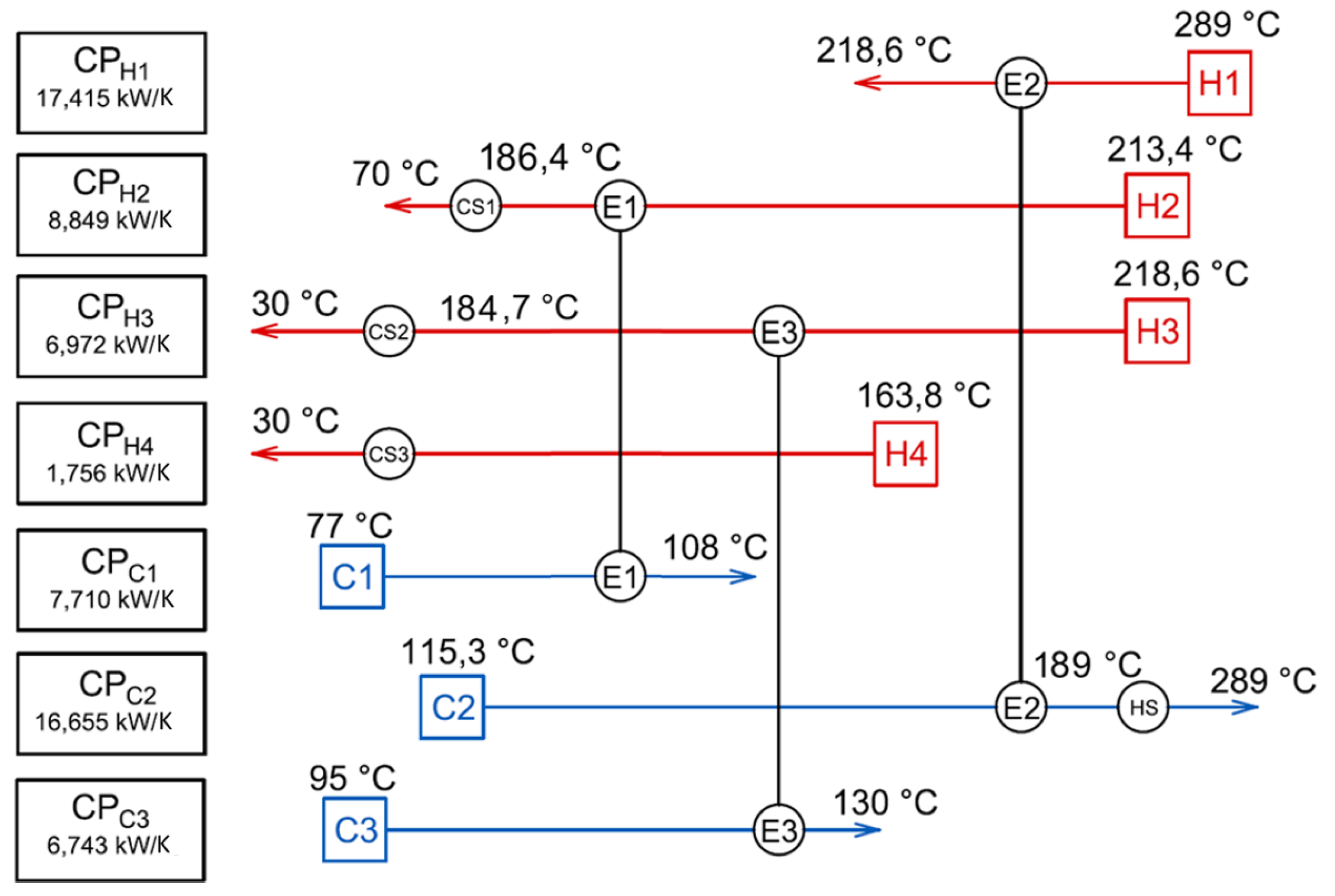
Within the process input data collection, the hot and cold streams, taking part in the process heat exchange, were identified, via Section 3. All key equipment was analyzed, including the heat exchangers forming the current HEN, whose main characteristics are summarized in Table 1. According to the collected data, the Grid Diagram was further generated and is illustrated in Figure 5. As it is observed in GD, the current HEN does not contain any Utility Path; therefore, it is defined as the non-standard HEN, and thus the developed retrofit method can be applied.
(iii)
The EMAT value determination adequate for the existing HEs retrofit as well as for the potential newly designed HEs was carried out according to the instruction provided in [29]. Individual EMAT values of the existing heat exchangers in the studied process range between approximately 88 and 109 °C. Taking into account a very high oversizing of the existing exchangers (see Table 1), the EMAT = 40 °C has been assessed as a practical and operationally easy to achieve value for the existing heat exchangers and also for any new units placed to the HEN of studied process. Additionally, the feasibility of meeting the required hot utility saving was verified by performing the standard targeting procedure (Klemeš et al. [31]). The maximum feasible hot utility saving for the obtained EMAT value is 52.3%, which is high above the client’s hot utility saving demand, which is 30%. However, reaching this significant savings would presumably lead to significant modifications of current HEN and thus high investment cost. As the investment cost minimization is required, a utility saving lower than 52.3% is assumed.

4.2. Retrofit Identification (RI Stage) of HEN–the Most Beneficial Utility Path Localization

The first step of the RI stage is RSGD generation, which is obtained from GD, where all thermodynamically feasible matches creating a new Utility Path (i.e., possible positions for the new heat exchangers insertion) are drawn. Only feasible matches are included in RSGD, which simplifies its structure and excludes unrealizable HEN modifications. The RSGD created for the studied oil hydrogenation process contains 7 potentially feasible Utility Paths and is illustrated in Figure 6.
The next step is focused on the Rmax evaluation of each Utility Path found in the RSGD. For this purpose, there was applied the Basic LP Model P1 for the Identification of Network Pinch published by Zhu and Asante [29]. This linear model allows finding Rmax (i.e., a suitable location for the new HE insertion) considering the specified EMAT value. Then, the results obtained by this model are sorted to the RIT in order from the most to the least beneficial (in terms of Rmax) Utility Path. RIT together with RSGD enables a very quick assessment of all feasible Utility Paths as well as the locations and heat duties of new heat exchangers creating the specific Utility Path. The basic results from RIT created for the studied oil hydrogenation process are summarized in Table 2.
From the RIT in Table 2, it is obvious that the most profitable Utility Path is in the position H2-C2a. By placing a new heat exchanger to this position, the hot utility demand will be reduced by about 30.8%, which meets the HEN retrofit target. Further, as it is observed in RIT, some Utility Paths (H2-C2c and H3-C2c) wouldn’t be beneficial, because they cannot be realized without breaking the EMAT value. RIT detailed information about the most convenient Utility Path (H2-C2a) related to the heat duty of specific HEs in modified HEN is in Table 3. The heat duties of the existing heat exchangers E1–3 remain the same as in the current operation, and the heat duty of the new heat exchanger (further EN) will be 514.1 kW.
As a result of the RI stage of the developed method for the retrofit of non-standard HENs applied to the case study, the most beneficial Utility Path was found and will be realized by insertion of the new heat exchanger EN with heat duty 514.1 kW. A final GD with the designed modifications of the current HEN is in Figure 7.

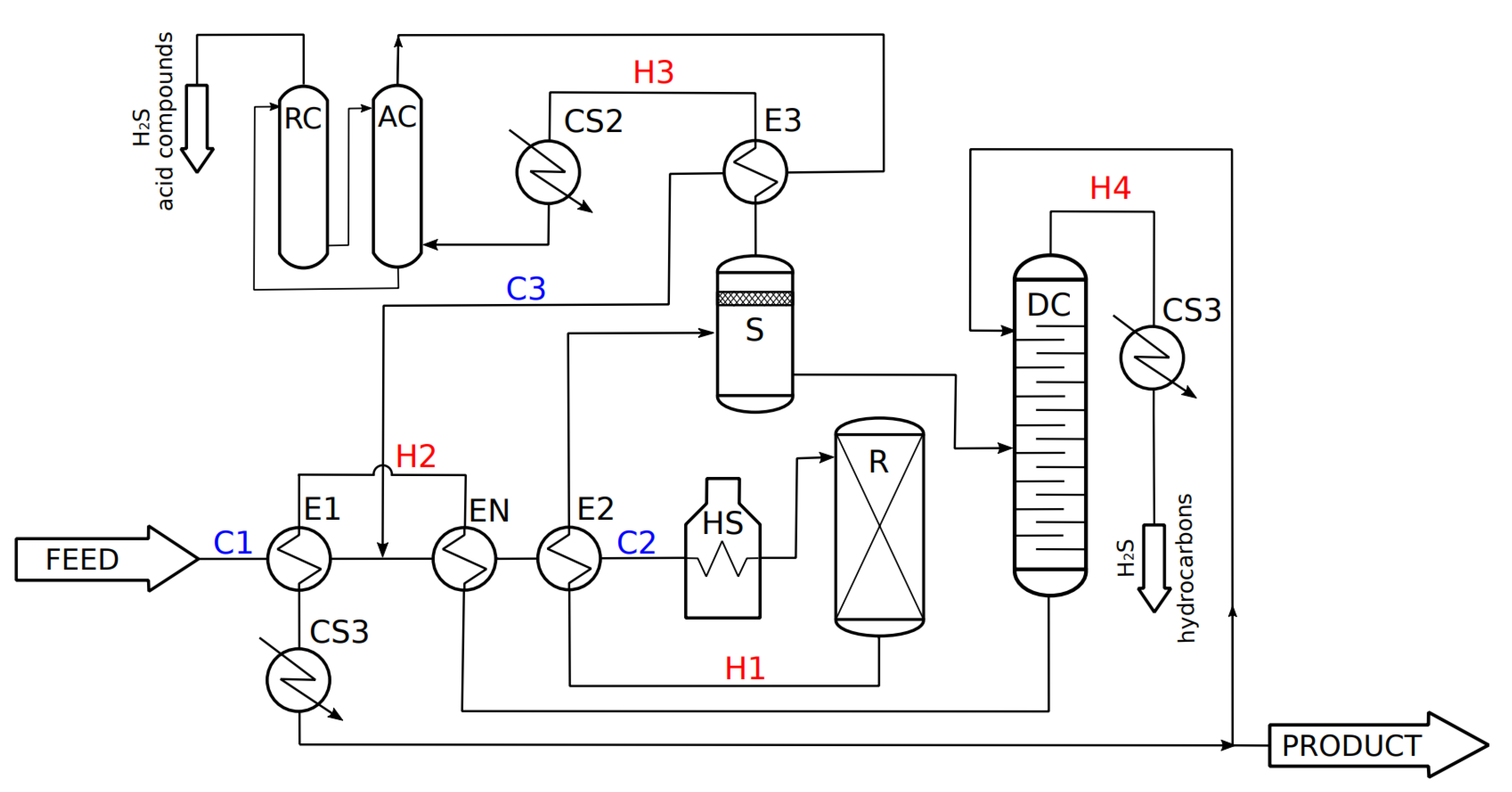
4.3. Detail Design (DD) Stage of the New Heat Exchanger (EN) Creating Most Beneficial Utility Path

The results of the RI stage are further used as input for the DD stage of the retrofit method procedure. First, the simulation scheme of the studied process was compiled, taking into account the results from the RI stage of the HEN retrofit. This scheme is illustrated in Figure 8.
Then, the energy and mass balance of the modified process with the EN exchanger was performed. For this purpose, we applied an educational version of software CHEMCAD (in the latest version CHEMCAD 7) from Chemstations, Inc. (Houston, TX, USA) [32]. According to this detailed simulation, the heat duty of EN is slightly higher than the heat duty calculated in the RI stage. The reason for this difference is that for the RI stage, the process stream data are extracted (in accordance with Pinch Analysis rules) from the process diagram with the so-called linearization on the safe side (see for example [22]), which means that the results obtained in the RI stage are more conservative than the real ones. The comparison of heat balance results for the heat exchanger EN obtained from the linear (or LP) model and detailed (nonlinear) simulation are summarized in Table 4.
The detailed heat balance of the process shows that the heat load of the heat exchanger EN at the position H2-C2a will reach 561.5 kW and hot utility savings of 33.7% (see Table 4), which is more than the results obtained in the RI stage, as stated above. Therefore, the client’s requirement for a hot utility reduction by at least 30% is fully met.
Then, the new heat exchanger EN is designed using software HTRI and heuristic rules described in the previous chapter. As the EN is localized in the process diagram (an also physically) next to the heat exchanger E2, the exchanger EN is therefore initially designed as the same type, size, and configuration to the exchanger E2 (see Table 1). The hot and cold fluid position is also similar, so the hot stream H2 is designed in the tube side and the cold stream C2 is designed in the shell side of the exchanger EN.
The next step of the DD stage is the rating simulation of exchanger EN. According to the results, the EN, with the same parameters as E2, is for the designed heat load heavily undersized (the negative overdesign 69.7%). However, the heat duty of the heat exchanger could be improved significantly by intensification technology implementation [33].
Following the developed procedure, the positions of working fluids were switched, i.e., the process stream C2 was placed to the tube side and H2 was placed to the shell side of the heat exchanger EN. The analysis of such modification was performed in software HTRI. The heat transfer coefficient on the tube side of the heat exchanger was decreased, while the heat transfer coefficient on the shell side was increased by the fluid switch. The shell side of the heat exchanger is a control side, i.e., the side with the lower heat transfer coefficient. However, this modification considerably increases the overall heat transfer coefficient and the value of undersizing is decreased from 69.7% to 43.8% (i.e., the negative overdesign is 43.8%). According to the DD stage procedure and following the developed heuristic rules, the heat transfer enhancement technology is to be applied to increase the heat transfer coefficient on the control side (shell side) of the heat exchanger. The heat transfer enhancement of the shell side acceptable for the client is the replacement of segmental baffles (placed in E2) by helical baffles. In order to maximize the heat transfer in EN and meet the pressure drop limit, the analysis in software HTRI was performed to obtain an optimal value of helical baffle inclination angle, which is 8°. This newly designed heat exchanger reaches the desired heat duty 561.5 kW and also meets allowed the pressure drop limit. The whole DD stage with selected parameters is summarized in Table 5.
The operating conditions of units E1 and E2 are affected by the insertion of heat exchanger EN—especially the temperature difference between the working media, which is decreased. Thus, it is necessary to verify whether the existing exchangers are able to cover the current heat load under the modified conditions. Both exchangers are strongly overdesigned (see Table 1) and according to the analysis, which was performed in order to predict their operating parameters under modified conditions, it was found out that both heat exchangers E1 and E2 are able to keep the current heat load, and therefore, their intensification or modification of any sort is not necessary.
By EN heat exchanger insertion, the heat duty demand of the studied process was reduced by 33.7%, which fully satisfies the retrofit requirements. The final process diagram of the energy retrofit is illustrated in Figure 9.

5. Conclusions

In this paper, a method was proposed for the systematic, efficient, and practical retrofit of a specific nonstandard kind of HENs not containing a Utility Path. The developed method can be classified as a hybrid two-stage method. The initial stage RI (the retrofit identification) allows finding the most beneficial Utility Path by the combination of Network Pinch principles and mathematical programming supported by two new efficient tools (for quick visualization of retrofit objectives and results): the Retrofit Superstructure Grid Diagram (RSTD) and Retrofit Identification Table (RIT). Following, the Detail Design (DD) stage is focused on the design of the newly added heat exchangers. In this stage, a standard commercial software for heat exchanger design is used in combination with several heuristic rules for cost-free investment and the cost minimization of a new heat exchanger, considering heat transfer enhancement within the available exchanger type, space, and fluids pressure drop constraints. The RI stage and DD stage are separate; however, due to the unique and specific combination of these two stages (shown on Figure 3 above), the presented method is systematic, straightforward, interactive, and practical to use. Generally, a two-step approach is also a proven and effective way for the retrofit of standard HENs [29]. From this point of view, our two-stage approach confirms this trend also for the retrofit of non-standard HENs. An illustrative industrial case study for the non-standard HEN retrofit of the oil hydrogenation process is involved to show the possibilities and advantages of our developed method. More than 30% energy savings of process hot utility is obtained by its application where the most beneficial Utility Path is identified in the RI stage and detailed design of the newly added heat exchanger (realizing this Utility Path) is performed in the DD stage of the method.
In summary, the main advantage of the proposed method is a straightforward, strongly practically oriented and relatively simple procedure for finding the suitable place in existing HEN to create the best possible Utility Path. This is ensured by the linear model implementation, which is suitable for finding the global optimum, i.e., the optimal place for new HE insertion. The detailed design of the new HE follows the proposed heuristic rules, which enable quick and efficient design and also provide a cost-free approach for the investment and maintenance cost minimization and HE interchangeability within the studied process. On the other hand, following the heuristic rules does not have to necessarily provide the best theoretically possible (or optimum) HE design, but it gives a highly practical HE design efficiently employing heat transfer enhancement possibilities together with the consideration of actual options (such as the overdesign) of existing HEs in the HEN. However, the optimum economic HE design, allowed by up-to-date sophisticated algorithms, such as Genetic Algorithm (GA), Particle Swarm Optimization (PSO), Imperialist Competitive Algorithm (ICA), Biogeography-Based Optimization (BBO), Cuckoo-Search-Algorithm (CSA), or Firefly Algorithm (FA), is implementable. Among these optimization algorithms, the FA seems to be the most beneficial for shell-and-tube HEs, as analyzed in [34]. Therefore, for those users who would need to solve the DD stage in the presented method in a highly sophisticated way, we recommend using just FA. In addition, our future research direction will be focused on the DD stage. However, our intention of development in this field will be primarily focused on maximum simplicity and practicality for the everyday use of process engineers.

Author Contributions

This publication has resulted from research performed by Z.J. and V.F. Both authors contributed directly to all aspects of the work. All authors have read and agreed to the published version of the manuscript.

Funding

This research was supported by the EU project Strategic Partnership for Environmental Technologies and Energy Production, funded as project No. CZ.02.1.01/0.0/0.0/16_026/0008413 by Czech Republic Operational Programme Research, Development and Education, Priority Axis 1: Strengthening capacity for high-quality research.

Conflicts of Interest

The authors declare no conflict of interest.

References

  1. Sreepathi, B.K.; Rangaiah, G.P. Review of heat exchanger network retrofitting methodologies and their applications. Ind. Eng Chem Res. 2014, 53, 11205–11220. [Google Scholar] [CrossRef]
  2. Hohman, E.C. Optimum Networks of Heat Exchange. Ph.D. Thesis, University of Southern California, Los Angeles, CA, USA, June 1971. [Google Scholar]
  3. Huang, F.; Elshout, R.V. Optimizing the heat recovery of crude units. Chem. Eng. Prog. 1976, 72, 68–72. [Google Scholar]
  4. Umeda, T.; Itoh, J.; Shiroko, K. Heat exchange system synthesis. Chem. Eng. Prog. 1978, 74, 70–76. [Google Scholar]
  5. Linnhoff, B.; Mason, D.R.; Wardle, I. Understanding heat exchanger networks. Comp. Chem. Eng. 1979, 3, 295–302. [Google Scholar] [CrossRef]
  6. Linnhoff, B.; Townsend, D.W.; Boland, D.; Hewitt, G.F.; Thomas, B.E.A.; Guy, A.R.; Marsland, R.H. A User Guide on Process Integration for the Efficient Use of Energy, 1st ed.; IChemE: London, UK, 1982. [Google Scholar]
  7. Tjoe, T.N.; Linnhoff, B. Using pinch technology for process retrofit. Chem. Eng. 1986, 93, 47–60. [Google Scholar]
  8. Carlsson, A.; Franck, P.A.; Berntsson, T. Design better heat exchanger network retrofits. Chem. Eng. Progr. U. S. 1993, 89, 87–96. [Google Scholar]
  9. Lakshmanan, R.; Bañares-Alcántara, R. A novel visualisation tool for heat exchanger network retrofit. Ind. Eng. Chem. Res. 1996, 35, 4507–4522. [Google Scholar] [CrossRef]
  10. Lakshmanan, R.; Bañares-Alcántara, R. Retrofit by inspection using thermodynamic process visualization. Comput. Chem. Eng. 1998, 22, 809–812. [Google Scholar] [CrossRef]
  11. Yong, J.Y.; Varbanov, P.S.; Klemeš, J.J. Heat exchanger network retrofit supported by extended Grid Diagram and heat path development. Appl. Therm. Eng. 2015, 89, 1033–1045. [Google Scholar] [CrossRef]
  12. Gadalla, M.A. A new graphical method for Pinch Analysis applications: Heat exchanger network retrofit and energy integration. Energy 2015, 81, 159–174. [Google Scholar] [CrossRef]
  13. Akpomiemie, M.O.; Smith, R. Cost-effective strategy for heat exchanger network retrofit. Energy 2018, 146, 82–97. [Google Scholar] [CrossRef] [Green Version]
  14. Grossmann, I.E. Mixed-integer nonlinear programming techniques for the synthesis of engineering systems. Res. Eng. Des. 1990, 1, 205–228. [Google Scholar] [CrossRef] [Green Version]
  15. Ciric, A.R.; Floudas, C.A. A comprehensive optimization model of the heat exchanger network retrofit problem. Heat Recover. Syst. CHP 1990, 10, 407–422. [Google Scholar] [CrossRef]
  16. Dolan, W.B.; Cummings, P.T.; Le Van, M.D. Algorithmic efficiency of simulated annealing for heat exchanger network design. Comput. Chem. Eng. 1990, 14, 1039–1050. [Google Scholar] [CrossRef]
  17. Yee, T.F.; Grossmann, I.E. A screening and optimization approach for the retrofit of heat-exchanger networks. Ind. Eng. Chem. Res. 1991, 30, 146–162. [Google Scholar] [CrossRef]
  18. López-Maldonado, L.A.; Ponce-Ortega, J.M.; Segovia-Hernández, J.G. Multiobjective synthesis of heat exchanger networks minimizing the total annual cost and the environmental impact. Appl. Therm. Eng. 2011, 31, 1099–1113. [Google Scholar] [CrossRef]
  19. Asante, N.D.; Zhu, X.X. An automated approach for heat exchanger network retrofit featuring minimal topology modifications. Comput. Chem. Eng. 1996, 20, 7–12. [Google Scholar] [CrossRef]
  20. Smith, R.; Jobson, M.; Chen, L. Recent development in the retrofit of heat exchanger networks. Appl. Therm. Eng. 2010, 30, 2281–2289. [Google Scholar] [CrossRef] [Green Version]
  21. Bakhtiari, B.; Bedard, S. Retrofitting heat exchanger networks using a modified Network Pinch approach. Appl. Therm. Eng. 2013, 51, 973–979. [Google Scholar] [CrossRef]
  22. Smith, R. Chemical Process Design and Integration; John Wiley & Sons: Hoboken, NJ, USA, 2016. [Google Scholar]
  23. Jiang, N.; Han, W.; Guo, F.; Yu, H.; Xu, Y.; Mao, N. A novel heat exchanger network retrofit approach based on performance reassessment. Energy Convers. Manag. 2018, 177, 477–492. [Google Scholar] [CrossRef]
  24. Rathjens, M.; Fieg, G. Design of Cost-Optimal Heat Exchanger Networks Considering Individual, Match-Dependent Cost Functions. Chem. Eng. Trans. 2018, 70, 601–606. [Google Scholar]
  25. Lai, Y.Q.; Wan Alwi, S.R.; Manan, Z.A. Heat Exchanger Network Retrofit Considering Physical Distance, Pressure Drop and Available Equipment Space. Chem. Eng. Trans. 2019, 76, 367–372. [Google Scholar]
  26. Linnhoff, B.; Hindmarsh, E. The pinch design method for heat exchanger networks. Chem. Eng. Sci. 1983, 38, 745–763. [Google Scholar] [CrossRef]
  27. Varbanov, P.S.; Klemeš, J.J. Rules for path construction for HENs debottlenecking. Appl. Therm. Eng. 2000, 20, 1409–1420. [Google Scholar] [CrossRef]
  28. HTRI. Available online: https://www.htri.net (accessed on 12 December 2019).
  29. Zhu, X.X.; Asante, N.D.K. Diagnosis and Optimization Approach for Heat Exchanger Network Retrofit. AIChE J. 1999, 45, 1488–1503. [Google Scholar] [CrossRef]
  30. Maple. Available online: https://www.maplesoft.com (accessed on 15 May 2020).
  31. Klemeš, J.J.; Varbanov, P.S.; Wan Alwi, S.R.; Manan, Z.A. Process. Integration and Intensification, Saving Energy, Water and Resources, 2nd ed.; De Gruyter: Berlin, Germany, 2018. [Google Scholar]
  32. Chemstations. Available online: http://www.chemstations.com (accessed on 12 December 2019).
  33. Zhu, X.X.; Zanfir, M.; Klemeš, J. Heat transfer enhancement for heat exchanger network retrofit. Heat Transf. Eng. 2000, 21, 7–18. [Google Scholar]
  34. Mohanty, D.K. Application of firefly algorithm for design optimization of a shell and tube heat exchanger from economic point of view. Int. J. Therm. Sci. 2016, 102, 228–238. [Google Scholar] [CrossRef]
Figure 1. HEN containing a Utility Path.
Energies 13 02711 g001
Figure 2. Heat Exchanger Network (HEN) not containing a Utility Path.
Energies 13 02711 g002
Figure 3. The developed procedure algorithm.
Energies 13 02711 g003
Figure 4. Current industrial plant for the hydrogenation of oil.
Energies 13 02711 g004
Figure 5. Grid Diagram of the existing HEN.
Energies 13 02711 g005
Figure 6. The Retrofit Superstructure Grid Diagram (RSGD) of the studied process.
Energies 13 02711 g006
Figure 7. Modified Grid Diagram (GD) of the studied process.
Energies 13 02711 g007
Figure 8. The modified process scheme with the inserted new heat exchanger (EN).
Energies 13 02711 g008
Figure 9. Process diagram of the energy retrofit obtained from the DD stage.
Energies 13 02711 g009
Table 1. The geometric and process characteristics of HEs employed in the current HEN.
Heat ExchangerUnitE1E2E3HUCUtot 1
Geometry
TEMA typeAESAESAES
Number of shells in series-parallel1-11-21-1
Number of shell-tube passes1-41-41-4
Tube lengthm5.566
Tube outer diameter/thicknessmm25/2.525/2.525/2.5
Tube layout angle°303030
Tube pitchmm323232
Number of tubes808080
Shell outside diametermm440440440
Baffle heightmm360420420
Baffle spacingmm150240240
Number of baffles302020
Process data
Heat dutykW2391 22623616672344 1
Heat transfer aream234.575.437.7
Shell side streamC1C2C3
Tube side streamH2H1H3
Shell side heat transfer coeff.W/m2K303.2497.4198.7
Tube side heat transfer coeff.W/m2K382.71709.52531.1
Mean temperature difference°C10789.286.8
Overdesign 2%119.667.476.3
1 The value of CUtot (total cold utility) is given as a sum of the coolers CS1–3 heat duties. 2 To obtain the overdesign of the heat exchangers E1–3, the software HTRI was used.
Table 2. Retrofit Identification Table (RIT) of the studied process.
Utility PathRmax [kW]HU [kW] 1HU Savings [%]CU [kW] 1CU Savings [%]
H2-C2a2215.21152.830.81829.721.9
H3-C2a2039.91328.120.32004.914.5
H2-C2b1976.11391.816.52068.711.7
H3-C2b1906.41461.612.32138.58.8
H4-C21716.01716.00.92328.80.6
H2-C2cRequired value of EMAT is not achievable in this Utility Path
H3-C2cRequired value of EMAT is not achievable in this Utility Path
1 HU and CU is the hot and cold utility total heat duty related to the specific Utility Path.
Table 3. Detailed information about the most beneficial Utility Path.
E1 [kW]E2 [kW]E3 [kW]EN [kW]Rmax [kW]HU Savings [%]CU Savings [%]
2391226236514.12215.230.821.9
Table 4. The heat duty results of exchanger EN obtained from the Retrofit Identification (RI) stage and Detail Design (DD) stage.
Retrofit Stage (Model)Duty of EN [kW]HU [kW]HU Savings [%]
RI stage (LP model)514.11152.830.8
DD stage (nonlinear simulation)561.51105.433.7
Table 5. The EN heat exchanger rating development in the DD stage.
UnitEN Parameters Similar to E2Working Fluid SwitchWorking Fluid Switch + Intensification
Heat duty[kW]561.5561.5561.5
Heat transfer area[m2]75.475.475.4
Shell side heat trans. coeff.[W/m2K]241.28119.33292.9
Tube side heat trans. coeff.[W/m2K]88.111395.51395.5
Overdesign[%]−69.69−43.79+9.86

