Article

Multiparameter and Multiobjective Optimization Design Based on Orthogonal Method for Mixed Flow Fan

1
State Key Laboratory of Hydroscience and Engineering, Department of Energy and Power Engineering, Tsinghua University, Beijing 100084, China
2
College of Mechanical and Electronic Engineering, Shandong University of Science and Technology, Qingdao 266590, China
*
Author to whom correspondence should be addressed.
Energies 2020, 13(11), 2819; https://doi.org/10.3390/en13112819
Submission received: 2 May 2020 / Revised: 26 May 2020 / Accepted: 27 May 2020 / Published: 2 June 2020

Abstract

:
Optimization design of an impeller is critical for the energy performance of a fan. This paper takes the promotion of fan efficiency and pressure rise as the optimization objectives to carry out multiparameter and multiobjective optimization research. Firstly, an experimental test bench is built to measure the energy performance of the original fan and verify the accuracy of the numerical method. Then, the hub outlet angle of impeller β1, the impeller outlet angle increment Δβ1, the wrap angle φ, the hub outlet angle of diffuser β2, and the diffuser outlet angle increment Δβ2 are set as the optimal parameters to conduct orthogonal optimal design. The results show that the efficiency of the optimal fan increases by 11.71%, and the pressure rise increases by 50.15%. The pressure and velocity distributions in an optimal fan are uniform, the internal flow separation is weakened, and the influence of tip leakage flow is reduced, which makes for the improvement of energy performance for the fan.

1. Introduction

As the fan is widely applied in national defense construction and industrial production, it plays a significant role in the national economy and daily life [1]. However, the efficiency of the fan is relatively low, resulting in a huge waste of energy. Therefore, the investigation into fan optimization is of great significance for energy conservation, emission reduction and the improvement of energy allocation.
Due to the complicated geometry of the fan, the gas flow characteristics and internal mechanism is complex. There are multiplex phenomena such as flow separation and vortex loss [2,3], which relates to the performance and efficiency of the fluid machinery. In order to promote the efficiency, it is necessary to study the flow characteristics and structure optimization. As multiple structural parameters need to be considered for the fan design and each parameter has a certain value range, which has different influence degrees on the aerodynamic performance of the fan.
In terms of experimental research, advance technology is used to observe the internal flow pattern of the fan. Comparing the flow field distribution under different design parameters, optimization for the aerodynamic performance is realized. The jet phenomenon in the impeller flow channel is experimentally observed [4], and the results reveal that the Reynolds number and the rotational speed have an important effect on the instability and uniformity of flow field. Later, hot-wire anemometer is adopted to measure the internal flow field of the fan [5], and the smoke visualization technology is chosen to observe the gas flow trajectory under different inlet conditions [6], so as to elaborate on the gas flow pattern. The five-hole probe technology can also be used to investigate the flow field at the impeller inlet and outlet under different operating conditions [7]. The study finds that the backflow phenomenon still exists in the flow channel even under design conditions, which affects the aerodynamic performance. Meanwhile, empirical formula [8] is put forward to reveal the relationship between fan noise and impeller design parameters through experimental measurements, and studies the effects of blade number, chord length and blade inclination on the wake width. On this basis, the relevance between fan frequency and the blade number is summarized [9]. The research results indicate that the design parameters of the impeller have an important influence on the aerodynamic performance of the fan. Zhou et al. [10] proposes a relationship between the blade trailing edge thickness and the energy characteristics of the fan through experiments. The research results demonstrate that the high-pressure region is enlarged with blade thickness. However, the diffusion of the trailing edge is poor at the same time, which intensifies the energy dissipation.
For numerical simulation, it is usually used as the optimal approach to evaluate the energy performance and internal flow field. Numerical simulation results can illustrate the eccentric vortex motion of airfoil blades [11] and present that the inclination angle plays an important part in the change of vortex size and aerodynamic performance. The change in the impeller wrap angle has been numerically found to promote the efficiency of the fan [12]. Lin et al. [13] selected the NACA4412 airfoil as the basis for blade design, and the fan performance has been improved by adjusting the blade inlet and outlet angle. The influence of the blade inlet angle at 25–36 degrees on the flow field of the fan has been explored [14], and the results demonstrate that the performance of the fan is promoted by 6% when the blade inlet angle is 27 degrees. In addition, the optimal fan has leakage reduction of 2.79% and 3.6% at the tip clearance of 2 and 2.5 mm, respectively. Studies about the influence of blade thickness on the flow characteristics of the fan have been analyzed [15]; the research results reveal that the efficiency is decreased with thicker blades, but the efficient working range becomes wider. On this basis, the mutual effects of the blade number, the outlet angle, and the diameter ratio of the impeller on the fan performance are comprehensively considered through numerical calculations [16]. The results indicate that the fan exhibits significant differences among different structure combinations under lower operating pressures.
For design optimization, plenty of optimization models and methods have been employed to conduct optimization research about the aerodynamic performance of the fan based on the influence of structural parameters. The hybrid multiobjective optimization method is adopted to perform numerical calculations combined with response surface model [17]. The proposed optimal structure effectively promotes the efficiency of the fan. The fan design with particle swarm algorithm realizes the improvement of the total pressure and efficiency [18]. The methods of inverse problem design [19], genetic algorithm [20] and Oseen vortex method [21] have also been used to realize the structure optimization. Choosing blade number and the outlet angle as optimization parameters and the fan efficiency as the optimization target [22], the final scheme is to increase the blade number by two and reduce the outlet angle by 0.5 degrees. The interpolation simulated annealing algorithm is applied to the fan optimization [23], and the results indicate that the pressure rise has also been promoted while satisfying the assumed efficiency. Hybrid multiobjective evolutionary algorithm was developed [24] with six variables related to the blade inclination angle and blade profile, and the efficiency of the fan can be improved and the torque is reduced through the multiobjective optimization process. Chen et al. [25] realized the optimization research with blade number and blade stagger angle through orthogonal experiments, and found that the blade stagger angle has the greatest effect. After the optimization, the flow of the fan was increased by 0.108 kg/s, and it was experimentally verified. Orthogonal experiment is also employed to study impeller optimization [26]. The inlet width, outlet width, blade installation angle, and impeller diameter were selected as optimization parameters, and flow rate was selected as the optimization target. Combined with the range and variance analysis, the optimal combination of impellers was obtained, and the aerodynamic performance of the fan was significantly improved.
The aerodynamic performance of the fan with different structural parameters has been studied through experimental research and numerical simulation in the above literature review. On this basis, different optimization algorithms are applied to the fan design, but with various optimization goals. Furthermore, now researches mainly focus on single-target optimization studies, while multiparameter and multiobjective optimization studies on the fan are relatively rare.
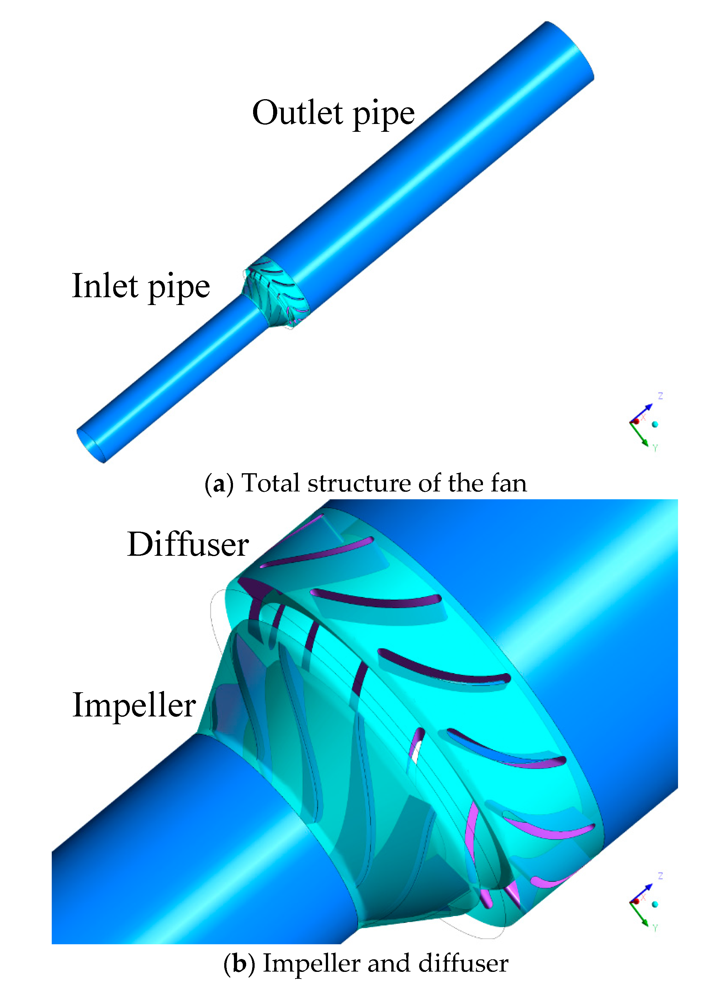
In this paper, investigations on the multiparameter and multiobjective optimization design of the fan are conducted. The hub outlet angle of impeller β1, the impeller outlet angle increment Δβ1, the impeller wrap angle φ, the hub outlet angle of diffuser β2, and the diffuser outlet angle increment Δβ2 are set as optimal parameters, and the pressure rise and efficiency are chosen as optimal objectives. With the conduction of orthogonal optimization design, the optimal fan is obtained. The influence degree of geometric parameters on the aerodynamic performance are studied, the optimal design scheme is obtained, and the internal flow mechanism is explored.

2. Physical Model and Computational Mesh

2.1. Physical Model of the Fan

In this paper, the fan is constructed with modeling software BladeGen (ANSYS Inc., Pittsburgh, PA, USA), and Table 1 presents the structural parameters of the fan.
Figure 1 shows the geometric structure of the fan, which mainly includes the inlet pipe, outlet pipe, impeller, and diffuser. In order to ensure the stability of the numerical calculation, equal-diameter inlet pipe and outlet pipe are added. The fan in the present work is a mix-flow fan with rated flow rate of 18 L/s and rated power of 500 W, and it is manufactured by Tsinghua University.

2.2. Computational Mesh of the Fan

In this paper, ICEM 17.0 (ANSYS Inc., Pittsburgh, PA, USA) and Turbogrid 17.0 (ANSYS Inc., Pittsburgh, PA, USA) are employed to generate the structured mesh of each component [27], and grid encryption is performed at the junction of the impeller blade and hub, and at the junction of the diffuser blade and hub. The mesh generation and mesh details of the impeller and diffuser are shown in Figure 2a,b.

3. Numerical Method and Setting

3.1. Numerical Method

In this paper, the computational fluid dynamics software CFX 17.0 (ANSYS Inc., Pittsburgh, PA, USA) is adopted for numerical simulation of the fan [28]. The SST k-ω turbulence model is chosen to solve the three dimensional time-averaged Navier–Stokes equation, and the model constants are given as β’ = 0.09, α = 5/9, β = 0.075, σk = 2 and σω = 2. The impeller is set as the rotating domain; the inlet pipe, diffuser and outlet pipe are set as static domains. The connection method between the impeller and the diffuser is connected with frozen rotor technology.

3.2. Boundary Conditions

According to the numerical method in Section 3.1, the boundary conditions for calculations [29] are shown in Table 2.

3.3. Mesh Independence Verification

It is important to choose a reasonable mesh for numerical simulation, which can save time and computing resources with the premise of ensuring calculation accuracy. Therefore, this paper uses five groups of mesh to conduct the grid independence test [30]. The mesh number distribution of each component is presented as follows, and the mesh independence verification obtained is shown in Table 3.
The final number of selected mesh is 99,900 for inlet pipe; 1,625,886 for impellers; 940,401 for diffuser; 104,400 for outlet pipe; and the total number is 2,770,587. In addition, the average value of y+ on the impeller blade is less than 5.

3.4. Simulation Validation

In order to verify the accuracy of the numerical method, a test bench and fan are set up for experimental research, as shown in Figure 3. The experimental research is carried out under a temperature of 25°, pressure of 1 atm, and relative humidity of 50%. The fluid medium is air with a density of 1.185 kg/m3 and viscosity of 18.1 Pa∙s.
Figure 4 presents a comparison between the numerical calculations and the experimental results. As can be seen in Figure 4, the red curve is the numerical simulations, and the black curve stands for the experimental measurement results. The average error between the numerical and experimental results is 2.84%, which verifies the accuracy of the numerical method.

4. Optimization Research of the Fan

4.1. Structural Optimization Based on Orthogonal Method

In this paper, the orthogonal method is applied in fan optimization. Selecting representative points and the results of comprehensive response can be obtained through a small group of experiments. The characteristics of orthogonal method are that the number of experiments is small, while the conclusions are reliable [31]. Based on the experimental study and numerical research, this paper selects the following five parameters and four levels for orthogonal method optimization. The five parameters are the hub outlet angle of impeller β1, the impeller outlet angle increment Δβ1, the impeller wrap angle φ, the hub outlet angle of diffuser β2, and the diffuser outlet angle increment Δβ2. The optimization goals are the efficiency and the pressure rise of the fan.
The expression of pressure rise is as follows [28]:
P R = P i n l e t P o u t l e t
where P R is pressure rise, P i n l e t is inlet pressure and P o u t l e t is outlet pressure.
The expression of efficiency is as follows:
η = P R Q / M Ω
where η is the fan efficiency, Q is the flow rate, M is the torque of impeller, and Ω is the angular velocity.
The optimization scheme based on orthogonal method is shown in Table 4.
According to the orthogonal Table 5, 16 groups of orthogonal experiments are designed and the calculation results are performed as follows.

4.2. Analysis of Orthogonal Experiments

According to the orthogonal experiments in Section 4.1, the range analysis of the fan efficiency and pressure rise is performed with the following expression [31]:
K i = 1 n η i
R = max ( K 1 , K 2 , K 3 , K 4 ) min ( K 1 , K 2 , K 3 , K 4 )
where η i is the efficiency of each orthogonal experiment, K i is the sum of η i , and R stands for the range. The results are shown in Table 6 and Table 7.
In order to simultaneously consider the promotion of fan efficiency and pressure rise, this paper conducts a multiobjective optimization study and defines the variable F for range analysis. F can be calculated by formula (5) [31]:
F = λ 1 Δ P R ¯ + λ 2 η ¯
where Δ P R ¯ and η ¯ are calculated by formula (6) and formula (7), respectively.
Δ P R ¯ = Δ P R i Δ P R min Δ P R max Δ P R min
η ¯ = η i η min η max η min
As for multiobjective optimization research, different weight coefficients need to be given to the optimization goals. In this paper, the weight of the efficiency λ2 is taken as 0.8 since the fan efficiency is the principal object to be considered, and the weight of pressure rise λ1 is taken as 0.2. Range analysis is performed according to the value of F, and the new range analysis is shown in Table 8.
The ranking of the impact degree for the five factors is the impeller wrap angle φ, the hub outlet angle of diffuser β2, the hub outlet angle of impeller β1, the impeller outlet angle increment Δβ1, and the diffuser outlet angle increment Δβ2.
Therefore, considering comprehensively increasing the efficiency and pressure rise of the fan, the impact degree of the impeller wrap angle φ is the largest, followed by the hub outlet angle of diffuser β2, the hub outlet angle of impeller β1, the impeller outlet angle increment Δβ1, and the diffuser outlet angle increment Δβ2. Finally, the optimization parameters are selected as follows: The hub outlet angle of impeller β1 is 50 degrees, the impeller outlet angle increment Δβ1 is 8 degrees, the impeller wrap angle φ is 60 degrees, the hub outlet angle of diffuser β2 is 80 degrees, and the diffuser outlet angle increment Δβ2 is 8 degrees.

4.3. Performance Comparison

According to the orthogonal experiments in Section 4.2, the optimal structure of the fan is obtained. The efficiency of original fan is 41.21%, while the efficiency of optimal fan is 52.92%, which is improved by 11.71%. Furthermore, the pressure rise of original fan is 7152 Pa, while the pressure rise of the optimal fan is 10,739 Pa, which is promoted by 50.15%.

5. Result and Discussion

5.1. Simulation Result of Pressure

Figure 5 demonstrates the pressure distribution of the pressure side in the original and optimal fan. It can be seen from the figure that the pressure gradually decreases from the leading edge to the trailing edge of the blade. This is because the air flows from the inlet to the impeller and impacts the leading edge, causing the generation of local high-pressure region. It is also displayed that the pressure gradually increases from the bottom to the top of the blade, because the interaction force between the blade and the airflow increases with the peripheral speed. The pressure change on pressure side is more obvious from 0.8Qd to 1.2Qd. Compared with the original fan, the pressure distribution in the optimal fan is uniform, the local high-pressure region is reduced, and the pressure gradient is smaller, which indicates that the airflow is smoother in the passage.
Figure 6 illustrates the pressure distribution of the suction side in the impeller. It can be seen from the figure that local high-pressure regions exists at the leading edge in the original fan, and the area becomes more obvious as the flow rate increases. While the pressure distribution is more uniform within the optimal fan, and the flow separation does not easily occur as the pressure gradient is smaller, which is in line with the design expectations.

5.2. Simulation Result of Velocity

It can be inferred from Figure 5 and Figure 6 that the pressure on the pressure side is higher than that on the suction side, and the local high-pressure region exists at the leading edge of the blade. Due to the large pressure difference at the leading edge and the existence of tip clearance, the gas velocity is relatively large and the flow pattern is more complicated. Therefore, the velocity distribution of different spans under the design flow rate are compared.
As for the optimal fan in Figure 7, the flow patterns at different spans are smoother than that in the original fan. It can be seen at span 0.1 that flow pattern at the inlet of optimal fan is more even, indicating that the flow condition has been improved. As shown at span 0.5, the pressure gradient inside the optimal fan is smaller. Furthermore, there are no turbulent vortices that occurred in the flow channel, and no obvious flow separation phenomenon exists in the impeller, indicating that the flow state is ideal. As described at span 0.9, the large vortex area appeared in the original fan with irregular distribution. However, the vortex area is significantly reduced and the flow velocity is relatively smooth within the optimal fan. Figure 7 confirms that the optimal fan exhibits better aerodynamic performance.

5.3. Simulation Result of Tip Leakage Flow

Since the pressure on the pressure side of the blade is higher than that on the suction side, the airflow on the pressure side will flow through the tip clearance between the blade and shroud under the effect of pressure difference, resulting in the occurrence of tip leakage flow [32,33,34]. In addition, the existence of the tip leakage flow will affect the flow stability of the mainstream in the flow channel. Therefore, the impact of the tip leakage flow is expected to be reduced in the optimal fan.
Figure 8 shows the velocity distribution of the tip clearance area near the leading edge of the blade. As for the original fan under different flow conditions, the tip leakage vortex is located at the top of the suction side. With the decrease of flow rate, the range of the leakage vortex gradually spreads to the hub along the radial direction, and the countercurrent area expands, which in turn affects the mainstream. While it can be seen that the leakage vortex dose not diffuse to the flow channel in the radial direction for the optimal fan, therefore, less influence is added on the mainstream.
As shown in Figure 9, the streamline near the impeller inlet expands to the flow channel and blends with the mainstream for the original fan under a flow rate of 0.8Qd. While the streamline near the impeller inlet is uniform for the optimal fan and the streamline expands along the tip clearance with regular distribution. When the flow rate increases to 1.0Qd, the streamline near the impeller inlet has a significant mixing effect with the mainstream for the original fan, while the distribution in the optimal fan is smooth. As the flow rate changes to 1.2Qd, the streamline expands into the next stage along the tip clearance for the original fan, and the flow velocity is faster. While the streamline distribution in optimal fan is still even in the current and next passage. It can be inferred that the optimal fan had a certain ability in the suppression of the tip leakage flow, which creates small impact on the flow stability of the impeller.

6. Conclusions

In this paper, the numerical solving method of the Reynolds time-averaged Navier–Stokes equation is adopted to investigate the flow characteristics and internal flow field of the fan. Comparing with the experimental results, the accuracy of the numerical method is verified. On this basis, the orthogonal method is employed to conduct the multiparameter and multiobjective optimization of the fan to improve the energy performance of the fan. The main work can be concluded as follows.
(1)
An experimental test bench is set up for the measurement of the energy performance. Then the numerical calculations are compared with experimental results to verify the accuracy of the numerical method.
(2)
Five important parameters and two optimization targets are set, and the orthogonal method is adopted for the optimization design of a fan. The influence degree of geometric parameters on the energy performance of the fan is obtained, and then an optimization scheme is proposed.
(3)
The results show that the efficiency of the optimal fan increases by 11.71%, and the pressure rise increases by 50.15%. The internal flow separation phenomenon in optimal fan is weakened, and the impact of the tip leakage flow is reduced.

Author Contributions

H.F., J.Z., W.Z. and B.L. proposed the method, H.F., J.Z., W.Z. and B.L. completed the numerical simulations, H.F., J.Z., W.Z. and B.L. analyzed the data, H.F., J.Z., W.Z. and B.L. wrote the paper. All authors have read and agreed to the published version of the manuscript.

Funding

This work has been funded by the National Natural Science Foundation of China [51879140].

Acknowledgments

This work has been supported by the National Natural Science Foundation of China [51879140].

Conflicts of Interest

The authors declare no conflict of interest.

Nomenclature

List of Symbols
β1Hub outlet angle of impeller
Δβ1Impeller outlet angle increment
φImpeller wrap angle
β2Hub outlet angle of diffuser
Δβ2Diffuser outlet angle increment
PRPressure rise
PinletInlet pressure
PoutletOutlet pressure
ηFan efficiency
QFlow rate
QdRated flow rate
MTorque of impeller
Ω Angular velocity
ηiEfficiency of each orthogonal experiment
KiThe sum of ηi
RRange

References

  1. Zhu, L.; Jin, Y.; Li, Y.; Jin, Y.; Wang, Y.; Zhang, L. Numerical and experimental study on aerodynamic performance of small axial flow fan with splitter blades. J. Therm. Sci. 2013, 22, 333–339. [Google Scholar] [CrossRef]
  2. Liu, M.; Tan, L.; Cao, S. Cavitation–Vortex–Turbulence Interaction and One-Dimensional Model Prediction of Pressure for Hydrofoil ALE15 by Large Eddy Simulation. J. Fluids Eng. 2018, 141, 021103. [Google Scholar] [CrossRef]
  3. Sun, W.; Tan, L. Cavitation-Vortex-Pressure Fluctuation Interaction in a Centrifugal Pump Using Bubble Rotation Modified Cavitation Model Under Partial Load. J. Fluids Eng. 2020, 142, 051206. [Google Scholar] [CrossRef]
  4. Fowler, H.S. The Distribution and Stability of Flow in a Rotating Channel. J. Eng. Power 1968, 90, 229–235. [Google Scholar] [CrossRef]
  5. Fowler, H.S. Aerodynamic Tests on a Centrifugal Fan Impeller Model with Swept-Back Blades; National Research Council Canada: Ottawa, ON, Canada, 1971. [Google Scholar]
  6. Fowler, H.S. Comparison of Thin Plate and Thick Aerofoil Blades in a Centrifugal Fan; National Research Council Canada: Ottawa, ON, Canada, 1971. [Google Scholar]
  7. Kind, R.J.; Tobin, M.G. Flow in a Centrifugal Fan of the Squirrel-Cage Type. J. Turbomach. 1990, 112, 84–90. [Google Scholar] [CrossRef]
  8. Fukano, T.; Kodama, Y.; Takamatsu, Y. Noise generated by low pressure axial flow fans, II: Effects of number of blades, chord length and camber of blade. J. Sound Vib. 1977, 50, 75–88. [Google Scholar] [CrossRef]
  9. Fukano, T.; Kodama, Y.; Takamatsu, Y. Noise generated by low pressure axial flow fans, III: Effects of rotational frequency, blade thickness and outer blade profile. J. Sound Vib. 1978, 56, 261–277. [Google Scholar] [CrossRef]
  10. Zhou, C.; Hodson, H.; Himmel, C. The Effects of Trailing Edge Thickness on the Losses of Ultra-High Lift LP Turbine Blades. Struct. Dyn. 2013, 6A. [Google Scholar] [CrossRef]
  11. Askari, S.; Shojaeefard, M.H. Numerical simulation of flow over an airfoil with a cross flow fan as a lift generating member in a new aircraft model. Aircr. Eng. Aerosp. Technol. 2009, 81, 59–64. [Google Scholar] [CrossRef]
  12. Wen, J.; He, H. Numerical simulation and performance analysis of a mining counter-rotating fan. In Proceedings of the 2nd International Conference on Measurement, Information and Control, Harbin, China, 16–18 August 2013. [Google Scholar]
  13. Lin, S.-C.; Huang, C.-L. An integrated experimental and numerical study of forward–curved centrifugal fan. Exp. Therm. Fluid Sci. 2002, 26, 421–434. [Google Scholar] [CrossRef]
  14. Yu, Z.; Li, S.; He, W.; Wang, W.; Huang, D.; Zhu, Z. Numerical Simulation of Flow Field for a Whole Centrifugal Fan and Analysis of the Effects of Blade Inlet Angle and Impeller Gap. HVAC&R Res. 2005, 11, 263–283. [Google Scholar] [CrossRef]
  15. Sarraf, C.; Ravelet, F.; Nouri, H.; Bakir, F. Experimental study of blade thickness effects on the global and the local performances of axial-flow fans. In Proceedings of the International Conference on Heat Transfer, Antalya, Turkey, 19–21 July 2010. [Google Scholar]
  16. Singh, O.P.; Khilwani, R.; Sreenivasulu, T.; Kannan, M. Parametric study of centrifugal fan performance: Experiments and numerical simulation. Int. J. Adv. Eng. Technol. 2011, 1, 33. [Google Scholar]
  17. Heo, M.-W.; Kim, J.-H.; Seo, T.-W.; Kim, K.-Y. Aerodynamic and aeroacoustic optimization for design of a forward-curved blades centrifugal fan. Proc. Inst. Mech. Eng. Part A J. Power Energy 2015, 230, 154–174. [Google Scholar] [CrossRef]
  18. Yue, W.-H.; Jin, Y.-P.; Wen, Z.-J. Multiobjective Optimization Design for Skew and Sweep Parameters of Two-Stage Blades of Axial Fan. ISRN Mech. Eng. 2013, 2013, 1–7. [Google Scholar] [CrossRef] [PubMed] [Green Version]
  19. Huang, C.-H.; Gau, C.-W. An optimal design for axial-flow fan blade: Theoretical and experimental studies. J. Mech. Sci. Technol. 2012, 26, 427–436. [Google Scholar] [CrossRef]
  20. Bonaiuti, D. Aerodynamic optimization of an industrial centrifugal compressor impeller using genetic algorithm. In Proceedings of the Eurogen 2001, Evolutionary Methods for Design, Optimization and Control, Athens, Greece, 12–21 September 2001; pp. 467–472. [Google Scholar]
  21. Liu, M.; Tan, L.; Xu, Y.; Cao, S. Optimization design method of multi-stage multiphase pump based on Oseen vortex. J. Pet. Sci. Eng. 2020, 184, 106532. [Google Scholar] [CrossRef]
  22. Wang, S.; Zhang, L.; Wu, Z.; Qian, H. Optimization Research of Centrifugal Fan with Different Blade Number and Outlet Blade Angle. In Proceedings of the Asia-Pacific Power and Energy Engineering Conference, Wuhan, China, 28–30 March 2009; pp. 1–4. [Google Scholar]
  23. Cadirci, S.; Selenbas, B.; Gunes, H.; Çadırcı, S. Optimization of a Centrifugal Fan Impeller Using Kriging Simulated Annealing. Des. Manuf. 2011, 3, 991–997. [Google Scholar] [CrossRef]
  24. Kim, J.-H.; Choi, J.-H.; Husain, A.; Kim, K.-Y. Performance enhancement of axial fan blade through multi-objective optimization techniques. J. Mech. Sci. Technol. 2010, 24, 2059–2066. [Google Scholar] [CrossRef]
  25. Chen, S.; Wang, D.; Sun, S. Bionic Fan Optimization Based on Taguchi Method. Eng. Appl. Comput. Fluid Mech. 2011, 5, 302–314. [Google Scholar] [CrossRef] [Green Version]
  26. Hsien, K.H.; Huang, S.-C. Use of the Fuzzy-Based Taguchi Method for the Optimization Design of an Ultrathin Centrifugal Fan. Appl. Mech. Mater. 2013, 284, 2946–2949. [Google Scholar] [CrossRef]
  27. Zhang, J.; Fan, H.; Zhang, W.; Xie, Z. Energy performance and flow characteristics of a multiphase pump with different tip clearance sizes. Adv. Mech. Eng. 2019, 11. [Google Scholar] [CrossRef]
  28. Zhang, J.; Tan, L. Energy Performance and Pressure Fluctuation of a Multiphase Pump with Different Gas Volume Fractions. Energies 2018, 11, 1216. [Google Scholar] [CrossRef] [Green Version]
  29. Hao, Y.; Tan, L.; Yue, H.; Lei, T. Symmetrical and unsymmetrical tip clearances on cavitation performance and radial force of a mixed flow pump as turbine at pump mode. Renew. Energy 2018, 127, 368–376. [Google Scholar] [CrossRef]
  30. Liu, Y.; Tan, L. Tip clearance on pressure fluctuation intensity and vortex characteristic of a mixed flow pump as turbine at pump mode. Renew. Energy 2018, 129, 606–615. [Google Scholar] [CrossRef]
  31. Xu, Y.; Tan, L.; Cao, S.; Qu, W. Multiparameter and multiobjective optimization design of centrifugal pump based on orthogonal method. Proc. Inst. Mech. Eng. Part C J. Mech. Eng. Sci. 2016, 231, 2569–2579. [Google Scholar] [CrossRef]
  32. Liu, Y.; Tan, L. Spatial–Temporal Evolution of Tip Leakage Vortex in a Mixed-Flow Pump With Tip Clearance. J. Fluids Eng. 2019, 141, 081302. [Google Scholar] [CrossRef]
  33. Liu, Y.; Tan, L. Theoretical Prediction Model of Tip Leakage Vortex in a Mixed Flow Pump With Tip Clearance. J. Fluids Eng. 2019, 142, 021203. [Google Scholar] [CrossRef]
  34. Han, Y.D.; Tan, L. Dynamic mode decomposition and reconstruction of tip leakage vortex in a mixed flow pump as turbine at pump mode. Renew. Energy 2020, 155, 725–732. [Google Scholar] [CrossRef]
Figure 1. Structure of the fan. (a) Total structure of the fan; (b) Impeller and diffuser.
Energies 13 02819 g001
Figure 2. Computational domain and mesh. (a) Impeller; (b) Diffuser.
Energies 13 02819 g002
Figure 3. The experimental test bench and the fan. (a) Test bench; (b) The fan.
Energies 13 02819 g003
Figure 4. Comparison of the efficiency between tests and numerical calculations.
Energies 13 02819 g004
Figure 5. Pressure distribution of pressure side in impeller. (a) Original fan 0.8Qd; (b) Original fan 1.0Qd; (c) Original fan 1.2Qd; (d) Optimal fan 0.8Qd; (e) Optimal fan 1.0Qd; (f) Optimal fan 1.2Qd; (g) Legend of pressure.
Energies 13 02819 g005
Figure 6. Pressure distribution of suction side in impeller. (a) Original fan 0.8Qd; (b) Original fan 0.8Qd; (c) Original fan 1.2Qd; (d) Optimal fan 0.8Qd; (e) Optimal fan 1.0Qd; (f) Optimal fan 1.2Qd; (g) Legend of pressure.
Energies 13 02819 g006
Figure 7. Velocity distribution of different spans. (a) Span 0.1 of original fan; (b) Span 0.1 of optimal fan; (c) Span 0.5 of original fan; (d) Span 0.5 of optimal fan; (e) Span 0.9 of original fan; (f) Span 0.9 of optimal fan.
Energies 13 02819 g007
Figure 8. Velocity distribution in tip clearance. (a) Original fan 0.8Qd; (b) Original fan 0.8Qd; (c) Original fan 1.2Qd; (d) Optimal fan 0.8Qd; (e) Optimal fan 1.0Qd; (f) Optimal fan 1.2Qd; (g) Legend of velocity.
Energies 13 02819 g008
Figure 9. Streamline distribution in tip clearance. (a) Original fan 0.8Qd; (b) Original fan 0.8Qd; (c) Original fan 1.2Qd; (d) Optimal fan 0.8Qd; (e) Optimal fan 1.0Qd; (f) Optimal fan 1.2Qd; (g) Legend of velocity.
Energies 13 02819 g009
Table 1. Main parameters of the fan.
ComponentItemValueUnit
ImpellerInlet shroud diameter27mm
Inlet hub diameter16mm
Outlet shroud diameter39mm
Outlet hub diameter28mm
Axial length12mm
Blade number9-
Tip clearance0.5mm
DiffuserShroud diameter47mm
Hub diameter28mm
Axial length14mm
Blade number11-
Table 2. Boundary conditions.
BoundarySettingValue
InletVelocity-inlet31.4380 m/s
OutletPressure-outlet0 Pa
Reference Pressure-1 atm
WallNo slip wall-
ResidualRMS1 × 10−5
Table 3. Mesh independence test.
ItemMesh 1Mesh 2Mesh 3Mesh 4Mesh 5
Inlet pipe52,06099,90099,90099,900218,780
Impeller245,762578,1031,132,7491,625,8861,945,427
Diffuser536,821703,767869,714940,4011,036,441
Outlet pipe23,10941,87341,873104,400218,931
Total mesh857,7521,423,6432,144,2362,770,5873,419,579
Pressure rise10,18310,52610,67410,73910,732
PRi/PR111.0341.0481.0551.054
Table 4. The parameters and levels.
Parameter/Levelβ1Δβ1φβ2Δβ2
140260652
245470704
350680756
455890808
Table 5. Orthogonal table.
NOβ1Δβ1φβ2Δβ2
140260652
240470704
340680756
440890808
545270758
645460806
745690654
845880702
950280804
1050490752
1150660708
1250870656
1355290706
1455480658
1555670802
1655860754
Table 6. Range analysis of fan efficiency.
Coefficientβ1Δβ1φβ2Δβ2
K11.72401.69682.02621.61351.6911
K21.67651.69081.94731.66951.6936
K31.72931.70601.70491.75241.7159
K41.70341.73961.15481.79781.7326
R0.05280.04880.87140.18430.0415
Table 7. Range analysis of pressure rise.
Coefficientβ1Δβ1φβ2Δβ2
K132,473.8031,450.4841,897.3029,817.4931,067.45
K231,107.7930,972.6737,350.5630,765.9131,059.82
K331,253.9831,222.4529,312.9332,033.1331,501.57
K430,253.7531,443.7216,528.5332,472.7931,460.48
R2220.05477.8125,368.772655.30441.75
Table 8. Range analysis of multiobjective optimization.
Coefficientβ1Δβ1φβ2Δβ2
K12.42472.37243.06062.16982.3663
K22.32152.36802.95372.31032.3739
K32.47512.40642.45722.52212.4281
K42.42612.50051.17582.64532.4791
R0.15360.13251.88480.47550.1129

