1. Introduction
In general, the water discharged from a ground source heat pump (GSHP) to a ground heat exchanger is hotter than outdoor air in winter and cooler than outdoor air in summer. Thus, reusing discharged water as the heat source for another heat pump is more efficient than using outdoor air. If GSHPs share a ground loop, with some used for cooling and others for heating, heat recovery between the heat pumps is technically feasible. In addition, if the demand placed on multiple heat pumps within a shared ground loop are well-balanced and within a predictable range, the length of the ground heat exchanger can be significantly reduced. This would make GSHPs more economically viable as an alternative heating/cooling system for urban properties that do not have sufficient open-air ground area to install ground heat exchangers.
In the UK, shared ground loops connecting two or more heat pumps in separate facilities have been deployed nationwide on the basis that a single larger loop will not cost as much as two separate loops, and that it will be more resilient because it is unlikely that the heating or cooling demand of two buildings will exactly coincide [
1]. Because the UK Renewable Heat Incentive paid for heat pumps in domestic properties on the shared ground loops, which were typically based on the estimated heat demand of the whole property [
2], shared ground loops are particularly favored for rural and restoration areas where district heating cannot be provided.
However, if some heat pumps connected to the shared ground loop break the load balance, then the other heat pumps within the loop may suffer from performance degradation because there is no provision to control the heat pumps on someone else’s property [
3]. Unless the GSHPs in other buildings are centrally monitored and controlled, disruptions and control issues across different buildings within the shared ground loop cannot be avoided [
3].
While social and legal consensus on the ownership and management responsibility of shared ground loops was reached in the UK, sharing a ground loop between different properties is not yet feasible in Korea. However, to investigate the technical superiority and investment economics of GSHPs in a shared ground loop, our previous study [
3] developed an integrated geothermal heat pump system in which the air conditioning and hot water heat pumps on the same property shared a ground heat exchanger, thus avoiding ownership and management issues. This system was then installed in a hotel in South Korea, for testing and monitoring.
A number of field experiments and simulations were subsequently conducted on the developed system in our previous study [
3]. It was found that the coefficient of performance (COP) for the hot water GSHP and the cooling GSHP both increased, particularly during summer. The field experiments also indicated that a shared ground loop can be more advantageous during winter for both the heating and hot water heat pumps in terms of raising the entering water temperature (EWT) and reducing the pumping energy, when compared with the use of separate ground loops for each heat pump. In addition, simulation-based measurement and verification (M&V) predicted electricity savings of 19.1% when operating both heat pumps during the cooling season and savings of 9.6% in the heating season, when compared to the individual heat pump configuration that is on separated groundwater loop.
However, during the heating season, a reduction in electricity use of less than 10% is not favorable to investors. In addition, because the savings were calculated using calibrated simulations, engineers have expressed concern that the energy savings when the proposed system is actually installed in a building may be considerably lower than the estimates, leading to operating costs that may be higher.
One of the primary reasons for the lower performance of the proposed system during winter is that the electricity savings for the service hot water GSHP (GSHPhw) are only around 5%. However, even 5% could be sufficient because the GSHPhw uses water discharged from the evaporator of the air conditioning GSHP (GSHPch) for heating as an evaporating heat source. Heating and hot water field testing indicates that the electricity savings of 5% for the GSHPhw is attributed to the higher EWThw; it is because the leaving water temperature LWTch (equal to EWThw) becomes higher as the EWTch becomes higher due to the larger heat capacity of a fully shared ground loop compared to individual loop for each heat pump.
The previous study also observed that as the EWThw of the GSHPhw increases, the power required by the compressor for the same condensation temperature decreases, thus increasing the COP of the GSHPhw. If the hot water set-point temperature falls during the cooling season (i.e., the condensation temperature of the GSHPhw drops), then the COP of the GSHPhw would increase further. In fact, lowering the set-point temperature for the hot water represents a simpler and more practical measure than mechanically adjusting the compressor frequency range. Given that the service hot water temperature was set to a constant 50 °C during summer and 55 °C during winter in the installed system, the use of an outdoor air reset control (OARC) for service hot water would have the potential to increase the COP of the GSHPhw further, thus reducing annual electricity use. In this regard, this study applied the OARC to the developed system and investigated its economic feasibility.
OARCs are a classic energy conservation measure. In general, they are a form of step control that reconfigures the set-point temperature of the supply air for the air handling unit when the outdoor air temperature fluctuates within a predefined range, significantly reducing the energy use of the air handling unit.
However, because the test building in which the proposed integrated geothermal system is installed is a hotel, the hotel manager was seriously concerned about comfort complaints if an OARC was used for the supplied air. Thus, it was requested that an OARC be applied to the hot water supply, something to which hotel guests are not as sensitive, but that incurs high energy costs due to the greater use of hot water compared to other commercial buildings. Because the hotel is located in southern Korea, it is not subjected to prolonged severe winter conditions, i.e., when outside air temperatures (OATs) are below 8 °C; thus it was expected that the use of an OARC for the hot water supply would have a sufficiently large energy saving effect.
2. Literature Review
In addition to boiler systems [
4,
5,
6], the use of OARC for hydronic heating and cooling has led to significant improvements in control efficiency and greater energy savings. Baek et al. [
7] investigated an adaptive outdoor reset controller based on differences in fuzzy temperature controls and found that the energy consumption of a hydronic radiant floor was around 7% lower, and that the room temperature could be more easily controlled. Sprecher et al. [
8] also employed an outdoor reset supply temperature curve in combination with a pump operation controller for a concrete core. They reported that the control of water temperature based on the OAT resulted in the highest comfort and energy performance. In addition, Olesen et al. [
9] simulated the effect of the supply water temperature on energy use in a slab cooling system. They concluded that OARC of the supply temperature most effectively balanced energy use and thermal comfort.
The OARC of hot water is common in district heating systems for domestic residential and commercial complexes. While community district heating providers generally supply hot water at a temperature of 90–110 °C, supply water for space heating and domestic hot water (DHW) are typically sent to each housing unit at temperatures of 45–60 °C and 45–55 °C, respectively (in a four-pipe system). To reduce heat loss through DHW pipes and to increase seasonal efficiency under part-load conditions, it is recommended that DHW be supplied at a temperature of less than 45 °C during summer.
Hydronic floor heating and district heating are one of standard residential heating systems in Korea. As such, a large number of studies were conducted and guidelines issued to increase the efficiency and control of district heating for homes. Three of the most notable of these studies related to outdoor reset control are summarized below.
Lee et al. [
10] investigated the relationship between energy use, supply water temperature, and the supply flow rate by comparing the performance of a constant supply temperature and that of an OARC applied to apartment district heating and DHW. They recommended that an OARC be used because simultaneously varying both the supply water temperature and the flow rate allows the heating demand to be met without excessive energy use, thus reducing heat loss through the pipes and pumping power.
Cho et al. [
11] compared predictive control based on heating demand and the OAT with conventional control methods via TRNSYS simulations (Version 17, Thermal Energy System Specialists, LLC, Madison, WI, USA). It was observed that the predictive control system allowed the set-point temperature of the supply water to vary within a wide temperature window while maintaining the predefined room temperature. For example, hot water at a temperature of around 45 °C and a higher flow rate due to OAT predictive control was able to meet the heating demand under severe winter conditions.
Cho et al. [
12] compared actual energy use by a set-point controller, an outdoor temperature reset controller, and an outdoor temperature prediction controller for residential district heating. Of the three control systems, outdoor temperature prediction produced a lower supply temperature with a larger flow volume and saved more energy. Even under part-load conditions, the supply flow rate produced by the outdoor temperature prediction controller was more stable than the other controllers.
Integrated geothermal systems were particularly developed for small and mid-sized facilities that need to meet a renewable energy ratio. Especially in small-scale systems for small-scale properties, the most common method for capacity control is to intermittently turn the system on and off [
13]. The heat pump compressor turns on if the estimated difference between the heating demand and the heat pump capacity is larger than a predefined threshold (i.e., hysteresis [
14]). If the set-point temperature of the supply hot water decreases, then the heating demand decreases as well. As such, the heat pump enters a part-load state, leading to frequent on/off cycles for as long as the heating demand continues. However, the constant turning on and off of the compressor accelerates the aging and degradation of the compressor and reduces the life of the heat pump [
15].
Several effective measures were developed to avoid the excessive cycling and part-load operations of heat pumps: (i) the use of a heat pump with a smaller capacity that covers the base load and an auxiliary heater for intermittent peak loads [
16], (ii) the inclusion of thermal storage between the ground heat exchanger and heat pump [
17], and (iii) the sequential operation of heat pumps. For retrofitting and Energy Service Company (ESCO) projects, sequential heat pump operation is preferred over other mechanical measures because of its lower initial costs. Indeed, Jung et al. [
18] verified that the sequential operation of multiple GSHPs reduced annual energy use by approximately 40% by avoiding the part-load operation of the heat pumps. However, it is worth noting that, because several heat pumps take over the full load, the demand-side flow volume for each working heat pump will increase, which requires a larger volume of source-side groundwater.
If an OARC is applied to a GSHPhw, it is likely that the GSHPhw will operate under a part-load condition during summer because the temperature of the supply hot water is likely to be lower than the rated set-point temperature. However, a GSHPhw in the integrated geothermal heat pump system acts as an additional evaporation source for the GSHPch. It is thus more desirable to operate the GSHPhw at the same time as the GSHPch because its (nearly) full-load discharges as much condensation heat as possible. In addition, by increasing the supply flow rate for the GSHPhw, it can operate closer at a full-load condition. An additional benefit is that, as long as the GSHPhw produces a larger volume of service hot water (SHW) at a stable supply temperature, the irregular fluid flow rate at lower compression ratios in the GSHPhw can be resolved.
During the heating season, an integrated geothermal system needs to operate under more complex provisions. Because both the GSHPhw and GSHPch are used in the heating process, the GSHPhw takes the water leaving the evaporator of the GSHPch and uses it as an evaporation source again. If both heat pumps operate concurrently for a long time in winter, it is likely that the EWTch would decrease more rapidly and sharply, which may ultimately degrade system performance. Thus, instead of the heat pumps sharing the ground heat exchanger as a common evaporation source at the same time, if each heat pump operates separately, both heat pumps can take advantage of a larger evaporation heat source that all the ground heat exchangers offer. In this case, however, the pumping energy required for the ground loop pump (GLP) may increase due to its longer running time.
As such, the operational strategy for an integrated geothermal system depends on the heat capacity of the ground heat exchanger, the efficiency of the GLP, and the annual part-load operation hours for both heat pumps. The selection of an optimal operational strategy that maximizes the efficiency of the system during the heating season can be determined by simulations that consider the site and heat transfer dynamics of the equipment. This was confirmed by Cervera-Vázquez et al. [
19] who experimentally verified that, when the circulation pump frequency and EWT of a GSHP were calculated based on the outdoor temperature and the part-load ratio, the GHSP was able to adapt to actual operating conditions.
3. Research Objectives
The proposed integrated geothermal system is a renewable system that could replace existing refrigeration and gas plants, and district heating by taking advantage of geothermal heat and condensation waste heat for as long as 20 years. However, because this system has high installation costs, it will only be a viable alternative if its energy savings over its lifetime can compensate for the cost of the initial installation.
In previous research on the proposed system, simulation-based M and V calculated that electricity savings of about 20% during the cooling season could be achieved, compared with savings of 10% during the heating season [
3]. The present study, therefore, aims to apply an OARC and operation sequence to the GSHP
hw and determine the extent to which it reduces energy consumption. The overall energy savings for the proposed integrated geothermal heat pump system with these controls during both the cooling and heating seasons are also analyzed. Lastly, this study calculates and quantifies the initial and operation costs for the proposed system compared to conventional systems. Thus, this study will provide clear data for building owners who need to make investment decisions and for engineers who want to verify the performance and economic efficiency of integrated geothermal heat pump systems.
4. Integrated Geothermal System with Controls
4.1. Integrated Ground Source Heat Pump System
In an integrated geothermal heat pump system, the GSHPch and GSHPhw are installed on the same property. The GSHPch first uses groundwater as either an evaporator or condenser source, and the water discharged from GSHPch is then utilized as an evaporator source by the GSHPhw. As a result, if the GSHPch is used for cooling, its condensation heat is reused by the GSHPhw. However, if it is used for heating, both heat pumps discharge evaporation heat that is transferred into the ground. Thus, the ground heat exchanger becomes a shared evaporation source.
Compared to a conventional system configuration in which the individual heat pumps have their own ground heat exchanger, the shared ground loop in the proposed system offers a larger heat capacity for both heat pumps due to a larger volume of groundwater; for example, the average flow rate of the water entering the GSHP
ch under concurrent operation is around 11.3 kg/s, compared to 9.2 kg/s for separate operation. Previous performance testing [
3] during the heating season found that the average EWT for the GSHP
ch and GSHP
hw at a steady state was higher when both heat pumps were concurrently in operation, which takes full advantage of the shared ground loop, compared with the average EWT for independent GSHP
ch and GSHP
hw operation within their own ground loop. This is because a larger volume of groundwater enters the GSHP
ch (for the same heating demand), leading to a higher EWT
ch when the integrated system reaches a steady state. This eventually raises both the LWT
ch and EWT
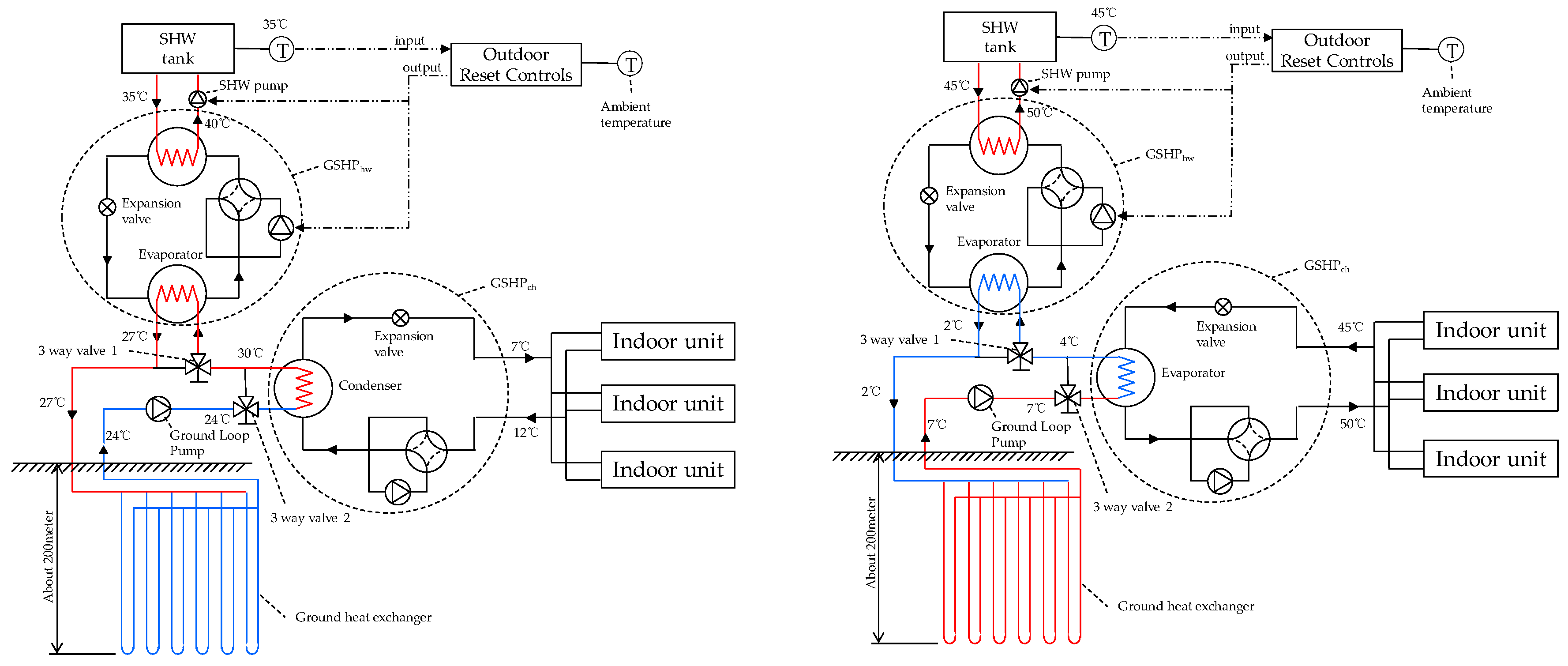
hw.As depicted in
Figure 1, during heating, the groundwater enters the evaporator of the GSHP
ch at a design inlet temperature of 7 °C and leaves the evaporator at 4 °C. The water then passes through three-way valve 2 (full valve opening), enters the evaporator of the GSHP
hw, leaves the evaporator at a design outlet temperature of 2 °C, and eventually returns to the ground heat exchanger. To prevent supercooling when the water passes through two evaporators, domestic guidelines [
20] recommend the addition of 13%–20% antifreeze (ethyl alcohol) to the ground loop water, while maintaining an LWT of 4 ± 4 °C.
When the GSHPch is used for cooling, water at a design temperature of approximately 24 °C from the ground heat exchanger enters the condenser of the GSHPch. The water is then heated by the refrigerant in the condenser and is discharged at approximately 30 °C. The water then passes through three-way valve 1 (fully closed), flows into the evaporator of the GSHPhw, and then transfers the heat to the refrigerant of the evaporator. Finally, the water is discharged at a design temperature of 27 °C and returns to the ground heat exchanger.
Another advantage of sharing a ground loop is that only a single circulation pump is required, whereas at least two pumps are necessary for individual loops. Hence, the overall pumping power can be reduced while increasing the system’s COP.
4.2. Outdoor Reset Controls and Sequential Operation
Although it was verified that the larger heat exchanger capacity of the shared ground loop raises the EWT of the GSHPch (compared to the separated ground loops), if both heat pumps continue to operate concurrently during the heating season, then the EWT of the GSHPch will eventually decrease rapidly. However, because SHW can be stored in the tank before heating begins, the GSHPhw operates while the GSHPch is in stand-by mode. The SHW tank can then be heated intermittently when the hot water temperature drops below a certain threshold. This means that the sequential operation of heat pumps could enhance the long-term thermal resiliency of the ground heat exchanger and increase the energy savings.
Based on Korean Agency for Technology and Standards (KATS)’s guide for the outdoor reset control of DHW temperature, Equation (1) is devised:
where T
DHW is the DHW supply temperature, and T
amb is the ambient temperature.
A typical GSHP
hw provides hot water at a temperature of around 45 °C year-round regardless of regional conditions [
21], while an OARC reduces this temperature to as low as 35 to 40 °C except during severe cold spells when the annual daily mean temperature is below 8 °C.
This study modifies Equation (1) slightly to improve controllability, with the OARC monitoring the outdoor temperature in real-time and adjusting the SHW in a stepwise manner, as shown in
Figure 2. When the temperature of the hot water tank reaches the set-point temperature (positive hysteresis), the GSHP
hw and service hot water pump turn off; they turn on again if the tank water temperature drops below the set-point temperature (negative hysteresis). In the present study, the temperature ranges were determined by the research team based on their knowledge of the municipal climate.
Figure 3 compares the average monthly SHW supply temperature for the stepwise OARC (
Figure 2) and for Equation (1). No noticeable difference was observed between the two reset controls.
In terms of controllability, the service manager of the test hotel manually determines the set-point temperature for the hot water (as in most domestic hotels), thus automatic changes in this set-point temperature according to the real-time OAT does not appear feasible. As an alternative, the service manager or a prescheduler can decide the SHW set-point temperature for the day based on the OAT forecast as long as no drastic variation in the OAT is observed.
5. Simulation Analysis
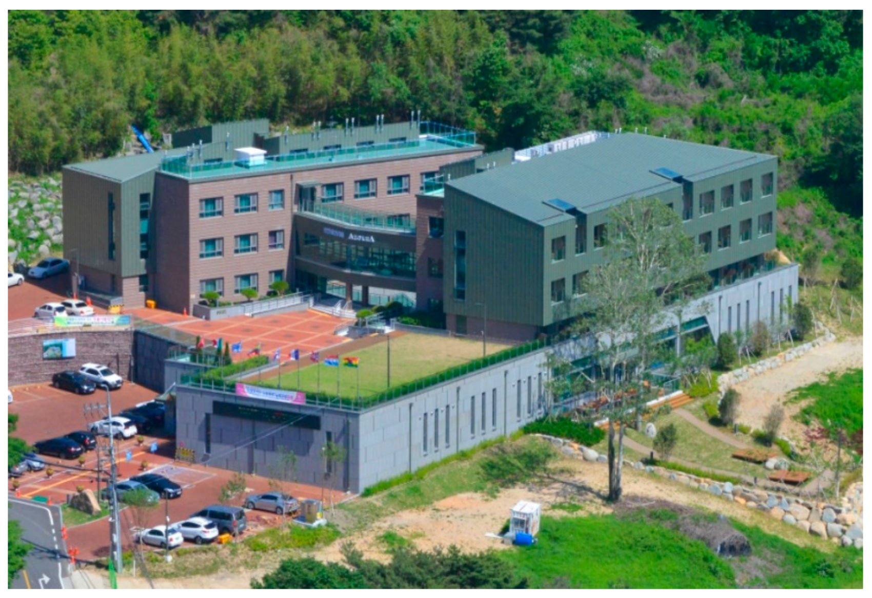
The integrated geothermal system was installed in a hotel in Daegu, South Korea (
Figure 4). Because the test hotel was open for business, the use of an OARC to reduce energy costs could not be verified using field testing; thus, simulation-based M&V was employed. A simulation model was constructed and its properties were calibrated by comparing measured operational data with the simulation results. The OARC of the hot water supply and operation sequence of GSHPs were then loaded on top of the base model. The annual energy savings were estimated and compared with other conventional system configurations and legacy operations. It should be noted that the data collection, construction of the base mode, and subsequent M and V analysis were conducted and reported in a previous study [
3]. However, they are summarized here to aid in the understanding of the present study.
5.1. Test Site and System Description
The test hotel has three stories and two underground floors, providing a total floor area of around 6100 m
2. The integrated geothermal system provides SHW and air conditioning for public areas (2500 m
2), including the lobby, hallways, kitchens, restaurants, fitness shower rooms, and conference halls. Three GSHP
ch and one GSHP
hw were installed in the integrated geothermal system and they share a ground loop. One single GLP circulates the water through all the four heat pumps. The specifications of the system components are presented in
Table 1.
More than 60 indoor units are linked to the GSHP
chs via a refrigerant loop. Because serviced spaces have diverse and variable heating and cooling demands, the direct digital control (DDC) system shown in
Figure 5 provides both sequential and capacity control of the three air conditioning heat pumps (GSHP
ch-1, GSHP
ch-2, and GSHP
ch-3), by summing the heating and cooling demand every hour in real-time and then assigning balanced loads to the heat pumps on duty. Air conditioning is provided from 14:00 to 23:00, following the hotel’s business policies.
The service hot water generated by the GSHP
hw is stored in a 200 L tank and used to meet hot water demand at the set temperature. Because this SHW demand fluctuates depending on the number of guests, the water level and temperature of the hot water tank are kept constant. The GSHP
hw operates intermittently after the baseline volume is met every day. An independent DDC system is attached to the GSHP
hw and hot water tank (
Figure 5), allowing the temperature of the hot water used to meet demand to be prescheduled or overridden by the service manager.
5.2. TRNSYS Model Construction
The base simulation model was developed using TRNSYS with collected data. Weather observations for 2017 taken from the weather station closest to the test building were employed to simulate weather data. The physical envelope properties, such as window–wall ratio, U-value, solar heat gain coefficient (SHGC), and reflectivity, were set according to the building design specifications. The air conditioned and non-air-conditioned spaces were separated and the air conditioned spaces grouped into the same heating, ventilation, and air conditioning (HVAC) zone. For the non-air-conditioned area, the rooms were separated and their construction clearly designated to model the heat capacity of the structure so that it followed the actual behavior as closely as possible. While indoor units were served by the GSHPs, other air conditioned spaces served by other systems were assumed set with an indoor temperature of 20 °C and a humidity of 50%. The ventilation rate was set to an air change per hour of around 1.0. Internal and external loads (e.g., occupants, equipment, lighting, external infiltration, outdoor air intake) were specified according to the building and system design document. Further modeling details can be found in [
3].
On this base model of the test hotel, four configurations of geothermal system were constructed and compared: (a) conventional GSHPs with their own ground loop, (b) integrated GSHPs in a shared ground loop (i.e., an integrated geothermal system), (c) an integrated geothermal system with OARC for SHW in which both heat pumps operate concurrently, and (d) an integrated geothermal system with the OARC for SHW in which the GSHPhw operates earlier than the GSHPch during the heating season.
The specifications and capacity of the GSHPs and the hot water tank were the same for the four configurations. However, as listed in
Table 2, the number of the boreholes and the corresponding GLP capacity were adjusted for each system, while the total capacity was kept constant. Except for the set-point temperature for the hot water and the heat pump operation sequencing, the same controls, including the air conditioning set-points and on/off conditions, were used for each configuration.
When the OARC for SHW was employed in the integrated geothermal system, the GSHPch and GSHPhw operate concurrently during the cooling season, with the GSHPhw operating from 14:00 to 16:00 and the GSHPch operating from 14:00 to 23:00. During the heating season, however, either the GSHPhw operated earlier (08:00 to 11:30) or the GSHPhw operated concurrently with the GSHPch (14:00 to 17:30).
5.3. Data Collection and Model Calibration
TRNSYS base models for the four system configurations were constructed as described in
Section 5.1. Because the integrated geothermal system was already installed in the test hotel, observed data were used to calibrate the models. The inlet and outlet water flow rates, temperature, and power consumption of the heat and groundwater pumps were collected every minute for various air conditioning and hot water supply scenarios. Observational data were collected for two weeks of changing seasons starting on 20 October 2017. The COPs of the GSHP
ch and GSHP
hw were calculated for each scenario by adjusting the three-way valve shown in
Figure 5 in two ways: (i) conventional operation, in which the GSHP
ch and GSHP
hw, have their own ground loop and operate individually for air conditioning and SHW supply, respectively, and (ii) concurrent operation, in which both the GSHP
ch and GSHP
hw share a ground loop and operate concurrently in both summer and winter. Note that conventional individual heat pumps operate with the GSHP
ch and GSHP
hw taking turns, and only the number of ground heat exchangers that correspond to the capacity of the running heat pumps are activated (by closing the valve for the remaining heat exchangers).
Because the system is employed in a hotel, hot water demand was almost always present, but the cooling and heating demand was not constant because the testing period occurred during the change in seasons. Cooling demand was thus artificially manipulated by heating the indoor air using portable heaters and with partial outdoor air intake, while heating demand was artificially manipulated by cooling the indoor air using portable coolers and humidifiers. To artificially produce constant cooling and heating demand, the portable heaters and coolers were turned on and off repeatedly, but it was difficult to maintain a consistent indoor air temperature at around 20 °C for a sufficient period of time. Hence, the inlet and outlet water flow rates, temperature, and power consumption were measured when the inlet and outlet temperatures of the GSHPs were maintained at a relatively steady state after operating the GSHP
ch and GSHP
hw continuously for one to two hours. In addition, the thermal conduction of the ground heat exchanger was calculated to be about 2.05 W/m·K [
3].
All simulations were performed around a month in advance before the measurements began to determine that the ground thermal environment and heat balance were as close to the actual state as possible. The observational and simulation results for conventional individual operation and concurrent operation were compared, and the base model was calibrated by modifying the base model properties to produce a normalized mean bias error (NMBE) within ±10% and a coefficient of variation for the root mean square error (CV–RMSE) within ±30% [
22,
23,
24]. During the calibration process, all TRNSYS variables were set to fall within the error range of the actual values to the greatest extent possible. Thus, great efforts were made to maintain consistency for the inductive analysis of the test scenarios. However, the calibration process involves significant trial and error because of fluctuations and noise in the observational data. Accordingly, calibration was conducted by focusing on modification and adjustment to identify a reasonable point at which the deviation for all of the variables was as uniform as possible.
Because the EWT, LWT, and COP are key parameters for judging ground source heat pump performance, the NMBE and CV–RMSE for these parameters for the GSHP
ch and GSHP
hw when comparing the calibrated model with the observed measurements are presented in
Table 3. It should be noted that cooling tests during summer and heating tests during winter would have been the most desirable research design, but the demonstration test was carried out during the fall, which had a smaller load overall. This is why the results tended to exhibit small differences between the inlet and outlet temperatures (i.e., the difference between the EWT and LWT).
6. Comparisons of Seasonal and Annual Electricity Uses
The calibrated base model for the integrated geothermal system was modified according to the OARC for SHW (
Figure 2). In addition, the GSHP
hw was modified to operate either concurrently with or earlier than the GSHP
ch during the heating season.
Table 4 presents ranges of EWTs, LWTs, and entering water flow rates of GSHP
ch and GSHP
hw for cooling and heating seasons. Compared to the conventional system, EWT
ch of the integrated system decreased and its EWT
hw increased in the cooling season because waste heat of GSHP
ch was reused as an evaporation heat source for GSHP
hw (
Figure 6 and
Figure 7). If an OARC for SHW was added to the integrated system, only slight drops of EWT
ch and EWT
hw were observed (
Table 4). In the heating season, both average EWT
ch and average EWT
hw of the integrated system increased because the full flow volume of the shared ground loop was solely consumed by GSHP
ch first, which means the larger evaporation heat source capacity made the EWT
ch drop smaller. When an OARC was applied and heat pump sequential operation was employed to the integrated system, average EWT
ch became even higher, which leads to an average EWT
hw higher as well (
Figure 8 and
Figure 9). It is because two equivalent-sized evaporators worked in sequence instead of concurrent operation, ground temperature drop became smaller.
Figure 10 and
Figure 11 clearly show that the valley bottom of EWT
ch was about 1.5 K higher and the valley bottom of EWT
hw was about 3 K higher when the OARC and the heat pump sequential operation were employed in the integrated system.
Table 5 presents the estimated annual electricity use for the four system configurations. During the cooling season, heat recovery operation by the integrated geothermal system required about 80.9% of the electricity used by the conventional system. If the OARC for SHW was incorporated into the model, only about 73.4% of the electricity used by the conventional system was consumed. During the heating season, the integrated geothermal system required about 90.4% of the electricity used by the conventional system. If the OARC for SHW was employed and the GSHP
hw operated earlier than the GSHP
ch (i.e., when the GSHP
ch is idle), then only 85.7% and 74.6% of the conventional electricity levels were used, respectively.
When the heating season was analyzed in more detail, it was found that, when both heat pumps shared a ground loop and operated concurrently, electricity savings of only about 10% were achieved compared to the conventional system. These savings were attributed to the lower ground loop pumping energy required. When the OARC was introduced, around 85.7% of the electricity expended by the conventional system was required due to the drop in the hot water supply temperature. However, if the GSHPhw operated earlier when the GSHPch was on stand-by, the electricity use for heating and SHW dropped to about 75.7% and 63.8% of the conventional system, respectively, although pumping electricity returned to 100%. Because each heat pump individually takes advantage of the larger heat capacity of the full ground heat exchanger, the EWTs for both heat pumps eventually increased (compared to other configurations), leading to a reduce in their compression ratio and a subsequent increase in the COP.
During the cooling season, when the integrated geothermal system is in waste heat recovery mode, the electricity use for hot water was reduced to about 85.9% of that for the conventional system because the condensation heat discharged from the GSHPch was used as an evaporation heat source by the GSHPhw, thus increasing the EWThw. When the OARC was incorporated, electricity use decreased to about 54.4% of that of the conventional system as a result of the higher supply water temperature.
7. Economic Analysis
7.1. Initial Cost Breakdowns
It was estimated that, if the initial cost of the integrated geothermal system was installed in the test hotel, it would cost around 310 million South Korean won (KRW) (
Table 6), including 120 million for boring (24 boreholes), 60 million for the purchase and construction of the heat pump outdoor and indoor units, 40 million for the construction of the groundwater pipes and hydraulic system, 12 million for the purchase and construction of single GLP, 18 million for the valves and pumps, and 60 million for electric wiring and automatic controls.
If the conventional geothermal system was installed, it would cost around 300 million KRW (
Table 6). The additional ground loop pump would cost 3 million, but the valves and DDC would become simpler, leading to a savings of 3 million. In addition, the construction complexity of the hydraulic pipes would be lower, thus resulting in savings of 10 million.
It is important to note that OARC or sequential heat pump operation can be introduced at no initial cost.
Compared to two GSHPs sharing a ground loop, the total length of the ground heat exchangers for two separate GSHPs with its own ground loop should be longer. Therefore, the number of boreholes required by the integrated geothermal system may be lower than 24 boreholes, which is optimal for the conventional system. However, this study assumed that the number of boreholes was constant in order to closely examine the extent to which the annual energy cost savings affect the overall economic viability of the integrated geothermal system.
7.2. Annual Electricity Cost Estimation
As presented in
Table 6, the annual electrical costs for the four system configurations were calculated using domestic electricity rates and the annual electricity use as determined by the simulations. Here, an average electricity rate (consisting of 50% of the middle demand window and 50% of the maximum demand window) of 150 KRW per kWh was employed, based on general use as defined by the Korean Electric Power Corporation:
Compared to the conventional system, around 4.9 million KRW in annual electricity costs was saved by using the integrated system;
If an OARC was added to the integrated system and sequential GSHPhw operation employed, about 9.6 million KRW in annual electricity costs could be saved.
7.3. Net Present Value Analysis
The net present value (NPV) for each year was calculated according to Equation (2), assuming that the electricity costs saved each year would remain steady over a 20-year period (which is based on the expected lifetime of a geothermal heat pump). A discount rate of 4% was set [
25]. Because performance degradation due to aging is generally considered in the economic feasibility analysis of GSHPs in the NPV analysis, the underperformance of the GSHPs due to aging was set at 1.5%, including annual maintenance costs [
21]. For example, if the energy savings were calculated to be 100 in the first year after installation, then the savings decrease to 98.5 in the second year due to performance degradation of the GSHPs:
where
Ci denotes the net annual electricity cost savings with the 1.5% aging underperformance for period
i,
r represents the discount rate (4%),
N denotes the number of years, and
I0 is the initial cost difference (for period 0).
Table 7 presents the cumulative annual electricity savings after 1, 2, and 3 years, and the NPV in consideration of aging underperformance and the discount rate. The cumulative annual electricity cost savings for the integrated geothermal system surpassed the initial investment cost difference
I0 after 3 years, while the integrated system with the OARC did so only after 1 year. When sequential heat pump operation was also applied, the break-even point was even earlier than 1 year.
If the integrated geothermal system was installed instead of the conventional geothermal system, and operated for 20 years, electricity cost savings of about 49 million KRW could be achieved assuming today’s present value, after subtracting the initial investment cost difference. When OARC and sequential operation were included, this increased to about 75 million and 106 million KRW, respectively.
8. Discussion
Our previous study [
3] reported that integrated GSHPs on a shared ground loop produced electricity savings of about 10% during the winter season when compared to a conventional configuration. However, the investor wanted to seek additional operation cost savings at no added expense, if possible. This study, therefore, explored control strategies to further increase the energy savings. It was found that the economic feasibility of the system could be significantly improved if an OARC for SHW and sequential operation of GSHPs were incorporated into the integrated geothermal system.
The following findings and implications from this study are of particular importance.
In Korea, because cooling loads are typically larger than heating loads by about 30% to 40% for most buildings, most GSHPs are sized to serve the cooling load [
26]. Hence, the number of boreholes as determined by the cooling load would larger than that determined by the heating load. The proposed integrated geothermal heat pump system has a potential to reduce the number of boreholes required because the GSHP
hw uses the condensation heat from the GSHP
ch, thus reducing the total length of the ground heat exchanger.
However, this study assumed the same number of active boreholes both for the conventional and integrated systems because installing several boreholes to experiment with the conventional geothermal system was not physically feasible.
If the construction cost for a smaller number of boreholes and an equivalent real estate capital cost of the integrated system were accounted for, the economic advantages of the proposed integrated system would increase further. For instance, removing two boreholes would save about 10 million KRW of the initial cost. If the test site were located in the heart of Seoul, however, the initial cost reduction by smaller occupied area due to removing two boreholes could be more than 100 million KRW. However, because boreholes were installed in the parking lot of the test hotel, which still has more open-air areas, accounting for the area occupied by ground heat exchangers would have little impact on the cost increase or decrease. Therefore, the economic analysis in this study was mainly driven by annual electricity savings rather than initial investment costs.
When the GSHPhw operated earlier than the GSHPch during the winter season, the electricity use for both heating and hot water was lower than that for the concurrent operation of both heat pumps. This is because each GSHP exclusively uses the shared ground heat exchanger as an evaporation heat source. However, the longer pump running hours led to greater electricity use. Although sequential operation turned out to be more efficient in this study, this could differ according to the complex thermodynamics of individual system set-ups, depending on the pump size, the length of the ground heat exchanger, the fluid/refrigerant type, the local climate, the annual ground temperature profile, and the favored heating and hot water set-points. Thus, the decision to implement sequential operation should be based on investigative simulations.
In the previous study, it was observed that an increase in the EWThw led to an increase in the LWThw, particularly during the cooling season, which caused the load control of the compressor and the expansion valve of the GSHPhw to become unstable under part-load conditions, while also causing the fluid flow rate to fluctuate irregularly. When an OARC is employed in summer, the lower set-point temperature for the hot water (i.e., by lowering the condensation temperature) would accelerate this issue. This study attempted to resolve this by increasing the supply water flow rate of GSHPhw, thus increasing the hot water demand and shifting GSHPhw closer at a full-load operation condition. Unfortunately, this could not be verified in the simulations. Thus, a sufficiently long observation is necessary to determine whether the increased water flow rate is able to resolve load-control issues under part-load conditions.
Because OARC is preferred to district heating, which is a common residential plant system employed in Korea, a hot water temperature of 35 °C during summer is not unusual for guests. However, hotter water is often requested by some guests. As such, it may be necessary to raise the supply temperature of hot water to 40 °C in summer.
9. Conclusions
In the previous study, an integrated geothermal system in which the waste heat flowing into the ground was recovered by sharing a ground loop was developed. In addition to its lower electricity consumption compared to the conventional combination of air conditioning and SHW heat pumps, in which cooling, heating, and hot water are supplied separately on separate ground loops, and the developed system increases the hot water supply flow when the heating demand decreases. In other words, the developed system can supply more hot water or hotter water without placing an extra load on the system. However, due to practical concerns that the energy savings may be somewhat low during the winter season for the proposed system, ECMs that could improve its economic feasibility by minimizing lifetime energy costs without increasing the initial investment cost were sought. As a result, the OARC for SHW and the sequential operation of the ground source heat pumps were investigated in terms of their electricity savings and economic feasibility. The key findings follow.
- (1)
Reductions of around 27% and 15% in electricity use during the cooling and heating seasons, respectively, could be achieved compared to a conventional geothermal system if OARC for SHW was applied to the proposed system. If the heat pump operational sequence was optimized, electricity savings of around 25% during the heating season were expected. In conclusion, the proposed integrated geothermal system can achieve annual electricity savings of 25% compared to the conventional combination of air conditioning and hot water heat pumps.
- (2)
Around 4.9 million KRW a year in electricity costs can be saved using the integrated geothermal system, compared to the conventional system. If OARC and sequential heat pump operation are also applied, up to 9.6 million KRW a year can be saved in electricity, corresponding to about 3% of the initial installation cost.
- (3)
The NPV was calculated by setting a discount rate of 4% and an aging performance degradation rate of 1.5% (including annual maintenance costs) and by assuming that the lifetime of a geothermal heat pump is 20 years. The cumulative electricity savings became higher than the initial investment cost difference after three years of operation. However, the break-even point became earlier than one year if OARC and sequential heat pump operation were employed in the integrated geothermal system.
- (4)
If the integrated geothermal system was installed and OARC and sequential heat pump operation employed for 20 years, electricity savings of about 106 million KRW were possible compared to the conventional system, excluding the initial investment cost difference.
The space heating demands of newly built residential facilities are expected to gradually decrease in the future because the regulations for envelope insulation and the infiltration rate have been strengthened for new buildings, while hot water supply demands are gradually increasing. The integrated geothermal system, therefore, is expected to supply more SHW (as compensation for low space heating demand) without increasing the energy use of the entire system. Thus, its economic feasibility is likely to be higher for new residential buildings.


