Article

Evaporative Cooling Options for Building Air-Conditioning: A Comprehensive Study for Climatic Conditions of Multan (Pakistan)

1
Department of Agricultural Engineering, Bahauddin Zakariya University, Multan 60800, Pakistan
2
Department of Mechanical Engineering, Bahauddin Zakariya University, Multan 60800, Pakistan
*
Author to whom correspondence should be addressed.
Energies 2020, 13(12), 3061; https://doi.org/10.3390/en13123061
Submission received: 18 May 2020 / Revised: 7 June 2020 / Accepted: 8 June 2020 / Published: 12 June 2020
(This article belongs to the Section G: Energy and Buildings)

Abstract

:
This study provides comprehensive details of evaporative cooling options for building air-conditioning (AC) in Multan (Pakistan). Standalone evaporative cooling and standalone vapor compression AC (VCAC) systems are commonly used in Pakistan. Therefore, seven AC system configurations comprising of direct evaporative cooling (DEC), indirect evaporative cooling (IEC), VCAC, and their possible combinations, are explored for the climatic conditions of Multan. The study aims to explore the optimum AC system configuration for the building AC from the viewpoints of cooling capacity, system performance, energy consumption, and CO2 emissions. A simulation model was designed in DesignBuilder and simulated using EnergyPlus in order to optimize the applicability of the proposed systems. The standalone VCAC and hybrid IEC-VCAC & IEC-DEC-VCAC system configurations could achieve the desired human thermal comfort. The standalone DEC resulted in a maximum COP of 4.5, whereas, it was 2.1 in case of the hybrid IEC-DEC-VCAC system. The hybrid IEC-DEC-VCAC system achieved maximum temperature gradient (21 °C) and relatively less CO2 emissions as compared to standalone VCAC. In addition, it provided maximum cooling capacity (184 kW for work input of 100 kW), which is 85% higher than the standalone DEC system. Furthermore, it achieved neutral to slightly cool human thermal comfort i.e., 0 to −1 predicted mean vote and 30% of predicted percentage dissatisfied. Thus, the study concludes the hybrid IEC-DEC-VCAC as an optimum configuration for building AC in Multan.

Graphical Abstract

1. Introduction

Air-conditioning (AC) loads of buildings are increasing rapidly due to the increase in population, urbanization, and standards of living [1]. Although, many environment friendly AC systems are used nowadays that are free from HCFC/HFC refrigerants. However, there are many environmentally harmful systems that are still under practice to control/regulate temperature and humidity. Thus, increasing AC use is somehow responsible for global warming and CO2 emissions around the globe [2]. Alternatively, heat-driven adsorption/ absorption-based environment friendly AC systems are also in practical use [3,4]. In 2017, worldwide global electricity consumption in the residential sector was around 496,583 and 398,729 ktoe in commercial and public sector buildings, respectively [5]. Heating, ventilation and air-conditioning (HVAC) of buildings consume a huge amount of total building electricity, which is also responsible for the increase in CO2 emissions [6,7]. Therefore, environment friendly HVAC systems are principally needed worldwide. Evaporative cooling systems could provide low-cost and environment friendly alternative options for building AC load management. In some studies, the evaporative cooling systems are coupled with a conventional vapor compression air-conditioning (VCAC) system to achieve the desired levels of AC [8,9,10,11,12].
Evaporative cooling is a renowned and vintage cooling concept by which cooling is produced due to water-vapor evaporation into the process air. These systems are usually classified as direct (DEC), indirect (IEC), Maisotsenko-cycle i.e., M-cycle (MEC) evaporative cooling systems [2]. Standalone evaporative cooling systems usually achieve smaller temperature flux followed by lower cooling capacity as compared to VCAC systems, therefore, hybrid systems have also been explored in the literature [9]. In addition, several experimental and theoretical researches have been conducted for standalone and multistage evaporative cooling systems to achieve the required conditions of temperature and humidity. These include (but not limited to) IEC-DEC [13,14,15], DEC-IEC [16], VCAC-IEC [17], IEC-VCAC [18,19], DEC-VCAC [20,21,22], and IEC-DEC-VCAC [23].
A combined parallel-regenerative cooler was comparatively studied along with bi-stage counter flow and parallel flow indirect evaporative coolers [24]. Wet-bulb effectiveness (WBE) of the parallel-regenerative cooler was highest (i.e., 1.31) among the other configurations. An IEC system was coupled with VCAC, which drops 75% cooling load [25]. According to an experimental investigation [26], WBE of 1.11 is achieved in case of IEC-DEC system. In addition, power consumption dropped up to 60% when compared to VCAC system [26]. A numerical study for Mediterranean region employed a passive DEC system for the AC load management of an office buildings. The DEC resulted in being an effective cooling system in Eastern Mediterranean and southern Spain [27]. A spatiotemporal analysis of cooling potential of evaporative coolers and direct ventilation cooling techniques was performed in Iberia. Cooling thermal load savings in direct ventilation and evaporative cooling were 27% and 40%, respectively [28]. Lost heat in exhaust air was recovered by utilizing an evaporative cooling system in ventilation. Temperature gradients of 2.2 °C and 7.5 °C were observed at outside air temperatures of 24.4 °C and 35.7 °C, respectively. It shows that evaporative cooling efficiency is dependent on ambient air temperature [29]. Downdraught evaporative cooling was applied to official and public buildings. Dry bulb (DBT) minus wet-bulb (WBT) temperature index (DBT-WBT) was estimated for United States of America [30], which also justifies the dependence of the ambient air temperature.
Nowadays, many heat-driven AC systems such as adsorption/absorption systems are used which not only use environment friendly refrigerants but also use renewable energy sources. Therefore, these systems can also help to provide an alternative environment friendly AC system. Consequently, integration of desiccant units into evaporative coolers has been extensively studied in the literature to provide a sustainable solution [31,32,33]. Cooling capacity of a liquid desiccant system was enhanced by 41% when coupled with a dew-point IEC system [34]. Another evaporative cooling-assisted liquid desiccant system resulted in 12% lesser primary energy consumption for building cooling as compared to VCAC [35]. In addition, an evaporative cooling-based liquid desiccant system was experimentally investigated. A temperature gradient of 5.5 °C was found in the supply air [36]. Human thermal comfort for buildings was evaluated using evaporative cooling-based liquid desiccant AC system [37]. Predicted mean vote (PMV) method was used to determine the overall thermal comfort using TRNSYS simulation. The PMV was within the acceptable range of Standard 55 provided by American Society of Heating, Refrigerating and Air-Conditioning Engineers (ASHRAE). Similarly, solid desiccant system assisted by dewpoint evaporative cooler resulted in a 65% more efficient system than standalone desiccant AC (DAC) system [38]. Apart from building AC, the desiccant [39,40] and evaporative cooling systems have been investigated for various applications including agricultural product storage [41], greenhouse air-conditioning, and livestock air-conditioning etc. [41,42,43,44,45,46].
According to the above discussion, a thumb rule for evaporative cooling dictates “The hotter, the better”. Thereby, locally developed low-cost evaporative coolers are extensively used in Pakistan due to its typical summer conditions [47,48]. The Köppen–Geiger climate classification map for Pakistan is provided in Figure 1, which highlights considerable variation of climatic conditions across the country. Buildings in Pakistan are generally built with brick wall with low to moderate insulation without any AC load calculation. The VCAC systems are usually preferred in commercial buildings, however, it is not financially feasible at least for low-income residents [21,49]. Therefore, multistage and/or hybrid types of evaporative coolers could be an eye-catching solution for providing desired conditions throughout year. Consequently, seven kinds of evaporative cooling configurations (DEC, IEC, VCAC, IEC-DEC, DEC-VCAC, IEC-VCAC, and IEC-DEC-VCAC) are explored in this study for climatic conditions of Multan (Pakistan). The effectiveness of evaporative cooling systems is determined from the lab-scale experimental apparatus, which are used as design values for DesignBuilder simulation. Building AC load of Agricultural Engineering Department of Bahauddin Zakariya University and associated human thermal comfort were estimated in EnergyPlus. Cooling capacity, coefficient of performance (COP) and reduction in CO2 emissions by the systems were investigated and compared accordingly.

2. Proposed Evaporative Cooling Systems’ Configuration

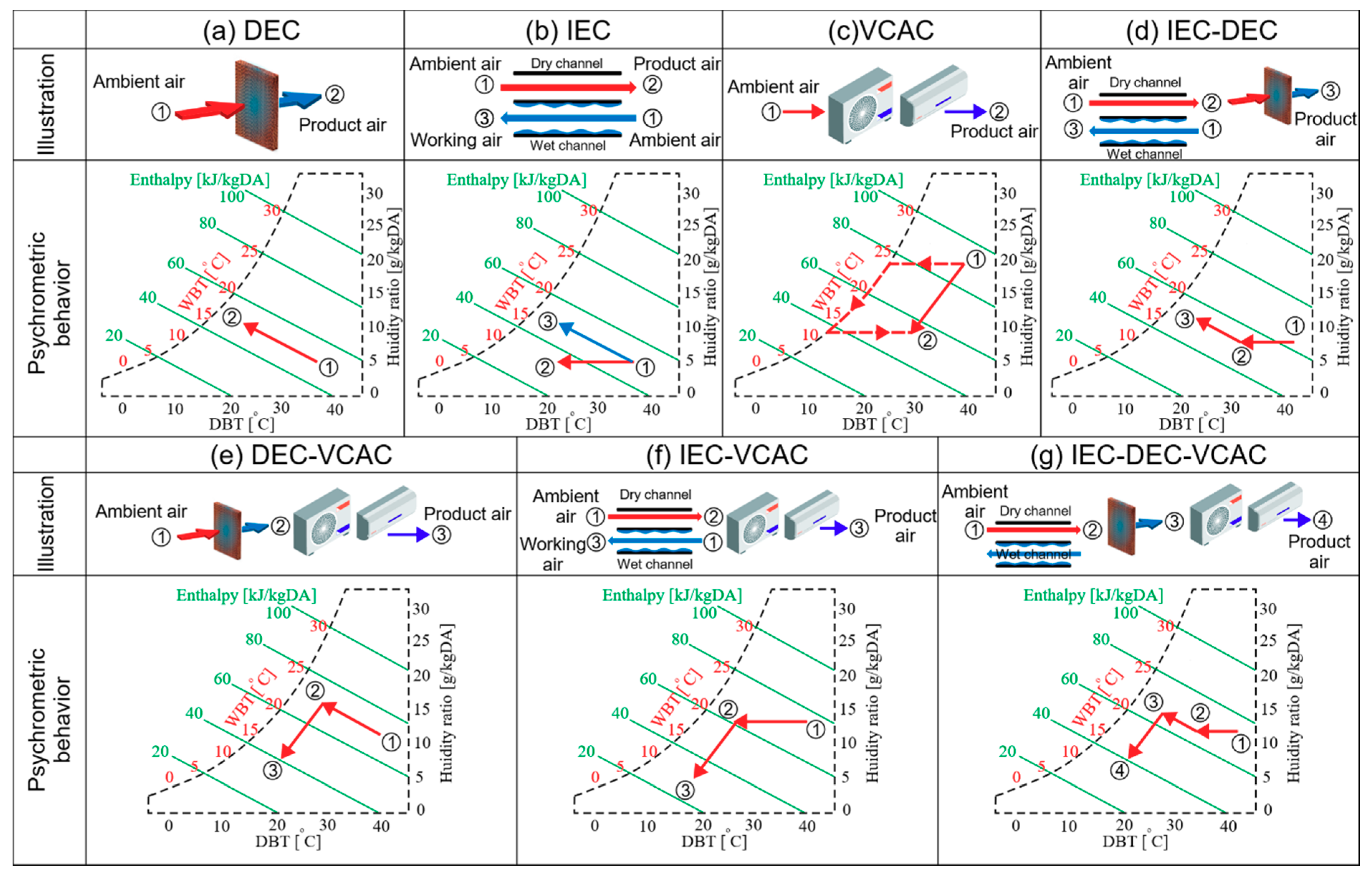
As the study area lies in a warm desert (hot and dry) climate (BWh) class of Köppen climate classification system [47], therefore, the EC systems are usually operated in the region except for monsoon (rainy) season. However, the potentials of multistage EC and hybrid systems are not explored as far as the local market of Pakistan is concerned. Therefore, this study investigates seven combinations of EC and VCAC systems, which are named as: (a) DEC, (b) IEC, (c) VCAC, (d) IEC-DEC, (e) DEC-VCAC, (f) IEC-VCAC, and (g) IEC-DEC-VCAC. Schematic illustrations and the corresponding psychrometric behavior are provided in Figure 2a–g, respectively. The key information for each proposed system is provided as follows:
  • DEC system (Figure 2a): It cools process air isenthalpically (process 1–2). The DEC system can cool the process air up to wet-bulb temperature of the ambient air.
  • IEC system (Figure 2b): The working air (process 1–3) is cooled isenthalpically like DEC, and the cooling affect is transferred to product air by heat transfer between wet and dry channels. The fact sensibly cools the product air (process 1–2) up to wet-bulb temperature.
  • VCAC system (Figure 2c): It is the conventional compressor-based vapor compression air conditioning unit that cools the process air below the dew point. The required conditions are obtained by mixing/reheating the product air (process 1–2, dotted line).
  • IEC-DEC (Figure 2d): It is a double stage EC unit that cools the air by indirect (process 1–2) followed by direct (process 2–3) EC concepts.
  • DEC-VCAC (Figure 2e): It is a hybrid system composed of DEC (process 1–2) and VCAC (process 2–3) units.
  • IEC-VCAC (Figure 2f): It is a hybrid system composed of IEC (process 1–2) and VCAC (process 2–3) units.
  • IEC-DEC-VCAC (Figure 2g): It is also a hybrid system that is composed of IEC (process 1–2), IEC (process 2–3) and VCAC (process 3–4) units.

3. Materials and Methods

3.1. Building Energy Simulation

3.1.1. Building Layout

The present study focuses on air-conditioning requirements for the building of the Agricultural Engineering Department of Bahauddin Zakariya University, Multan, Pakistan. The primary layout of the building is shown in Figure 3, which occupies a floor of 3251.7 m2 area and volume of 15,669.0 m3. The details of inputs parameters used for simulation are provided in Table 1 and consist of building geometrical information (height, wall/ roof construction material, glazing/window construction material, and overall heat transfer coefficient), thermal gains, energy efficiency setpoints, and zone-wise AC operation schedule.

3.1.2. Energy Simulation

The DesignBuilder [52] coupled with EnergyPlus [53] is extensively considered as effective and authoritative software for building simulation as compared to eQuest, Elements, and Sketchup [19,54,55,56,57,58,59,60,61,62,63,64,65,66,67,68,69,70,71,72,73,74,75,76]. Therefore, preliminary layout, thermal properties, construction materials, overall thermal coefficient, building symmetry, direction, and all other physical properties for the studied building were designed in DesignBuilder and simulated using EnergyPlus. The proposed seven combinations for AC units (Figure 2) were designed in DesignBuilder using HVAC module in generic loop air handling unit (AHU). Hourly weather data of Multan (Pakistan) are used for the simulation, which was obtained from TRNSYS repository, provided by World Meteorological Organization (WMO) [77], cross checked using station weather data from Meteonorm. A complete fresh air circulation in AHU was selected. The modules of Direct Research Special and Indirect Research Special were selected in DesignBuilder for DEC and IEC analyses with design WBE of 0.90 and 0.605, respectively (Table 1). A direct expansion (DX) cooling coil was used in the case of the VCAC system. Thereby, combinations of single stage, multistage, and hybrid AC systems were successively arranged inside the AHU.
The corridors of the studied building are excluded from simulation as they are exposed to atmosphere. The washrooms area is also excluded from simulation as local design. The operation schedule for seven AC system configuration was selected from 8 am to 4 pm, which are typical office hours in the building.

3.2. Energy Estimations

Wet-bulb effectiveness (WBE) can be calculated by the ratio of temperature differences as given by [2]:
ε w b = T O A , D B T T S A , D B T T O A , D B T T O A , W B T
where, εwb is WBE (-) and T is temperature (°C). The subscripts OA and SA represent outside air and supply air, respectively. The subscripts DBT and WBT represent dry bulb and wet-bulb temperatures, respectively. Cooling capacity (Q) was determined using Equation (2) as given by [78]:
Q = m C p ( Δ T )
where, Q denotes the cooling capacity (kW), m denotes air mass flow rate of ~14 kg s−1, Cp represents specific heat capacity of air (1.005 kJ kg−1 K−1), and ∆T is the difference between outside and supply air temperatures (°C). Coefficient of performance (COP) was defined as the ratio of the cooling effect produced to the work input (prime movers, fans), represented by Equation (3):
COP = Q W
Equation (2) was also used for VCAC with an assumption of no latent heat transfer. However, considering latent heat transfer, Equations (4)–(7) can be used as given by [53]:
m = ρ a i r u
Q n e t = m ( h o u t h i n )
Q s e n s i b l e = m ( h o u t h i n ) X m i n
Q l a t e n t = Q n e t Q s e n s i b l e
where, ρair represents density of air (kg m−3), u denotes the user-set volumetric flow of air (m3 s−1), hout is total enthalpy of the air at supply side (J/kg), hin is total enthalpy of the air at inlet side (J/kg), Xmin is minimum of inlet and outlet air humidity ratios (kg/kg), Qnet is the total cooling capacity (W), Qsensible is the total sensible energy transfer (W), and Qlatent is the total latent energy transfer (W).

3.2.1. Cooling Loads

Cooling loads faced by the AC system were classified into transmission, infiltration, internal, and equipment loads. Transmission loads are mainly generated from heat transfer from walls, roof, basement, and windows. Infiltration loads include air change through the opening of doors, clearance beneath the doors, cracks, and crawl spaces. Internal loads include heat generated from the human body, lighting, appliances, and solar heat gain from windows through conduction. Heat generated from the human body depends on the level of activity of the body in terms of metabolic rate. Typically, a seated office worker generates 65 W m−2 [50] heat varied by body surface area as given by Equation (8) [79]:
A r e a h u m a n   b o d y = 0.202 m a s s 0.425 h e i g h t 0.725
Thermal comfort of a human body mainly depends on operative temperature (approximately equal to the average of dry bulb temperature of air and surrounding surfaces’ temperature), relative humidity and velocity of air. As per well-known heat and mass transfer guidelines by Cengal Y. [80], lower and upper acceptable limits of operative temperature for typical Pakistani shalwar-kameez clothing [50,51] are 18 °C and 23 °C (for winter: 1.145 clo) and 21 °C and 25 °C (for summer: 0.775 clo), respectively, at 50% relative humidity and air flow of 0.15 m s−1 [80]. The heat gains through human body (Qhb), exterior surfaces (Qext), sol-air temperature (Ts-a), walls (Qwall), fan motors (Qm), floor (Qsp), windows (Qglazing), air change per hour (ACH), sensible infiltration (Qs,i), and latent infiltration (Ql,i) were calculated by Equations (9)–(18), respectively [80]. For details, please refer to the cited literature [78].
Q h b = ( Q s e n s + Q l a t ) s k i n + ( Q s e n s + Q l a t ) l u n g s
Q e x t = h o A s ( T a T s ) + α s o l a r A s q s o l a r Ε A s φ ( T a 4 T s u r 4 )
T s a = T a + α s o l a r q s o l a r h o Ε φ ( T a 4 T s u r 4 ) h o
Q w a l l = U w a l l A s ( T s a T i n )
Q m = P r L f U f η m
Q s p = U f l o o r P f l o o r ( T i n T o u t )
Q g l a z i n g = Q c + Q e + Q f = U g A g ( T i n T o u t )
A C H = m i n V
Q s , i = ρ a i r C p A C H   V ( T i n T o u t )
Q l , i = ρ a i r h f g A C H   V ( X i n X o u t )
where, Qhb denotes total heat generated from human body (W); Qsens represents sensible heat gain from the skin and lungs; Qlat represents latent heat from the body (sweating, moist breath); ho represents heat transfer coefficient (W m−2 °C); As represents surface area of the wall (m2); Ta stands for ambient air temperature (°C); Ts represents surface temperature (°C); αsolar represents solar absorptivity constant [81]; qsolar represents incident solar radiation (W m−2); E represents surface emissivity [50]; φ represents solar incident angle relative to the latitude; Tsur represents mean temperature of surrounding surfaces (°C); Ts-a denotes sol-air temperature (°C); Uwall represents wall’s overall heat transfer coefficient (W m−1 °C−1); Tin and Tout represent inside and outside air temperatures, respectively; Qm represents heat gain from motor (W); Pr represents power of the motor (W); Lf represents load factor; Uf represents utilization factor and ηm denotes efficiency of the motor; Qsp represents total heat loss from the floor (W); Ufloor represents overall heat transfer coefficient for the floor (W m−1 °C−1); Pfloor represents floor perimeter (m); Qglazing represents total heat transfer through the windows; Qc, Qe, and Qf represent heat transfer through center, edge and frame of the windows, respectively; Ug represents overall heat transfer coefficient of the window; Ag denotes surface area of the window; ACH represents air change/hour; min represents air infiltration inflow rate (m3 h−1); V represents building volume (m3); Qs,i and Ql,i represent sensible and latent heat transfer due to infiltration, respectively; hfg represents latent heat of evaporation (kJ kg−1); and Xin & Xout represent inside and outside air humidity ratios (g/g), respectively.

3.2.2. Thermal Comfort Indices

Thermal comfort can be quantified using predicted mean vote (PMV) and predicted percentage of dissatisfaction (PPD) as per Fanger’s model and ISO standard 7730 [82]. Thermal comfort is a structure of various factors including temperature, relative humidity, velocity of air, rate of human body metabolism (directly linked to performance activity), and clothing insulation. It is important to note that PMV is only an average of thermal comfort sensation for a group of persons, so, individual thermal comfort sensation can vary from this average value. To counter this effect, PPD (as a function of ±2 PMV) is introduced. The PMV and PPD was calculated using Equations (19)–(22) [82] and Equation (23) [82]:
P M V = [ 0.303 e ( 0.036 M e t ) + 0.028 ] ( M e t Q w o r k ) 3.05 [ 5.73 0.007 ( M e t Q w o r k ) Ρ a ] 0.42 [ ( M e t Q w o r k ) 58.15 ] 0.0173   M e t ( 5.87 Ρ a ) 0.0014   M e t ( 34 T a i r ) 3.96   e 8   r c b [ ( T c l o t h + 273 ) 4 ( M R T + 273 ) 4 ] r c b   h c o n v ( T c l o t h T a i r )
T c l o t h = 35.7 0.0275 ( M e t Q w o r k ) R c { ( M e t Q w o r k ) 3.05 [ 5.73 0.007 ( M e t Q w o r k ) Ρ a ] 0.42 [ ( M e t Q w o r k ) 58.15 ] 0.0173   M e t ( 5.87 Ρ a ) 0.0014   M e t ( 34 T a i r ) }
h c o n v = { 2.38 ( T c l o t h T a i r ) 0.25 for 2.38   ( T c l o t h T a i r ) 0.25 > 12.1   u a i r 12.1   u a i r for 2.38   ( T c l o t h T a i r ) 0.25 < 12.1   u a i r
r c b = { 1.0 + 0.2   C l o t h i n s u l for C l o t h i n s u l < 0.5   c l o 1.05 + 0.1   C l o t h i n s u l for C l o t h i n s u l > 0.5   c l o
P P D = 100 95   e ( 0.03353 P M V 4 0.2179 P M V 2 )
where, Met represents metabolic rate of the body per unit area (W m−2), Qwork represents heat loss from working human body (W m−2), Pa vapor pressure of ambient air, Tair represents temperature of the conditioned space (°C), rcb represents ratio of clothed to naked body, Tcloth represents temperature of the clothes (°C), MRT represents mean radiant temperature (°C), hconv represents convective heat transfer coefficient of the conditioned space (W m−2 °C−1), Rc represents thermal resistance of clothes (m2 °C W−1), uair represents velocity of air flow (m s−1), and Clothinsul represents insulation of clothes (clo).

4. Results and Discussion

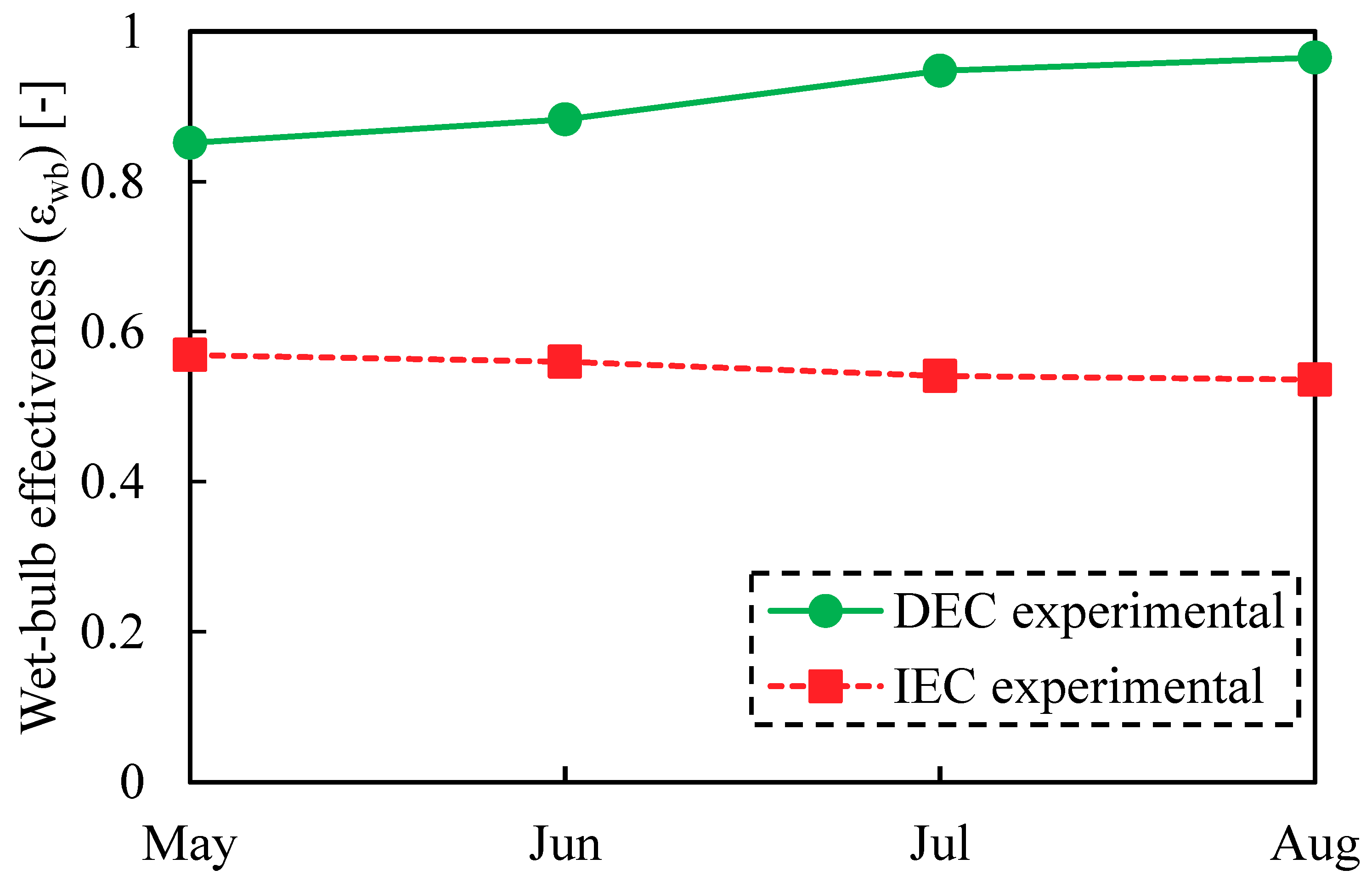
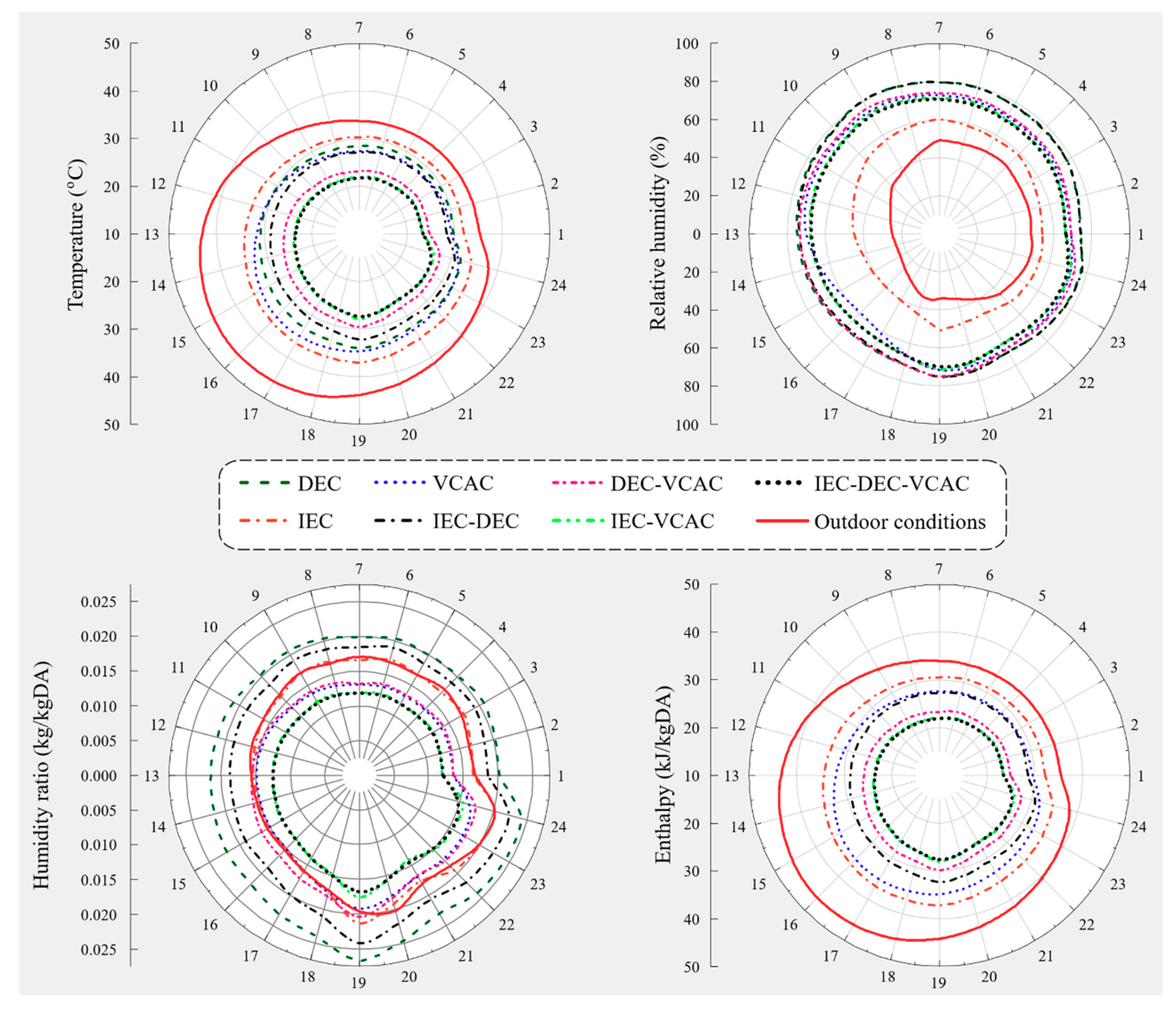
Figure 4 shows the numerical values of WBE achieved by DEC and IEC systems for climatic conditions of Multan (Pakistan) [83]. The effectiveness results presented in Figure 4 cover the typical summer months (i.e., May to August) under Multan conditions. These results are based on the lab-scale DEC/IEC experimental apparatus from the authors’ previous work [83]. The details of experiments are not provided in this study for simplicity and ease of simulation. Consequently, WBE numerical values of 0.90 and 0.605 are used as design values in the simulation models for DEC and IEC systems, respectively (Table 1). Consequently, a simulation model was designed in DesignBuilder and simulated using EnergyPlus to optimize the applicability of the proposed seven systems (Figure 2) for the studied building in Multan (Pakistan). The details of study area, AC load, and simulation are provided in Section 3. Accordingly, the results are presented in Figure 5a–b for a monthly basis, which shows the ambient and product air conditions for all of the seven AC configurations for temperature, relative humidity, humidity ratio, and enthalpy, respectively.
The IEC-DEC-VCAC system provided a temperature gradient of 13 °C (maximum) in May, whereas the IEC system was only able to achieve 4 °C (Figure 5a). It is important to mention that the temperature gradient is defined as the difference between ambient and product air temperatures. The studied hybrid system options (i.e., DEC-VCAC, IEC-VCAC and IEC-DEC-VCAC) performed relatively better as compared to all standalone system options. The standalone VCAC system resulted in a temperature gradient of 7 °C in May, which also produces almost uniform performance irrespective of ambient conditions round the clock throughout the month. Maximum temperature gradient for all configurations was found mostly in May and June months, whereas it was negative in winter months. The DEC system provided a relative humidity difference of 36% (maximum) in May (Figure 5b). The DEC system provided a humidity ratio of 0.000023 kg kg−1 in July (Figure 5c). The DEC system provided the highest enthalpy of 35.13 kJ kg−1 in June (Figure 5d).
In support to the above discussion, an insight of hourly performance variation is presented in Figure 6 for all configurations accordingly. The presented results are depicted for 19 June conditions as a hypothetical representative of a summer day. The findings of these hourly results are not much different, as reported above. Among the studied systems, the IEC-DEC-VCAC system resulted in a maximum temperature gradient i.e., 21 °C (at 3 pm) followed by IEC-VCAC i.e., 20.7 °C (at 3 pm), whereas the IEC system provided the lowest temperature gradient of just 9.8 °C (at 3 pm). From midnight to three past blazing noon, standalone EC systems resulted in a temperature gradient which depended on ambient air. It solidifies the statement that performance of standalone EC systems is dependent on ambient air conditions. In contrast, standalone VCAC and hybrid EC systems were only impacted by varying load. The hybrid EC systems easily meet the required conditions at higher power consumption.
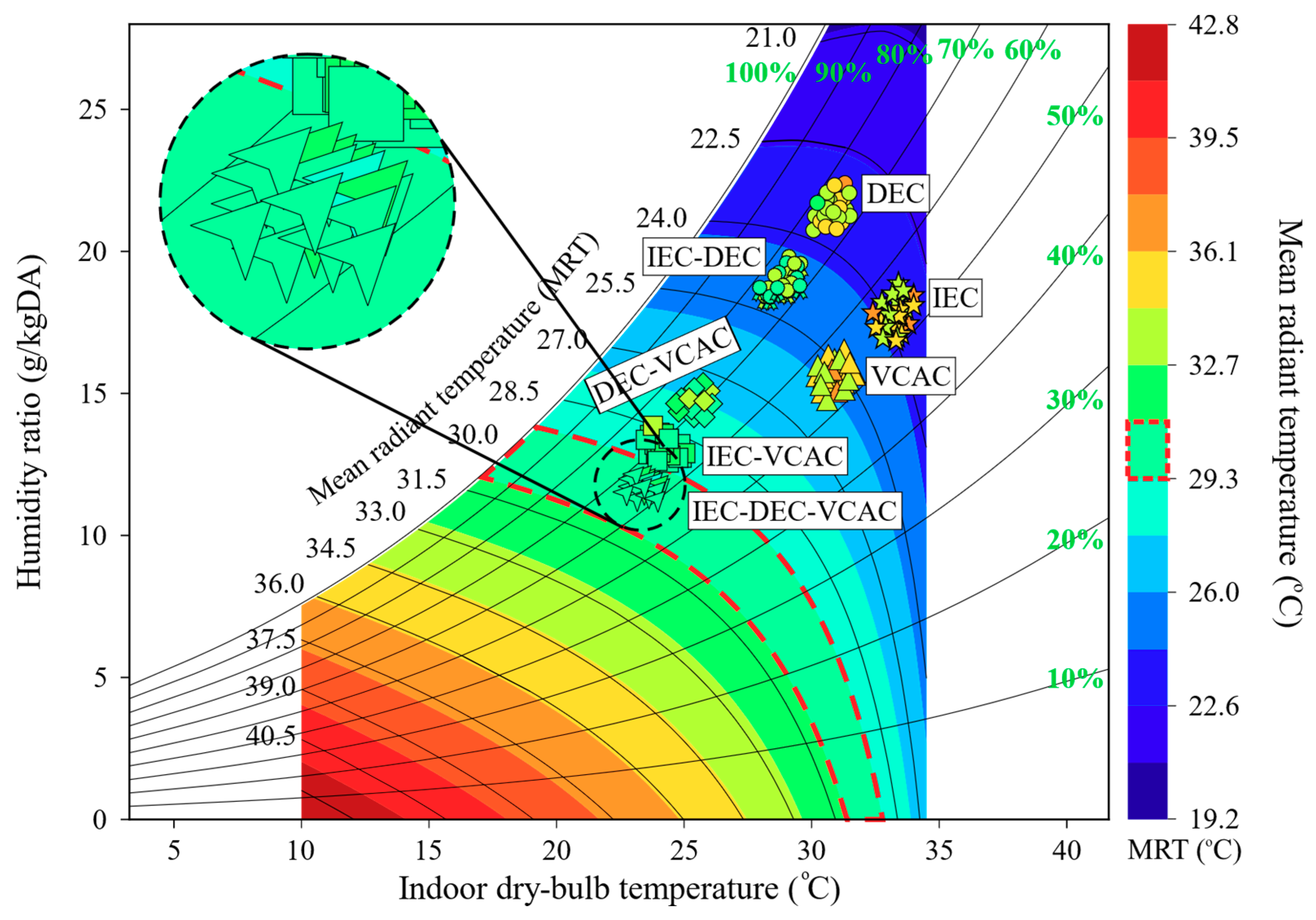
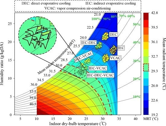
One-day-averaged product air conditions of the seven AC systems are presented in Figure 7. It is worth mentioning that the expanded psychrometric chart with radiation and convection dimensions used in Figure 7 is taken in raw form from a state-of-the-art study authored by Teitelbaum et al. [84]. The IEC-DEC-VCAC resulted in a neutral to slightly cool thermal comfort sensation as per ISO 7730 [82] requirements (with matching mean radiant temperature MRT) for a person doing light office work, whereas the IEC-VCAC system resulted in neutral to slightly warm thermal comfort sensation due to varying MRT. The standalone VCAC resulted in a few shades of discomfort. The DEC showed maximum deviation from its mean radiant temperature.
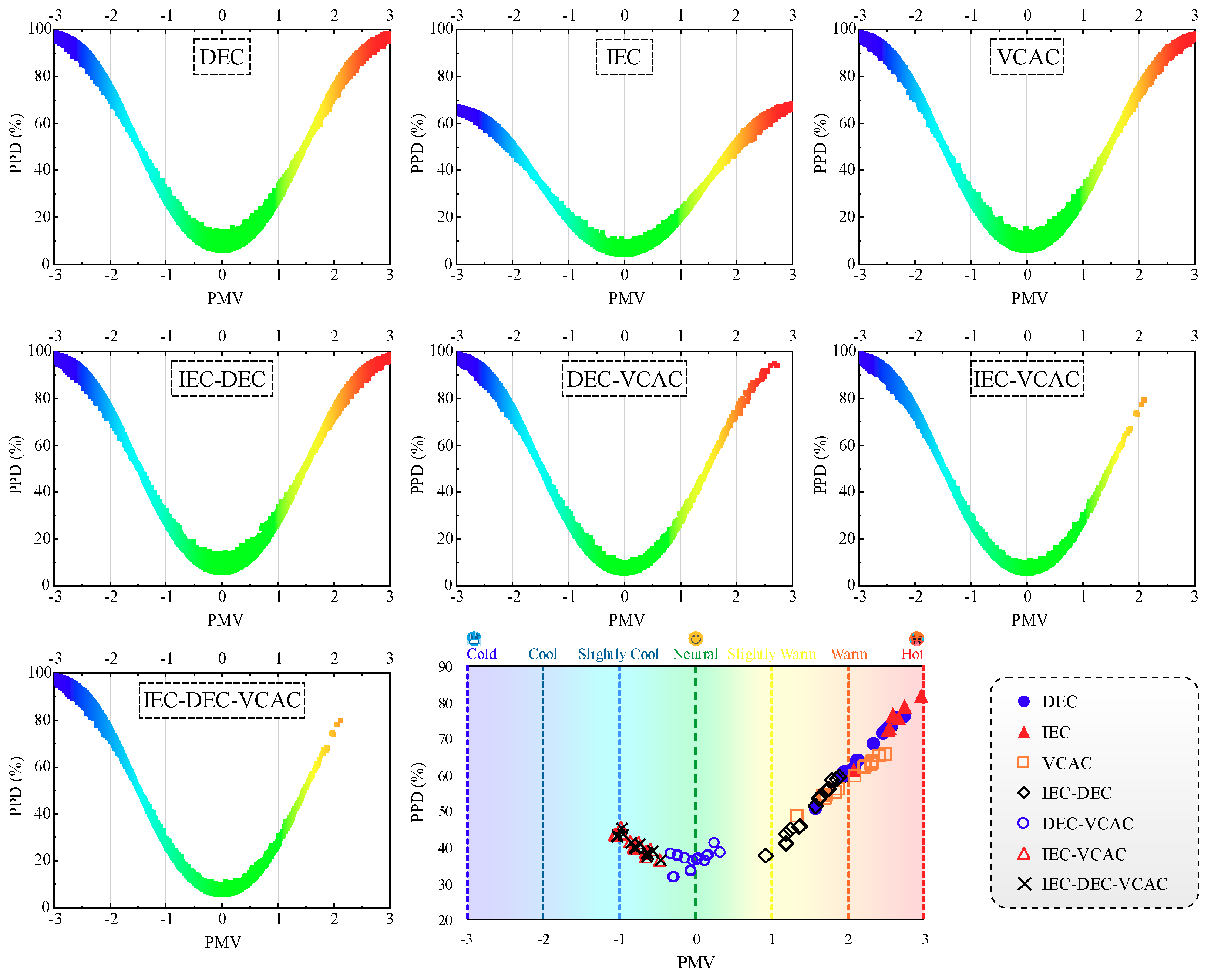
From the PMV and PPD point of view, hourly annual thermal comfort sensation resulted from the seven AC configurations and is presented in Figure 8. All the proposed AC configurations achieved thermal comfort at some point or another throughout the whole year. However, on 19 June, all the hybrid EC systems (i.e., DEC-VCAC, IEC-VCAC and IEC-DEC-VCAC) achieved neutral to slightly cool thermal sensation with PPD variation of 30% to 40% (Figure 8).
Performance of the seven AC systems based on the temperature gradient specifically in summer months (May, June, July, August) is presented in Figure 9. The IEC-DEC-VCAC system provided a temperature gradient of 10.9 °C (maximum) followed by 10.8 °C, 9.9 °C, 6.5 °C, 5.8 °C, 5.1 °C, and 3.2 °C (minimum) provided by IEC-VCAC, DEC-VCAC, IEC-DEC, VCAC, DEC, and IEC, respectively.
Performance of the seven AC configurations based on 1-day-averaged WBE for the climatic conditions of Multan (Pakistan) is presented in Figure 10. The IEC-DEC-VCAC system provided maximum WBE of 1.5 followed by IEC-VCAC i.e., 1.45, whereas, the standalone IEC system provided WBE of 0.5 (minimum). All the hybrid EC systems provided WBE of more than 1 due to pretreatment in EC stage and further compression at VCAC stage.
Variation in cooling capacity, work input and COP of the seven AC systems for summer months is presented in Figure 11a–c, respectively. The IEC-DEC-VCAC system provided the highest cooling capacity of 184 kW, followed by IEC-VCAC with 183.5 kW, whereas, the standalone IEC system provided the lowest cooling capacity of 63 kW (Figure 11a). The standalone EC systems provided the lowest work input of 20 to 30 kW compared to the VCAC system with 108 kW. It is important to note that IEC-DEC-VCAC provided relatively lower work input among the VCAC-based systems (Figure 11b). The standalone DEC system provided the highest COP of 4.5 followed by the IEC-DEC system with 4.2 due to relatively lower work input. It is also worth mentioning that the IEC-DEC-VCAC system provided a relatively higher COP of 2 among the VCAC-based systems (Figure 11c). VCAC-based AC systems resulted in low COP compared to the DEC and IEC-DEC systems due to higher work input at direct expansion stage (cooling coil). In addition, the details of annual electricity consumption (kWh) of the studied AC system configurations are provided in Figure S1 (Supplementary Materials).
Figure 12 depicts the annual water consumption by the seven AC systems. The IEC-DEC system resulted in the highest water consumption of 1256 m3 year−1 due to multistage EC systems followed by 1245, 1045, 1035, 704, and 697 m3 year−1 water consumption by the IEC-DEC-VCAC, DEC, DEC-VCAC, IEC, and IEC-VCAC systems, respectively. The standalone VCAC system consumed no water for cooling due to usage of air-cooled coil. All the hybrid systems provided relatively lower water consumption compared to their respective standalone systems.
Additionally, annual sensible and latent heat gains from different sources (i.e., surface conduction, windows, people, infiltration, and equipment and lights) into the building are presented in Figure 13. Surface conduction contributed the highest heat gain of 79.1% of the total heat gains. Heat gain from surface conduction is highest due to poor insulation of walls and roof during building construction in Pakistan. Based on the above discussions, it was concluded that the EC hybrid systems, especially the IEC-DEC-VCAC system provides a superior performance compared to other AC systems. Although COP of IEC-DEC-VCAC is lesser compared to other AC systems due to higher work input, this system provided the highest cooling capacity and WBE, and it can achieve the required conditions subject to a higher power consumption rate.
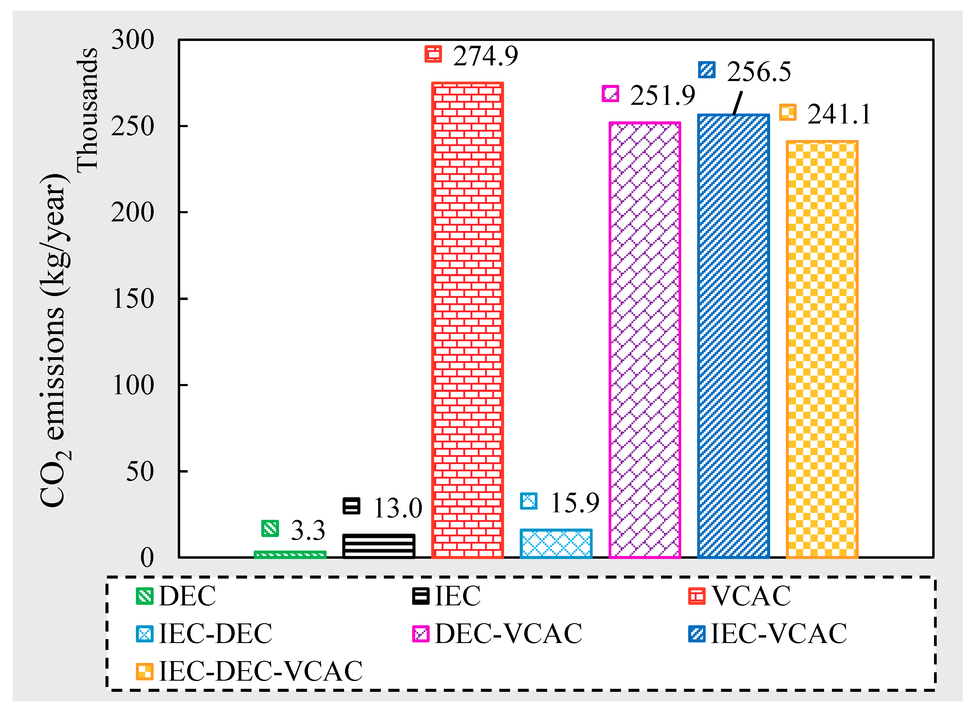
Annual greenhouse gas (CO2) emissions from the seven AC configurations is presented in Figure 14. CO2 emissions were obtained by multiplying the annual electricity consumption with the CO2 emission equivalent of 0.505 kgCO2 kWh−1 [85]. The DEC system emitted a minimum CO2 i.e., 332.8 kgCO2 year−1 due to the absence of a compressor followed by IEC, with 129.74 kgCO2 year−1. Among the VCAC-based systems, standalone VCAC system emitted the highest CO2 of 274,883 kgCO2 year−1. Moreover, the IEC-DEC-VCAC system emitted relatively the lowest CO2 of 241,134 kgCO2 year−1 among the VCAC hybrid systems.

5. Conclusions

The present study aimed to explore the optimum AC system configuration comprised of direct evaporative cooling (DEC), indirect evaporative cooling (IEC), and vapor compression AC (VCAC) systems for the climatic conditions of Multan (Pakistan). The study area lies in a warm desert (hot and dry) climate (BWh) class of Köppen climate classification. In this regard, building AC load and human thermal comfort requirements for the Agricultural Engineering Department building of Bahauddin Zakariya University, Multan, Pakistan, have been investigated. Standalone evaporative cooling and standalone vapor compression AC (VCAC) systems are commonly used in Pakistan. Therefore, the study proposed seven AC system configurations named as: DEC, IEC, VCAC, IEC-DEC, DEC-VCAC, IEC-VCAC, and IEC-DEC-VCAC. The systems were designed in DesignBuilder and simulated using EnergyPlus.
The IEC-DEC-VCAC system provided a temperature gradient of 21 °C (maximum) subject to a higher power consumption, whereas, standalone EC systems failed to compete. All three hybrid systems achieved neutral to slightly cool PMV thermal comfort with 30 to 40% PPD. The IEC-DEC-VCAC system provided the highest WBE and cooling capacity of 1.4 and 184 kW, respectively. On the other hand, the IEC system provided the lowest WBE and cooling capacity of 0.50 and 63 kW, respectively. The DEC system yielded the highest COP of 4.5, whereas the IEC-DEC-VCAC system provided a low COP of ~2.0 due to higher work input. The IEC-DEC-VCAC emitted an average annual CO2 of 241,134 kg of CO2 per year. Among the seven AC configurations, the standalone VCAC system resulted in the highest annual CO2 emissions i.e., 274,883 kg of CO2 per year. The standalone VCAC and hybrid IEC-VCAC & IEC-DEC-VCAC system configurations could achieve the desired human thermal comfort for the study area. However, the study concludes the hybrid IEC-DEC-VCAC as an optimum configuration (among the studied options) for building AC in Multan due to its better performance in terms of temperature gradient, thermal comfort, and CO2 emissions.

Supplementary Materials

The following are available online at https://www.mdpi.com/1996-1073/13/12/3061/s1, Figure S1: Annual electricity consumption (kWh) of different AC configurations.

Author Contributions

Conceptualization, S.N.; methodology, S.N. and H.A.; software, S.N. and H.A.; validation, H.A. and M.S.; formal analysis, S.N. and H.A.; investigation, S.N.; data curation, H.A.; writing—original draft preparation, S.N.; writing—review and editing, S.N., H.A. and M.S.; visualization, Z.M.K.; supervision, M.S. and Z.M.K.; project administration, M.S.; funding acquisition, M.S. All authors have read and agreed to the published version of the manuscript.

Funding

This research received no external funding.

Acknowledgments

All this work is part of the Ph.D. research of Shazia Noor (1st Author). This research work has been carried out in the Department of Agricultural Engineering, Bahauddin Zakariya University, Multan-Pakistan. This research was funded by Bahauddin Zakariya University, Multan-Pakistan under the Director Research/ORIC grant entitled “Development and performance evaluation of prototypes of direct and indirect evaporative cooling-based air conditioning systems” awarded to Principal Investigator Muhammad Sultan.

Conflicts of Interest

The authors declare no conflict of interest.

Nomenclature

TDifference between outside and supply air temperatures (°C)
ACAir–conditioning
ACHAir change per hour
AgSurface area of window (m2)
AHUAir handling unit
AsSurface area of wall (m2)
ASHRAEAmerican Society of Heating, Refrigerating and Air-Conditioning Engineers
cloClothing insulation unit (1 clo 0.155 m2 °C W−1)
ClothinsulClothing insulation (clo)
COPCoefficient of performance
CpSpecific heat capacity of air (1.005 kJ kg−1 K−1)
DACDesiccant air-conditioning system
DBTDry bulb temperature
DECDirect evaporative cooling system
DXDirect expansion
ESurface emissivity constant
ECEvaporative cooling systems
hconvConvective heat transfer coefficient (W m−2 °C−1)
heightHeight of human body (m)
hfgLatent heat of evaporation (kJ kg−1)
hinTotal enthalpy of air at inlet side (J kg−1)
hoHeat transfer coefficient (W m−2 °C)
houtTotal enthalpy of air at supply side (J kg−1)
HVACHeating, ventilation, and air-conditioning
IECIndirect evaporative cooling system
LfLoad factor of motor
mMass flow rate (kg s−1)
MECMaisotsenko-cycle based evaporative cooling
MetMetabolic rate of body per area (W m−2)
minAir infiltration inflow rate (m3 h−1)
MRTMean radiant temperature (°C)
PaVapor pressure of air (Pa)
PfloorFloor perimeter (m)
PMVPredicted mean vote
PPDPredicted percentage of dissatisfaction (%)
PrPower of motor (W)
QCooling capacity (kW)
QcHeat transfer through center of glazing (W)
QeHeat transfer through edge of glazing (W)
QextHeat gains through exterior surfaces (W)
QfHeat transfer through frame of glazing (W)
QglazingHeat gains through windows (W)
QhbHeat gains through human body (W)
Ql,iLatent heat gains through air infiltration (W)
QlatLatent heat gains from skin and lungs (W)
QlatentTotal latent energy transfer (W)
QmHeat gains through fan motor (W)
QnetTotal cooling capacity (W)
Qs,iSensible heat gains through air infiltration (W)
QsensSensible heat gains from skin and lungs (W)
QsensibleTotal sensible energy transfer (W)
qsolarIncident solar radiation (W m−2)
QspHeat gains through floor perimeter (W)
QwallHeat gains through walls (W)
QworkHeat loss from working human body (W m−2)
RcThermal resistance of clothes (m2 °C W−1)
rcbRatio of clothed to naked body
TaAmbient air temperature (°C)
TairTemperature of conditioned air (°C)
TclothTemperature of clothes (°C)
TinInside air temperature (°C)
TOAOutside air temperature (°C)
ToutOutside air temperature (°C)
TsSurface air temperature (°C)
Ts–aSol-air temperature (°C)
TSASupply air temperature (°C)
TsurMean temperature of surrounding surfaces (°C)
uVolumetric flow of air (m3 s−1)
uairVelocity of air flow (m s−1)
UfUtilization factor
UfloorOverall heat transfer coefficient of floor (W m−1 °C−1)
UgOverall heat transfer coefficient of glazing (W m−1 °C−1)
UwallOverall heat transfer coefficient (W m−1 °C−1)
VBuilding volume (m3)
VCACVapor compression air–conditioning system
WWork input (kW)
WBEWet-bulb effectiveness
WBTWet-bulb temperature
XinInside air humidity ratio (g g−1)
XminMinimum of inlet and outlet air humidity ratios (kg/kg)
XoutOutside air humidity ratio (g g−1)
αsolarSolar absorptivity constant
εwbWet–bulb effectiveness (-)
ηmEfficiency of motor
ρairDensity of air (kg m−3)
φSolar incident angle relative to the latitude

References

  1. Wang, S.; Tang, R. Supply-based feedback control strategy of air-conditioning systems for direct load control of buildings responding to urgent requests of smart grids. Appl. Energy 2017, 201, 419–432. [Google Scholar] [CrossRef]
  2. Mahmood, M.H.; Sultan, M.; Miyazaki, T.; Koyama, S.; Maisotsenko, V.S. Overview of the Maisotsenko cycle—A way towards dew point evaporative cooling. Renew. Sustain. Energy Rev. 2016, 66, 537–555. [Google Scholar] [CrossRef]
  3. Sultan, M.; Miyazaki, T.; Saha, B.B.; Koyama, S. Steady-state investigation of water vapor adsorption for thermally driven adsorption based greenhouse air-conditioning system. Renew. Energy 2016, 86, 785–795. [Google Scholar] [CrossRef]
  4. Cheng, F.; Li, Y.; Zhang, X.; Li, X. Effect of different absorbents on actual performance of the absorption air-conditioning system based on capacitive deionization regeneration method. Appl. Therm. Eng. 2020, 172, 115130. [Google Scholar] [CrossRef]
  5. International Energy Agency (IEA). Online Data Services; International Energy Agency (IEA): Paris, France, 2017. [Google Scholar]
  6. Afroz, Z.; Shafiullah, G.M.; Urmee, T.; Higgins, G. Modeling techniques used in building HVAC control systems: A review. Renew. Sustain. Energy Rev. 2018, 83, 64–84. [Google Scholar] [CrossRef]
  7. Yang, Z.; Ghahramani, A.; Becerik-Gerber, B. Building occupancy diversity and HVAC (heating, ventilation, and air conditioning) system energy efficiency. Energy 2016, 109, 641–649. [Google Scholar] [CrossRef] [Green Version]
  8. Kojok, F.; Fardoun, F.; Younes, R.; Outbib, R. Hybrid cooling systems: A review and an optimized selection scheme. Renew. Sustain. Energy Rev. 2016, 65, 57–80. [Google Scholar] [CrossRef]
  9. Duan, Z.; Zhan, C.; Zhang, X.; Mustafa, M.; Zhao, X.; Alimohammadisagvand, B.; Hasan, A. Indirect evaporative cooling: Past, present and future potentials. Renew. Sustain. Energy Rev. 2012, 16, 6823–6850. [Google Scholar] [CrossRef]
  10. Duan, Z.; Zhao, X.; Zhan, C.; Dong, X.; Chen, H. Energy saving potential of a counter-flow regenerative evaporative cooler for various climates of China: Experiment-based evaluation. Energy Build. 2017, 148, 199–210. [Google Scholar] [CrossRef]
  11. Liu, Y.; Yang, X.; Li, J.; Zhao, X. Energy savings of hybrid dew-point evaporative cooler and micro-channel separated heat pipe cooling systems for computer data centers. Energy 2018, 163, 629–640. [Google Scholar] [CrossRef] [Green Version]
  12. Matsui, K.; Thu, K.; Miyazaki, T. A Hybrid Power Cycle using an Inverted Brayton Cycle with an Indirect Evaporative Device for Waste-heat Recovery. Appl. Therm. Eng. 2020, 115029. [Google Scholar] [CrossRef]
  13. Farmahini-Farahani, M.; Delfani, S.; Esmaeelian, J. Exergy analysis of evaporative cooling to select the optimum system in diverse climates. Energy 2012, 40, 250–257. [Google Scholar] [CrossRef]
  14. Lin, J.; Bui, D.T.; Wang, R.; Chua, K.J. On the exergy analysis of the counter-flow dew point evaporative cooler. Energy 2018, 165, 958–971. [Google Scholar] [CrossRef]
  15. Alklaibi, A.M. Experimental and theoretical investigation of internal two-stage evaporative cooler. Energy Convers. Manag. 2015, 95, 140–148. [Google Scholar] [CrossRef]
  16. Fikri, B.; Sofia, E.; Putra, N. Experimental analysis of a multistage direct-indirect evaporative cooler using a straight heat pipe. Appl. Therm. Eng. 2020, 171, 115133. [Google Scholar] [CrossRef]
  17. Khalajzadeh, V.; Farmahini-Farahani, M.; Heidarinejad, G. A novel integrated system of ground heat exchanger and indirect evaporative cooler. Energy Build. 2012, 49, 604–610. [Google Scholar] [CrossRef]
  18. Chauhan, S.S.; Rajput, S.P.S. Experimental analysis of an evaporative–vapour compression based combined air conditioning system for required comfort conditions. Appl. Therm. Eng. 2017, 115, 326–336. [Google Scholar] [CrossRef]
  19. Duan, Z.; Zhao, X.; Liu, J.; Zhang, Q. Dynamic simulation of a hybrid dew point evaporative cooler and vapour compression refrigerated system for a building using EnergyPlus. J. Build. Eng. 2019, 21, 287–301. [Google Scholar] [CrossRef]
  20. Zhou, S.; Gong, L.; Liu, X.; Shen, S. Mathematical modeling and performance analysis for multi-effect evaporation/multi-effect evaporation with thermal vapor compression desalination system. Appl. Therm. Eng. 2019, 159, 113759. [Google Scholar] [CrossRef]
  21. Rostamzadeh, H.; Rostamzadeh, J.; Matin, P.S.; Ghaebi, H. Novel dual-loop bi-evaporator vapor compression refrigeration cycles for freezing and air-conditioning applications. Appl. Therm. Eng. 2018, 138, 563–582. [Google Scholar] [CrossRef]
  22. Hong, H.; Li, W.; Gu, C. Performance study on a mechanical vapor compression evaporation system driven by Roots compressor. Int. J. Heat Mass Transf. 2018, 125, 343–349. [Google Scholar] [CrossRef]
  23. Kim, M.-H.; Jeong, J.-W. Cooling performance of a 100% outdoor air system integrated with indirect and direct evaporative coolers. Energy 2013, 52, 245–257. [Google Scholar] [CrossRef]
  24. Hasan, A. Indirect evaporative cooling of air to a sub-wet bulb temperature. Appl. Therm. Eng. 2010, 30, 2460–2468. [Google Scholar] [CrossRef]
  25. Delfani, S.; Esmaeelian, J.; Pasdarshahri, H.; Karami, M. Energy saving potential of an indirect evaporative cooler as a pre-cooling unit for mechanical cooling systems in Iran. Energy Build. 2010, 42, 2169–2176. [Google Scholar] [CrossRef]
  26. Heidarinejad, G.; Bozorgmehr, M.; Delfani, S.; Esmaeelian, J. Experimental investigation of two-stage indirect/direct evaporative cooling system in various climatic conditions. Build. Environ. 2009, 44, 2073–2079. [Google Scholar] [CrossRef]
  27. Chiesa, G.; Huberman, N.; Pearlmutter, D. Geo-climatic potential of direct evaporative cooling in the Mediterranean Region: A comparison of key performance indicators. Build. Environ. 2019, 151, 318–337. [Google Scholar] [CrossRef]
  28. Sohani, A.; Sayyaadi, H. Thermal comfort based resources consumption and economic analysis of a two-stage direct-indirect evaporative cooler with diverse water to electricity tariff conditions. Energy Convers. Manag. 2018, 172, 248–264. [Google Scholar] [CrossRef]
  29. Jaber, S.; Ezzat, A.W. Investigation of energy recovery with exhaust air evaporative cooling in ventilation system. Energy Build. 2017, 139, 439–448. [Google Scholar] [CrossRef]
  30. Aparicio-Ruiz, P.; Schiano-Phan, R.; Salmerón-Lissén, J.M. Climatic applicability of downdraught evaporative cooling in the United States of America. Build. Environ. 2018, 136, 162–176. [Google Scholar] [CrossRef] [Green Version]
  31. Sultan, M.; El-Sharkawy, I.I.; Miyazaki, T.; Saha, B.B.; Koyama, S.; Maruyama, T.; Maeda, S.; Nakamura, T. Water vapor sorption kinetics of polymer based sorbents: Theory and experiments. Appl. Therm. Eng. 2016, 106, 192–202. [Google Scholar] [CrossRef]
  32. Hanif, S.; Sultan, M.; Miyazaki, T. Effect of relative humidity on thermal conductivity of zeolite-based adsorbents: Theory and experiments. Appl. Therm. Eng. 2019, 150, 11–18. [Google Scholar] [CrossRef]
  33. Shabir, F.; Sultan, M.; Miyazaki, T.; Saha, B.B.; Askalany, A.; Ali, I.; Zhou, Y.; Ahmad, R.; Shamshiri, R.R. Recent updates on the adsorption capacities of adsorbent-adsorbate pairs for heat transformation applications. Renew. Sustain. Energy Rev. 2020, 119, 109630. [Google Scholar] [CrossRef]
  34. Kim, M.-H.; Yoon, D.-S.; Kim, H.-J.; Jeong, J.-W. Retrofit of a liquid desiccant and evaporative cooling-assisted 100% outdoor air system for enhancing energy saving potential. Appl. Therm. Eng. 2016, 96, 441–453. [Google Scholar] [CrossRef]
  35. Ham, S.-W.; Lee, S.-J.; Jeong, J.-W. Operating energy savings in a liquid desiccant and dew point evaporative cooling-assisted 100% outdoor air system. Energy Build. 2016, 116, 535–552. [Google Scholar] [CrossRef]
  36. Cuce, P.M. Thermal performance assessment of a novel liquid desiccant-based evaporative cooling system: An experimental investigation. Energy Build. 2017, 138, 88–95. [Google Scholar] [CrossRef]
  37. Cho, H.-J.; Jeong, J.-W. Evaluation of thermal comfort in an office building served by a liquid desiccant-assisted evaporative cooling air-conditioning system. Energy Build. 2018, 172, 361–370. [Google Scholar] [CrossRef]
  38. Kashif Shahzad, M.; Qadar Chaudhary, G.; Ali, M.; Ahmed Sheikh, N.; Shahid Khalil, M.; Rashid, T.U. Experimental evaluation of a solid desiccant system integrated with cross flow Maisotsenko cycle evaporative cooler. Appl. Therm. Eng. 2018, 128, 1476–1487. [Google Scholar] [CrossRef]
  39. Sultan, M.; El-Sharkawy, I.I.; Miyazaki, T.; Saha, B.B.; Koyama, S. An overview of solid desiccant dehumidification and air conditioning systems. Renew. Sustain. Energy Rev. 2015, 46, 16–29. [Google Scholar] [CrossRef]
  40. Sultan, M.; Mahmood, M.H.; Miyazaki, T.; Koyama, S.; Khan, Z.M. Close and open cycle adsorption kinetics: Development of correlation for desiccant air-conditioning. J. Eng. Appl. Sci. 2016, 35, 59–66. [Google Scholar]
  41. Mahmood, M.H.; Sultan, M.; Miyazaki, T. Experimental evaluation of desiccant dehumidification and air-conditioning system for energy-efficient storage of dried fruits. Build. Serv. Eng. Res. Technol. 2019, 0143624419893660. [Google Scholar] [CrossRef]
  42. Sultan, M.; Miyazaki, T.; Mahmood, M.; Mahmood Khan, Z. Solar assisted evaporative cooling based passive air-conditioning system for agricultural and livestock applications. J. Eng. Sci. Technol. 2018, 13, 693–703. [Google Scholar]
  43. Sultan, M.; Miyazaki, T. Energy-efficient air-conditioning systems for nonhuman applications. In Refrigeration; Ekren, O., Ed.; InTech: London, UK, 2017. [Google Scholar]
  44. Sultan, M.; Miyazaki, T.; Koyama, S. Optimization of adsorption isotherm types for desiccant air-conditioning applications. Renew. Energy 2018, 121, 441–450. [Google Scholar] [CrossRef]
  45. Sultan, M.; Miyazaki, T.; Koyama, S.; Khan, Z.M. Performance evaluation of hydrophilic organic polymer sorbents for desiccant air-conditioning applications. Adsorpt. Sci. Technol. 2018, 36, 311–326. [Google Scholar] [CrossRef] [Green Version]
  46. Kashif, M.; Niaz, H.; Sultan, M.; Miyazaki, T.; Feng, Y.; Usman, M.; Shahzad, M.W.; Niaz, Y.; Waqas, M.M.; Ali, I. Study on Desiccant and Evaporative Cooling Systems for Livestock Thermal Comfort: Theory and Experiments. Energies 2020, 13, 2675. [Google Scholar] [CrossRef]
  47. Kottek, M.; Grieser, J.; Beck, C.; Rudolf, B.; Rubel, F. World map of the Köppen-Geiger climate classification updated. Meteorol. Z. 2006, 15, 259–263. [Google Scholar] [CrossRef]
  48. Niaz, H.; Sultan, M.; Khan, A.; Mahmood, M.; Feng, Y.; Mahmood Khan, Z.; Niaz, E.D.Y.; Ali, I.; Imran, M. Study on evaporative cooling assisted desiccant air-conditioning system for livestock application in Pakistan. Fresenius Environ. Bull. 2019, 28, 8623–8633. [Google Scholar]
  49. Chen, J.; Ding, R.; Li, Y.; Lin, X.; Chen, Y.; Luo, X.; Yang, Z. Application of a vapor–liquid separation heat exchanger to the air conditioning system at cooling and heating modes. Int. J. Refrig. 2019, 100, 27–36. [Google Scholar] [CrossRef]
  50. ASHRAE Handbook of Fundamentals. Am. Soc. Heating, Refrig; Air-Conditioning Eng. Inc.: Atlanta, GA, USA, 2013.
  51. Havenith, G.; Kuklane, K.; Fan, J.; Hodder, S.; Ouzzahra, Y.; Lundgren, K.; Au, Y.; Loveday, D. A database of static clothing thermal insulation and vapor permeability values of non-Western ensembles for use in ASHRAE standard 55, ISO 7730, and ISO 9920. ASHRAE Trans. 2015, 121, 197–215. [Google Scholar]
  52. Designbuilder Software Limited. DesignBuilder 6.1; Designbuilder Software Limited: Stroud, UK, 2020. [Google Scholar]
  53. U.S. Department of Energy (DOE); National Renewable Energy Laboratory (NREL). EnergyPlus 9.3; U.S. Department of Energy (DOE): Washington, DC, USA; National Renewable Energy Laboratory (NREL): Golden, CO, USA, 2020.
  54. Shen, B.; New, J.; Baxter, V. Air source integrated heat pump simulation model for EnergyPlus. Energy Build. 2017, 156, 197–206. [Google Scholar] [CrossRef]
  55. Kang, W.H.; Lee, J.M.; Yeon, S.H.; Park, M.K.; Kim, C.H.; Lee, J.H.; Moon, J.W.; Lee, K.H. Modeling, calibration, and sensitivity analysis of direct expansion AHU-Water source VRF system. Energy 2020, 199, 117435. [Google Scholar] [CrossRef]
  56. Seo, B.; Yoon, Y.B.; Yu, B.H.; Cho, S.; Lee, K.H. Comparative analysis of cooling energy performance between water-cooled VRF and conventional AHU systems in a commercial building. Appl. Therm. Eng. 2020, 170, 114992. [Google Scholar] [CrossRef]
  57. Naderi, E.; Sajadi, B.; Behabadi, M.A.; Naderi, E. Multi-objective simulation-based optimization of controlled blind specifications to reduce energy consumption, and thermal and visual discomfort: Case studies in Iran. Build. Environ. 2020, 169, 106570. [Google Scholar] [CrossRef]
  58. Im, P.; Joe, J.; Bae, Y.; New, J.R. Empirical validation of building energy modeling for multi-zones commercial buildings in cooling season. Appl. Energy 2020, 261, 114374. [Google Scholar] [CrossRef]
  59. Salata, F.; Ciancio, V.; Dell’Olmo, J.; Golasi, I.; Palusci, O.; Coppi, M. Effects of local conditions on the multi-variable and multi-objective energy optimization of residential buildings using genetic algorithms. Appl. Energy 2020, 260, 114289. [Google Scholar] [CrossRef]
  60. Rosso, F.; Ciancio, V.; Dell’Olmo, J.; Salata, F. Multi-objective optimization of building retrofit in the Mediterranean climate by means of genetic algorithm application. Energy Build. 2020, 216, 109945. [Google Scholar] [CrossRef]
  61. Wang, H.; Lu, W.; Wu, Z.; Zhang, G. Parametric analysis of applying PCM wallboards for energy saving in high-rise lightweight buildings in Shanghai. Renew. Energy 2020, 145, 52–64. [Google Scholar] [CrossRef]
  62. Qiu, C.; Yi, Y.K.; Wang, M.; Yang, H. Coupling an artificial neuron network daylighting model and building energy simulation for vacuum photovoltaic glazing. Appl. Energy 2020, 263, 114624. [Google Scholar] [CrossRef]
  63. Ascione, F.; Bianco, N.; Iovane, T.; Mauro, G.M.; Napolitano, D.F.; Ruggiano, A.; Viscido, L. A real industrial building: Modeling, calibration and Pareto optimization of energy retrofit. J. Build. Eng. 2020, 29, 101186. [Google Scholar] [CrossRef]
  64. Troup, L.N.; Fannon, D.J.; Eckelman, M.J. Spatio-temporal changes among site-to-source conversion factors for building energy modeling. Energy Build. 2020, 213, 109832. [Google Scholar] [CrossRef]
  65. Martin, M.; Wong, N.H.; Hii, D.J.C.; Ignatius, M. Comparison between simplified and detailed EnergyPlus models coupled with an urban canopy model. Energy Build. 2017, 157, 116–125. [Google Scholar] [CrossRef]
  66. Qin, H.; Pan, W. Energy use of subtropical high-rise public residential buildings and impacts of energy saving measures. J. Clean. Prod. 2020, 254, 120041. [Google Scholar] [CrossRef]
  67. Crawley, D.B.; Hand, J.W.; Kummert, M.; Griffith, B.T. Contrasting the capabilities of building energy performance simulation programs. Build. Environ. 2008, 43, 661–673. [Google Scholar] [CrossRef] [Green Version]
  68. Bojić, M.; Nikolić, N.; Nikolić, D.; Skerlić, J.; Miletić, I. Toward a positive-net-energy residential building in Serbian conditions. Appl. Energy 2011, 88, 2407–2419. [Google Scholar] [CrossRef]
  69. Woods, J.; Bonnema, E. Regression-based approach to modeling emerging HVAC technologies in EnergyPlus: A case study using a Vuilleumier-cycle heat pump. Energy Build. 2019, 186, 195–207. [Google Scholar] [CrossRef]
  70. Anđelković, A.S.; Mujan, I.; Dakić, S. Experimental validation of a EnergyPlus model: Application of a multi-storey naturally ventilated double skin façade. Energy Build. 2016, 118, 27–36. [Google Scholar] [CrossRef]
  71. Cho, H.M.; Wi, S.; Chang, S.J.; Kim, S. Hygrothermal properties analysis of cross-laminated timber wall with internal and external insulation systems. J. Clean. Prod. 2019, 231, 1353–1363. [Google Scholar] [CrossRef]
  72. Karimi, M.S.; Fazelpour, F.; Rosen, M.A.; Shams, M. Comparative study of solar-powered underfloor heating system performance in distinctive climates. Renew. Energy 2019, 130, 524–535. [Google Scholar] [CrossRef]
  73. Ceballos-Fuentealba, I.; Álvarez-Miranda, E.; Torres-Fuchslocher, C.; del Campo-Hitschfeld, M.L.; Díaz-Guerrero, J. A simulation and optimisation methodology for choosing energy efficiency measures in non-residential buildings. Appl. Energy 2019, 256, 113953. [Google Scholar] [CrossRef]
  74. Zhang, A.; Bokel, R.; van den Dobbelsteen, A.; Sun, Y.; Huang, Q.; Zhang, Q. An integrated school and schoolyard design method for summer thermal comfort and energy efficiency in Northern China. Build. Environ. 2017, 124, 369–387. [Google Scholar] [CrossRef]
  75. Abdeen, A.; Serageldin, A.A.; Ibrahim, M.G.E.; El-Zafarany, A.; Ookawara, S.; Murata, R. Experimental, analytical, and numerical investigation into the feasibility of integrating a passive Trombe wall into a single room. Appl. Therm. Eng. 2019, 154, 751–768. [Google Scholar] [CrossRef]
  76. Venkateswara Rao, V.; Datta, S.P. A feasibility assessment of single to multi/hybrid evaporative coolers for building air-conditioning across diverse climates in India. Appl. Therm. Eng. 2020, 168, 114813. [Google Scholar] [CrossRef]
  77. Thermal Energy System Specialists LLC. TRNSYS 17; Thermal Energy System Specialists LLC: Madison, WI, USA, 2019. [Google Scholar]
  78. ASHRAE Standards Committee. ANSI/ASHRAE Standard 143-2007, Method of Test for Rating Indirect Evaporative Coolers; ASHRAE Standards Committee: Atlanta, GA, USA, 2007. [Google Scholar]
  79. DuBois, D.F. A formula to estimate the approximate surface area if height and body mass be known. Arch. Intern. Med. 1916, 17, 863–871. [Google Scholar] [CrossRef] [Green Version]
  80. Cengel, Y. Heat and Mass Transfer: Fundamentals and Applications; McGraw-Hill Higher Education: New York, NY, USA, 2014; ISBN 0077654765. [Google Scholar]
  81. Kreider, J.F.; Curtiss, P.S.; Rabl, A. Heating and Cooling of Buildings: Design for Efficiency; CRC Press: Boca Raton, FL, USA, 2009; ISBN 1439882509. [Google Scholar]
  82. ISO. ISO 7730, Ergonomics of the Thermal Environment—Analytical Determination and Interpretation of Thermal Comfort Using Calculation of the PMV and PPD Indices and Local Thermal Comfort Criteria; ISO: Geneva, Switzerland, 2005. [Google Scholar]
  83. Raza, H.M.U. Investigation of Evaporative Cooling Based Low-Cost Air-Conditioning Technologies for Pakistan. Master’s Thesis (Hons.), Bahauddin Zakariya University, Multan, Pakistan, 2018. [Google Scholar]
  84. Teitelbaum, E.; Jayathissa, P.; Miller, C.; Meggers, F. Design with Comfort: Expanding the psychrometric chart with radiation and convection dimensions. Energy Build. 2020, 209, 109591. [Google Scholar] [CrossRef]
  85. Yousuf, I.; Ghumman, A.R.; Hashmi, H.N.; Kamal, M.A. Carbon emissions from power sector in Pakistan and opportunities to mitigate those. Renew. Sustain. Energy Rev. 2014, 34, 71–77. [Google Scholar] [CrossRef]
Figure 1. Köppen–Geiger climate classification map of Pakistan, reproduced from [47].
Energies 13 03061 g001
Figure 2. Schematic illustrations and the corresponding psychrometric behavior for seven proposed configurations of EC and VCAC systems: (a) DEC, (b) IEC, (c) VCAC, (d) IEC-DEC, (e) DEC-VCAC, (f) IEC-VCAC, and (g) IEC-DEC-VCAC.
Energies 13 03061 g002
Figure 3. 3-D model for the studied building of the Agricultural Engineering Department of Bahauddin Zakariya University, Multan, Pakistan: (a) constructed view, and (b) rendered view.
Energies 13 03061 g003
Figure 4. Wet-bulb effectiveness determined from lab-scale DEC and IEC experimental apparatus for summer climatic conditions of Multan [83].
Energies 13 03061 g004
Figure 5. Performance evaluation on monthly basis for the proposed seven AC system configurations using annual climatic data.
Energies 13 03061 g005
Figure 6. Performance evaluation on hourly basis for the proposed seven AC system configurations using climatic data of 19 June.
Energies 13 03061 g006
Figure 7. Profile of thermal comfort correlating with MRT for all the seven AC configurations.
Energies 13 03061 g007
Figure 8. Annual variation of thermal comfort indices of the seven AC configurations.
Energies 13 03061 g008
Figure 9. Profile of temperature gradient in typical summer months of Multan.
Energies 13 03061 g009
Figure 10. One-day-averaged variation of wet-bulb effectiveness of the seven AC configurations.
Energies 13 03061 g010
Figure 11. Variation in (a) Cooling capacity, (b) work input, and (c) COP of the seven AC configurations in summer.
Energies 13 03061 g011
Figure 12. Annual end-use water consumption for cooling by the seven AC configurations.
Energies 13 03061 g012
Figure 13. Annual energy nexus–sensible heat gains from different sources in the building.
Energies 13 03061 g013
Figure 14. Annual CO2 emissions of the proposed cooling systems in the building.
Energies 13 03061 g014
Table 1. Simulation inputs and building construction characteristics.
Construction TypePropertiesValues
Layer 1 (outer wall)Brickwork outer0.1016 m
Layer 2 (outer wall)Cement/plaster/mortar—cement0.0127 m
Layer 3 (outer wall)Brickwork inner0.1016 m
Layer 4 (outer wall)Cement/plaster/mortar—cement0.0127 m
Medium weight flat roof Layer 18 in. concrete0.2032 m
Medium weight flat roof Layer 2Cement/plaster/mortar—cement0.0127 m
Floor (Layer 1)Cast concrete (dense)0.127 m
Floor (Layer 2)2 in. concrete0.0508 m
DoorsLightweight plywood0.0381 m
Glazing/ windowGeneric clear0.003 m
Fixed height/widthHeight1.83 m
-Width1.52 m
Frame type/widthAluminum0.04 m
Total building area3251.74 m2
Total conditioned area847.5 m2
Density Inputs
Lighting power densityNormalized (varies zone to zone)2.5 W m−2
-Radiant fraction0.72
-Visible fraction0.18
OccupancyDensity (varies zone to zone)0.295/conditioned area
Workday scheduleOn at08:00 am
-Off at04:00 pm
Clothing (Shalwar, Kameez) [50,51]Winter1.145 clo
(1 clo = 0.155 m2 °C W−1)Summer0.775 clo
Air Handling Unit (AHU)
FanTotal efficiency75%
Fan typeConstant air volume (CAV)
AHU typeCentral air-conditioning system
Motor efficiency85%
Fan pressure600 Pa
COP of VCAC3
Thermostat and humidistat setpoint24 °C and 60%
Direct research specialDesign wet-bulb effectiveness (WBE)0.90
Indirect research specialDesign WBE0.605