Article

Controlling the Deformation of a Small Coal Pillar Retaining Roadway by Non-Penetrating Directional Pre-Splitting Blasting with a Deep Hole: A Case Study in Wangzhuang Coal Mine

State Key Laboratory for Geomechanics and Deep Underground Engineering, School of Mechanics and Civil Engineering, China University of Mining & Technology, Xuzhou 221116, China
*
Authors to whom correspondence should be addressed.
Energies 2020, 13(12), 3084; https://doi.org/10.3390/en13123084
Submission received: 16 May 2020 / Revised: 9 June 2020 / Accepted: 12 June 2020 / Published: 15 June 2020

Abstract

:
In longwall mining of coal mines, the large deformation of small pillar retaining roadways creates difficulties for the safe and efficient retreating of the mining panel. Based on the engineering background of a small coal pillar retaining roadway in Wangzhuang coal mine, pressure relief technology for non-penetrating directional pre-splitting blasting with a deep hole ahead was proposed. The influence of the non-penetrating fracture length on the pre-splitting effect was studied by numerical simulation. The results showed that the vertical stress in the coal pillar center, the small pillar retaining roadway deformation, and the energy accumulation on the pillar decreased with an increase in the non-penetrating fracture length. The vertical stress at the working face end increased with an increase in the non-penetrating fracture length. The field application and monitoring results indicated that non-penetrating directional pre-splitting blasting could effectively control the deformation of small pillar retaining roadways. The roof-to-floor and rib-to-rib maximum convergences of the 6208 tail entry were reduced by 53.66% and 52.62%, respectively, compared to the results with no blasting. The roadway section met the demands of mining panel high-efficiency retreating, thereby demonstrating the rationality of the technical and numerical simulation results. The research results shed light on the improvement of small coal pillar retaining roadway maintenance theory and technology.

Graphical Abstract

1. Introduction

The total length of the roadways on both sides of the mining panels in Chinese underground coal mines can be up to several million meters. These roadways have been maintained by the method of retaining a coal pillar for a long period of time [1,2,3]. The method of retaining a coal pillar for roadway maintenance is characterized by setting a coal pillar of a certain width between the upper section head entry and the lower section tail entry [4], as shown in Figure 1. Roadway retention with a small coal pillar is widely used in coal mines due to the high recovery rate of coal resources [5,6]. However, because of the weak bearing capacity of small coal pillars and the repeated mining influence on both sides of the mining panels, the convergence deformation of the roadway can increase dramatically [7,8,9]. Moreover, the stability of a small coal pillar is difficult to control. Thus, safety issues are prominent, and maintenance costs are high.
Considering the large deformation of small coal pillar roadways, the current research mainly focuses on coal pillar stability and reinforced supports. Peng et al. [10] studied the layout and support method of coal pillar in longwall mining, analyzed the stress distribution on coal pillar, and summarized the reinforcement methods of roadway, including bolts, anchor cables, steel beams with hydraulic prop, wood crib, and grouting, to improve the bearing capacity of roadway surrounding rocks and reduce roadway deformation. Liu et al. [11] analyzed the instability mechanism of coal pillar by basic measurement scale-borehole comprehensive parameter method, proposed measures for controlling coal pillar stability, namely roof pre-cutting, re-anchoring, and long and short injection. Li et al. [12] studied the basic mechanical structure of coal pillar and the characteristics of its weakening failure, evaluated the support effects of high pre-tightening force and strong anchorage. Zhang et al. [13] investigated the inner deformation and residual loading behavior of the small coal pillar, put forward tensing the collapsed zone, controlling the fracture zone and grouting the stable zone. Wattimena et al. [14] developed the logistic regression model for predicting the probability of stability of a coal pillar for given geometry (width to height ratio) and stress condition (strength to stress ratio), constructed the coal pillar stability chart. Qin et al. [15] presented a theoretical framework that explicitly links observation data of roof settlement or coal-pillar deformation and AE with a nonlinear dynamical model, used a nonlinear dynamical model to study the physical prediction of coal bumps. However, with the current increase in mining intensity, it is difficult to meet the requirements of large deformation maintenance by using reinforced supports in small coal pillar roadways.
Blasting is widely used in coal mines [16], mainly used for roadway excavation and rock breaking. Much research has been done on blasting fractures and many significant results have been obtained. Xu et al. [17] constructed the damage degree model of a blasting pressure relief zone, determined the damage degree of the blasting crushing zone. Wang [18] analyzed the dynamic fracture effect of blasting detonation crack of different charge structures, and examined the directional fracture-controlled blasting mechanism of slotted cartridge. Yue et al. [19] studied the crack propagation behaviors of polymethyl methacrylate material with double holes under the directional controlled blasting, analyzed the fracture mechanisms of the double blasting holes. Ma et al. [20] implemented the Johnson–Holmquist (J-H) material model into the commercial software LS-DYNA through user-subroutines to simulate the blasting-induced rock fractures, explored influences of the key parameters in smooth blasting. Jayasinghe et al. [21] presented a 3D coupled Smoothed Particle Hydrodynamics (SPH) and Finite Element Method (FEM) model to investigate the extent of damage zone and fracture patterns in rock due to blasting. Yang et al. [22] studied the stress distribution around a borehole under high static stress, analyzed the crack propagation behavior related to slit charge blasting under high static stress conditions. However, research on blasting fractures is currently focused on fracture propagation, and there are few studies on the control of blasting fractures propagation in the coal mines’ filed application.
In the gob side entry retaining by roof cutting, the roadway roof is cut off by directional blasting, and the roof fully collapses to form the gob-side support body beside the roadway. He et al. [23] introduced an innovative non-pillar longwall mining approach, proposed a directional roof fracturing technique to contribute to gob roof caving, researched the evolutionary laws of the roof structure and stresses. Wang et al. [24] established a short cantilever beam mechanical model using energy theory methods, explored the relationship between the roof deformation and main influence parameters. Sun et al. [25] proposed the idea of preventing rock burst by the Gob-side entry retaining through precut overhanging hard roof method, studied the stress distribution characteristics of conventional mining and precut overhanging hard roof mining. Gao et al. [26] proposed a directional roof split blasting technique and tested in a thick coal seam, and studied the meso- and macroeffects of this technique on the entry stabilities in relation to the damage evolution, stress distribution and surroundings deformation. Wang et al. [27] introduced the concept and key techniques of no-pillar mining with automatically formed gob-side entry retaining, performed the field engineering test. Continuous penetrating fractures are formed in the roof by directional pre-splitting blasting in the gob side entry retaining, which makes the roof fully collapse to form the gob-side support body beside the roadway. However, continuous fractures may cause serious deformation of the working face end, producing great challenges for the safe and efficient production of the mining panel.
Aiming at the characteristics of small coal pillar roadway protection, we propose pressure relief technology for non-penetrating directional presplitting blasting with a deep hole ahead. Compared to the penetrating fracture produced in the gob-side entry retaining by roof cutting, the proposed technology is characterized by generating interval-based non-penetrating fractures, that are connected with each other under the action of mining dynamic pressure. The roof structure is also changed to protect the small coal pillar roadway. The non-penetrating fracture generated by deep-hole blasting does not only guarantee the maintenance of the working face end, but also reduces the impact of blasting on the pre-splitting roadway. With the successful implementation of this technology, the roof structure of the small coal pillar roadway is optimized while ensuring the maintenance of the working face end, while also achieving stable control of the small coal pillar roadway under the influence of repeated mining.
In this paper, based on the engineering background of the small coal pillar retaining roadway between the 6212 tail entry and 6208 tail entry in Wangzhuang Coal Mine, the large deformation reasons for small coal pillar roadways were analyzed. The principle of non-penetrating fractures directional control was studied, and pressure relief technology for non-penetrating directional pre-splitting blasting with a deep hole ahead was proposed. The influence of non-penetrating fracture length on the blasting effect was revealed by numerical simulation, and a field application was carried out. The use of non-penetrating directional pre-splitting blasting with a deep hole to protect the small coal pillar roadway is an important breakthrough in roadway maintenance, and will be conducive to the formation of a perfectly safe and efficient non-pillar mining theory and technical system.

2. Engineering Background of the Case Study Mine

2.1. Mining and Geological Conditions

The Wangzhuang coal mine is located in Changzhi City, Shanxi Province, China, with an annual capacity of 8 million tons. The mine location and the panel layout at the study site are shown in Figure 2. The #3 coal seam is mined in the mining panel, and the buried depth of the coal seam is 320 m; this seam appears in the strata of the Permian Shanxi formation and is continental lacustrine deposit. The dip angle and average thickness of the coal seam are 3°–10° and 6.9 m, respectively. The stratigraphic column and geological description of the study site are shown in Figure 3. The immediate roof is sandy mudstone with a thickness of 2.35 m, the main roof is fine sandstone with a thickness of 10.35 m, the immediate floor is mudstone with a thickness of 1.55 m, and the main floor is fine sandstone with a thickness of 1.25 m.
The 6208 mining panel is adjacent to the 6212 mining panel; while the two mining panels have been excavated, the 6212 mining panel is the first to be mined. The 6208 tail entry and 6212 tail entry are excavated in parallel, and the width of the small coal pillar between the two entries is 5 m. This pillar withstood the repeated mining of the working panels on both sides. The width and height of the two entries are 4.5 m and 3.2 m, respectively, and are supported by anchor mesh cable.

2.2. Observation of Roadway Deformation during 6212 Mining Panel Retreating

When the 6212 mining panel was retreated, the deformation of the 6212 tail entry and the 6208 tail entry was of great significance to safe and efficient mining. Therefore, displacement observation points (Figure 2) were set at intervals of 5m to monitor roadway deformation in the 6212 tail entry and the 6208 tail entry. The deformation characteristics of the 6212 tail entry and the 6208 tail entry are shown in Figure 4.
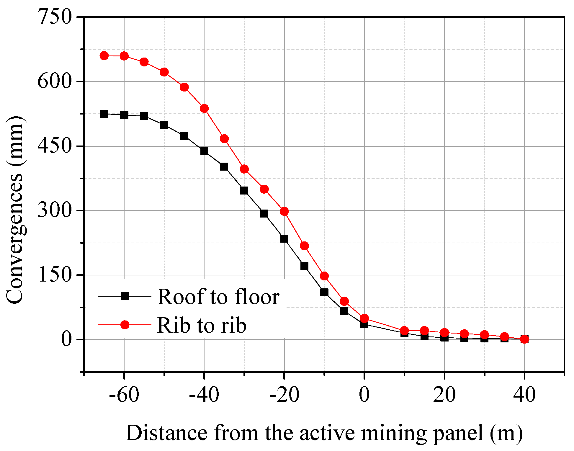
Under the influence of front abutment pressure, when the distance between the displacement monitoring point and the mining face was reduced from 40 m to 0 m, the roof-to-floor and rib-to-rib convergences of the 6212 tail entry increased by 112 mm and 158 mm, respectively, as shown in Figure 4a. Under the influence of side abutment pressure, when the distance between the displacement monitoring point and the mining face changed from 40 m ahead to 60 m behind, the roof-to-floor and rib-to-rib convergences of the 6208 tail entry increased by 1133 mm and 1393 mm, respectively, as shown in Figure 4b. Within the 40 m behind the 6212 working face, the roof-to-floor and rib-to-rib convergences of the 6208 tail entry increased rapidly, and were significantly affected by the 6212 mining panel.
When the 6212 mining panel was not mined, the deformation of the 6208 tail entry was small. However, with the retreating of the 6212 mining panel, the deformation of the small coal pillar along the gob affected by dynamic pressure was severe, resulting in large deformation of the 6208 tail entry and difficulty in roadway maintenance.

3. The Reasons for and Control of a Small Coal Pillar Retaining Roadway Deformation

3.1. Contributing Factors for the 6208 Tail Entry Large Deformation

The width of the coal pillar between the 6208 tail entry and the 6212 tail entry was 5 m. When the 6212 mining panel was retreated, the mine pressure at the gob side of the roadway become violent, and the 6208 tail entry deformed greatly. The main reasons why the 6208 tail entry deformed sharply were as follows. Primarily, the key rock block of the main roof rotated laterally with a large rotation angle. After the 6212 mining panel was retreated, the main roof fracture line appeared on the inside of the coal wall (Figure 5), and the key rock blocks turned laterally. Then the roof load increased, resulting in severe deformation of the 6208 tail entry, which was manifested as roof subsidence, floor heave, and the two sides extruding into the entry, especially the gob side. Subsequently, the compressive strength of the main roof strata was large, and the length of the suspended roof in the gob area was long. The uniaxial compressive strength of rock can be predicted based on a metaheuristic algorithm [28], the function relationship between the P-wave velocity and the point load index [29]. It can also be assessed by laboratory tests, which we used to obtain the uniaxial compressive strength of the rock. Under the uniaxial compression test, the average uniaxial compressive strength of the coal, sandy mudstone and fine sandstone were 9.47 MPa, 29.29 MPa, and 90.05 MPa, respectively, as shown in Figure 6. The compressive strength of the rock on the main roof of the 6212 tail entry reached 90.05 MPa, making it difficult to break the main roof and resulting in a large overhang length of the roof in the gob side area. Moreover, the main roof was thick and the additional load on the small coal pillar was large. The uniaxial compressive strength of the small coal pillar was 9.47 MPa, the bearing strength was low, and the deformation of the small coal pillar along the gob was severe.

3.2. Deformation Control Measures of Small Coal Pillar Retaining Roadway

Considering the large deformation of the small coal pillar roadway, the roadway deformation control measures were proposed based on three aspects: improving the strength of the small coal pillar, resisting the roadway deformation, and changing the roof structure (Figure 7).
(1)
Increasing the strength of small coal pillar. By improving the strength of the small coal pillar, on the one hand, the ability of the small coal pillar to resist deformation can be enhanced; on the other hand, this increase can restrain the rotation of the main roof and reduce the rotation angle. Before the mining panel is retreated, the small coal pillar should be grouted or reinforced with anchor cable in advance to improve the strength of the small coal pillar.
(2)
Resisting the deformation of the gob side roadway. In order to increase the strength of the roadway support and reduce roadway deformation, a single hydraulic prop is used to strengthen the support ahead before retreating the adjacent mining panel.
(3)
Changing the roof structure. The method of directional pre-splitting blasting is used to produce fractures in the roof, so that the main roof fracture line is moved inward to the coal wall side, and the position of the roof fracture line is changed. On the one hand, this can shorten the length of the overhanging beam and reduce the additional load of the main roof; on the other hand, it can make the roof collapse. The filling degree of the gob is thus improved, and the roof support of the gangue in the gob is enhanced. Because of the supporting effect of the gangue in the gob, the rotation and subsidence of the key blocks are reduced, providing a stable stress environment for the roadway along the gob and shortening the period of roof stability.

3.3. Non-Penetrating Directional Pre-Splitting Blasting with a Deep Hole Ahead

3.3.1. Directional Effect of PVC Pipe Punching and Empty Hole in Blasting

LS-DYNA is a general explicit dynamic analysis program, that is especially suitable for solving nonlinear dynamic impact problems with various nonlinear structures, such as high-speed collisions, explosions, and metal form action. LS-DYNA is considered to be the best analysis software for blasting engineering. The LS-DYNA numerical simulation method was used to study the directional effects of PVC pipe punching and empty hole in blasting. The model includes an emulsion explosive, a PVC pipe, air, and rock mass. The blasting hole diameter is 55 mm, the emulsion explosive diameter is 35 mm, the PVC pipe diameter is 50 mm, the wall thickness is 2 mm, and the PVC pipe hole diameter is 4 mm. Lagrange grid modeling was adopted, and the PLANE162 element was used in the modeling. ANSYS finite element software can be used to solve problems such as structures, fluids, electricity, and collisions. The software pre-processing module provides a powerful tool for solid modelling and meshing, which can easily construct a finite element model. Therefore, we used the ANSYS software pre-processing module to build the model and divide the grid. The model boundary is a non-reflection boundary. For the simulated directional pre-splitting blasting effect of the PVC pipe, the model length and width are 1500 mm, with 4511 units and 4632 nodes. For the simulation of the empty hole guiding effect, the model is 4500 mm long and 1500 mm wide, with 12300 units and 12614 nodes. All parts of the model are regarded as isotropy continuous homogeneous media. The emulsion explosive used the MAT_HIGH_EXPLOSIVE_BURN model, with the JWL state equation applied to simulate the relationship between pressure and a specific volume during the explosion. The PVC pipe and rock used the MAT_PLASTIC_KINEMATIC model. The air adopted the NULL constitutive model and used the LINEAR_POLYNOMIAL state equation. The model’s material parameters [30] are shown in Table 1 and Table 2.
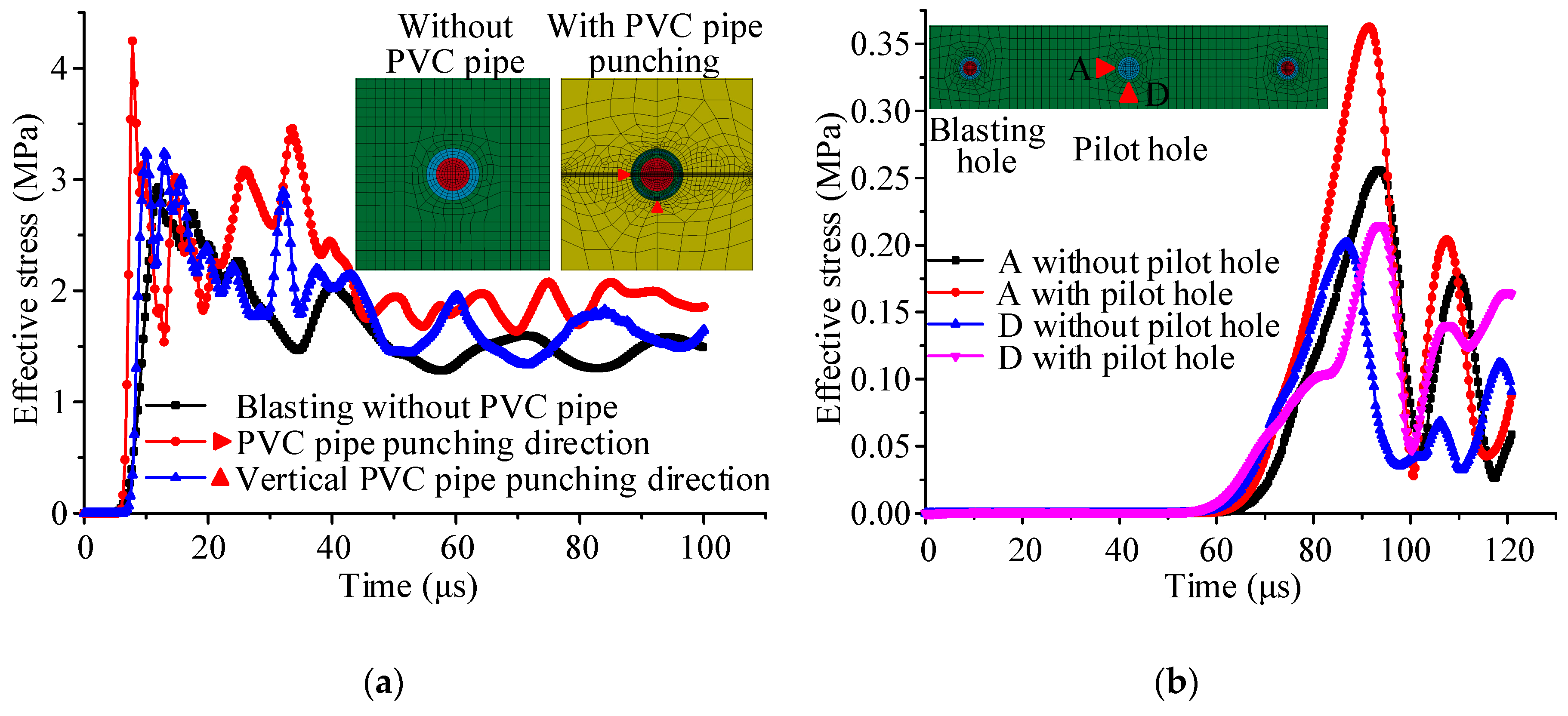
The time–history curve of the hole wall effective stress during blasting is shown in Figure 8. As shown in Figure 8a, when the PVC pipe was not used for blasting, the maximum effective stress of the blasting hole wall was 2.70 MPa. When the PVC pipe was used for blasting, the maximum effective stress of the blasting hole wall in the punching direction was 4.24 MPa, which was 57.03% larger than that of the blasting without the PVC pipe, indicating that the effective stress increased when the PVC pipe was used for blasting. The stress peak value was first reached in the PVC pipe punching direction, and the time to reach the stress peak was 2.20 μs faster than that in the vertical punching direction. The peak stress in the PVC pipe punching direction is the largest, (1.18 MPa greater than that in the vertical punching direction), and the maximum effective stress increased by 36.41%, indicating that the energy accumulation effect of the PVC pipe was obvious. Therefore, the initial fracture was first formed in the PVC pipe punching direction, and the initial fracture fully propagated under the action of the subsequent explosive gas to achieve fracture-oriented propagation. The non-punching direction of the PVC pipe effectively restrained the release and action intensity of the explosive products. The punching direction played a guiding role in the release of the explosive products. The energy then accumulated in the punching direction and strengthened the effect on the rock. Therefore, the directional effect is obvious.
As shown in Figure 8b, when there was no pilot hole, the maximum effective stress of measuring point A and measuring point D was 0.26 MPa, and 0.20 MPa, respectively. When the guide hole was included, the maximum effective stress of measuring point A and measuring point D was 0.38 MPa and 0.22 MPa, respectively, which increased by 46.15% and 10% compared to the lack of a pilot hole. After the charging hole was detonated, the stress wave was aroused in the surrounding rock and propagated outwards. When the stress wave propagated to the pilot hole, the existence of the hole significantly increased the stress value compared to that without the pilot hole, which highlighted the stress concentration effect of the empty hole. Further, the stress concentration effect of the empty hole decreased with an increase in distance. Thus, the pilot hole has a significant effect on the stress distribution. The free surface of the pilot hole increases, concentrates the stress, improves the fracture penetration between the blasting holes, and increases the range of the fracture area.
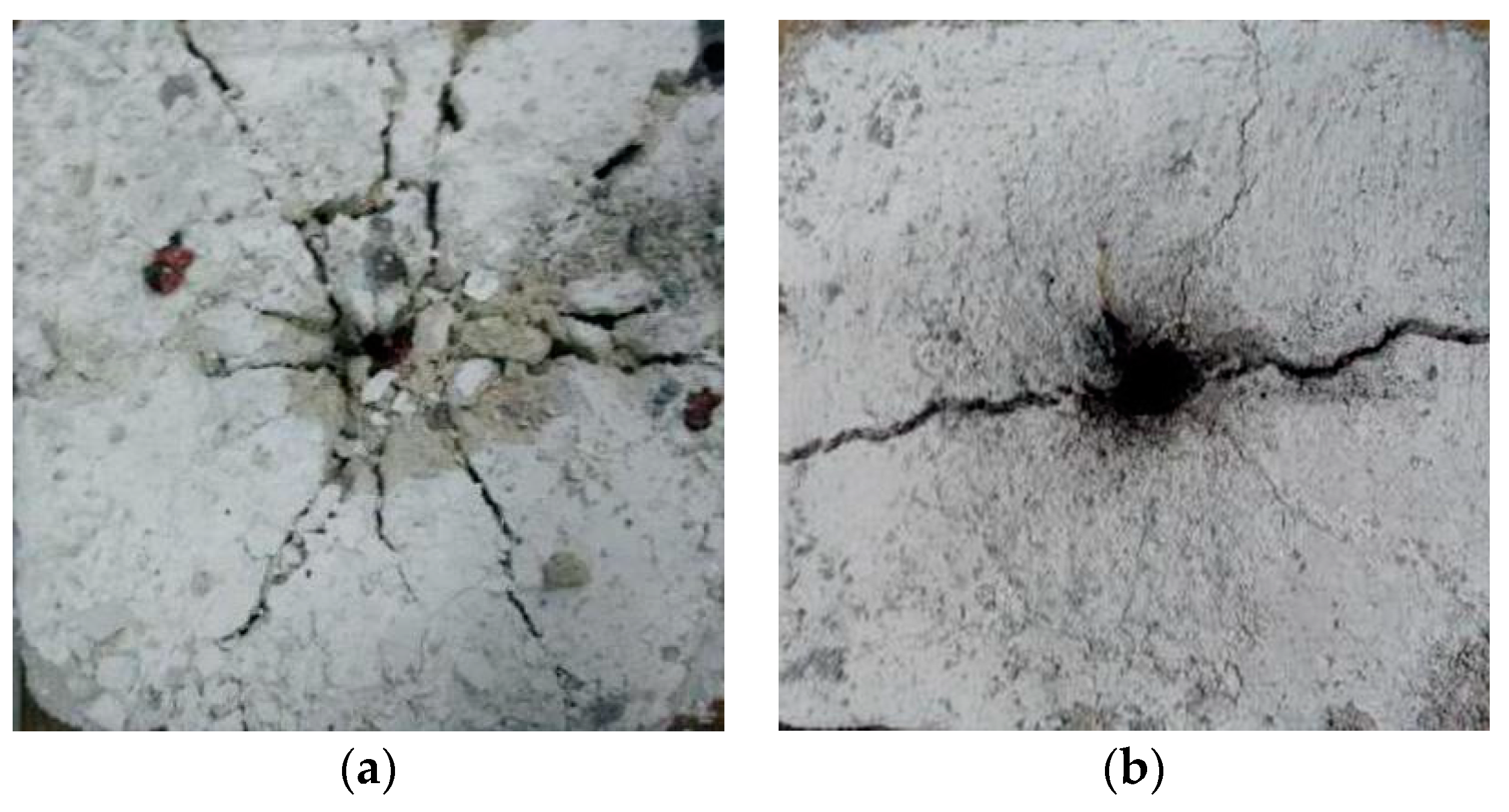
A similar simulation test was used to study the directional blasting effect of the PVC pipe punching. The size of the specimen was 150 mm × 150 mm × 150 mm. The propagation of the blasting fracture is shown in Figure 9. When the PVC pipe was not used (Figure 9a), the blasting fractures were relatively dispersed and the energy was released arbitrarily. The fractures on the surface and side of the model were not fixed, and the model was seriously damaged. When PVC pipe punching was adopted for pre-splitting blasting (Figure 9b), the energy was released along the fixed direction, and straight fractures appeared on the surface and side of the model, showing good model integrity.
To ensure that the roadway roof generated pre-fractures along the axial direction, a PVC pipe was selected as the energy collecting pipe, and holes were punched on both sides of the PVC pipe to achieve two-way cumulative energy. The PVC pipe perforation is shown in Figure 10a. The energy collecting tube was 2000 mm long with 180° punching. The hole diameter was 4 mm and the spacing was 8 mm. The inner radius of the energy collecting tube was 23 mm, the outer radius was 25 mm, and the wall thickness was 2 mm. The charge structure of the PVC energy collecting tube is shown in Figure 10b. Then, the blasting hole was charged via a continuous coupling method with a double detonator and a double detonation cord. During the installation of the PVC pipes, the energy collecting holes were settled along the roadway axially and connected by quick coupling. A schematic diagram of directional pre-splitting blasting fracture propagation is shown in Figure 10c. The rock mass near the blasting hole is broken, and the fracture distribution is scattered; the rock mass far away from the blasting hole produced a single fracture in the punching direction, and the fracture stopped propagating at the empty hole.

3.3.2. Control Principle for Non-Penetrating Fracture Propagation

Fracture directional propagation can be achieved by using PVC pipe punching and empty holes in blasting. The empty holes can block the stress propagation path and prevent the fracture from continuing to propagate. In this way, fracture propagation can be effectively controlled by using PVC pipe punching and a reasonable arrangement of empty holes in blasting.
During the crack propagation process, the stress intensity factor at the tip is
K I = p F π ( r h + l )
where p is the pressure on the wall of the blasting hole, MPa; l is the crack propagation length, m; r h is the radius of the hole, mm; and F is the stress intensity factor correction coefficient,   F is a function of l and r h , F = F [ ( r h + l ) / r h ] , when ( r h + l ) / r h is less than 1.5, F = 2.24 l / ( r h + l ) ; when ( r h + l ) / r h is greater than 1.5, F changes little and tends to 1.
Under the action of quasi-static pressure, the conditions for crack initiation and propagation are as follows:
K I > K I C
where K I C is the rock dynamic fracture toughness, MPa·m1/2.
Thus,
p K I C F π ( r h + l )
The maximum propagation length of the rock crack is [30]
l m a x = r h μ p ( 1 μ ) S d t 1
where S d t is the dynamic uniaxial tensile strength of the rock, MPa.
The maximum crack propagation length can be calculated by substituting the relevant parameters; then, the distance between the blasting hole and the empty hole meets the following requirements:
d l m a x
where d is the distance between the blasting hole and the empty hole, m.
Figure 11 shows a schematic diagram of the borehole arrangement for non-penetrating fracture propagation control. The length of the fracture zone is controlled by changing the number of blasting holes, and the length of the rock mass in non-penetrating areas is controlled by changing the distance between two adjacent crack arresting holes. The pilot hole is arranged in the middle of the two blasting holes, and the crack arresting hole is arranged at the junction of the fracture penetration area and the non-penetration area. On the one hand, the crack arresting holes play a guiding role; on the other hand, they can block the stress wave propagation path, so that the stress wave will not continue to spread forward, thereby preventing the fracture from expanding, and stopping the fracture propagation. The pilot hole and crack arresting hole can be used as observation holes at the same time to track and observe the effects of directional pre-splitting on the roof to realize multi-ple functions of one hole and achieve accurate control and intelligent monitoring of non-penetrating directional fractures. Symmetrical fractures are produced on both sides of the pilot hole, and unilateral fractures are produced on the crack arresting hole.

3.3.3. The Pressure Relief Technology

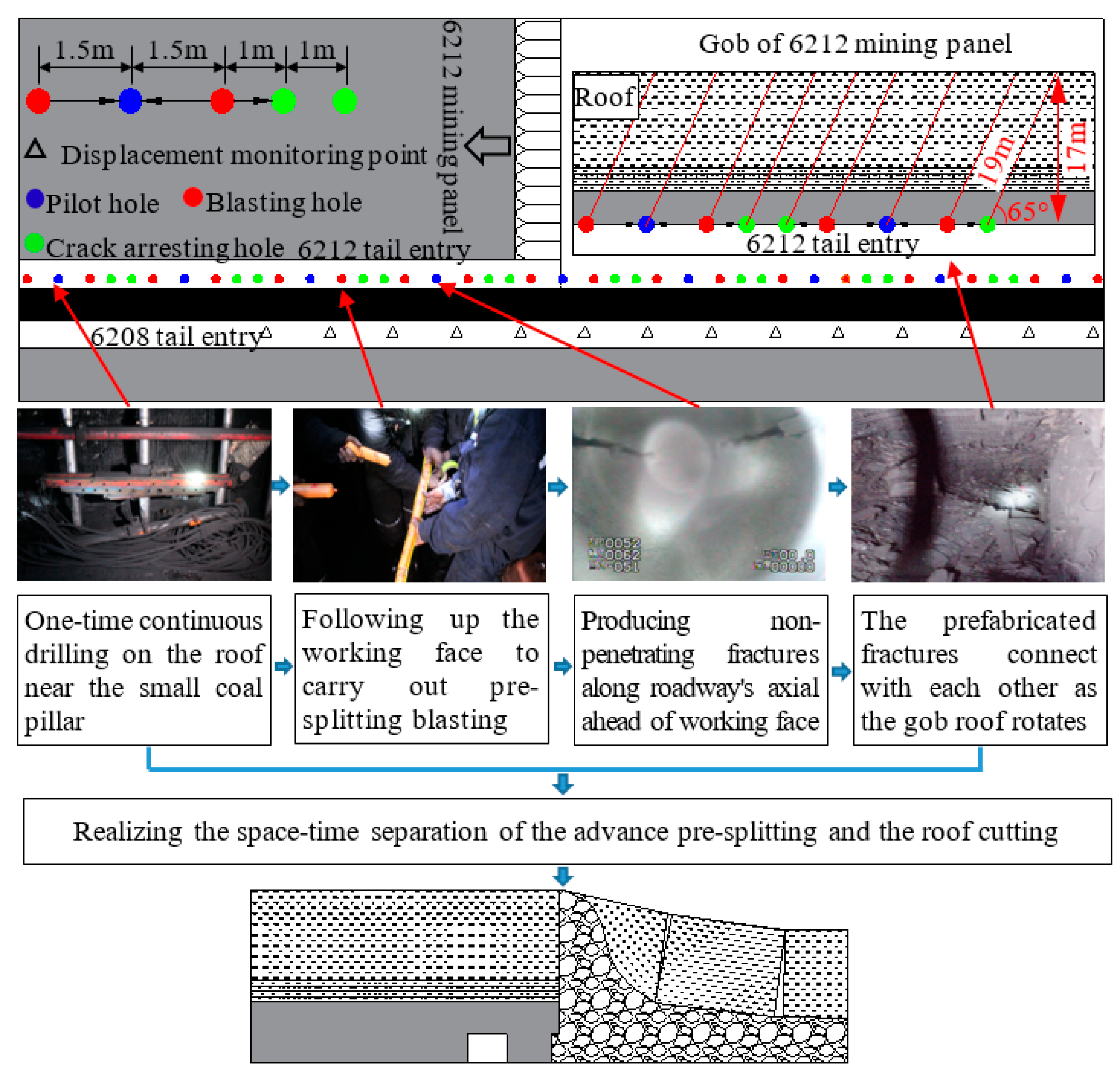
Figure 12 shows the pressure relief technology for non-penetrating directional presplitting blasting with a deep hole ahead. This technology involves continuously drilling holes near the side of the small coal pillar, pre-splitting blasting following mining panel retreating, and pre-fabricating fixed-length non-penetrating fractures along the roadway axial direction. The roof fractures are connected to each other with the rotation of the roof in the gob to complete roof cutting.

4. Numerical Simulation

Fast Lagrangian Analysis of Continua (FLAC3D) is a mechanical analysis software for continuous media, that can simulate and calculate the stress and deformation forms of engineering structures in three-dimensional rock masses, soil, and other media. This software has a strong ability to solve complex mechanical problems, and is widely used in mining engineering. Using the FLAC3D numerical simulation, the influence of the non-penetrating fracture length on the small coal pillar retaining roadway was simulated. The stress and displacement characteristics of the roadway surrounding rock were analyzed after fractures were prefabricated in the roof, and the influence of the interval non-penetrating fractures on the stability of small the coal pillar was studied.

4.1. Global Model and Simulation Scheme

A numerical model was developed using the FLAC3D software based on the geological conditions of the 6212 and 6208 mining panels in Wangzhuang coal mine, as shown in Figure 13. The size of the numerical model was 233 m × 80 m × 100 m, with 396,000 units and 413,457 nodes. The calculation model approximated the coal and rock mass as a homogeneous, continuous, and isotropic medium, while only considering the gravity stress and neglecting the influence of tectonic stress. The Mohr–Coulomb yield criterion was applied in this model. The detailed rock strata properties [1,2,28,29] used in the numerical model are shown in Table 3. This model was surrounded by a sliding boundary, with horizontal constraints imposed, and the horizontal displacement of the boundary was zero. The model’s bottom was a fixed boundary, with vertical constraints imposed, and the vertical displacement of the bottom boundary was zero. The model applied load equivalent to that of the overlying rock layer, i.e., the gravity stress, and the buried depth was 320 m.
Non-penetrating directional pre-splitting blasting with a deep hole produces interval fractures in the roadway roof, and the number of blasting holes between the crack arresting holes determines the length of the pre-splitting fractures. In the simulation, three types of non-penetrating fractures were formed in the roadway roof: two blasting holes formed 5 m interval fractures, three blasting holes formed 8 m interval fractures, and four blasting holes formed 11 m interval fractures. The length of the rock mass in the non-penetrating area was 1 m. At the same time, pre-splitting blasting that produces continuous penetrating fractures and no pre-splitting blasting in the roof were simulated. In this simulation, the width of the roof fracture was 0.01 m, and the height of the fracture was 17 m. The fracture height reached the main roof, and the main roof was cut off. By means of a numerical simulation, the influence of mining panel retreating on roadway stability was studied for a roadway roof without deep hole pre-splitting, a roof with deep-hole pre-splitting producing penetrating fractures, a roof with deep-hole pre-splitting producing non-penetrating fractures.

4.2. Analysis of the Modeling Results

4.2.1. Stress Distribution in the Coal Pillar Center

The stress distribution in the center of the coal pillar with different roof pre-splitting methods, after the pre-splitting blasting in the 6212 tail entry roof when the 6212 mining panel was retreated, is shown in Figure 14.
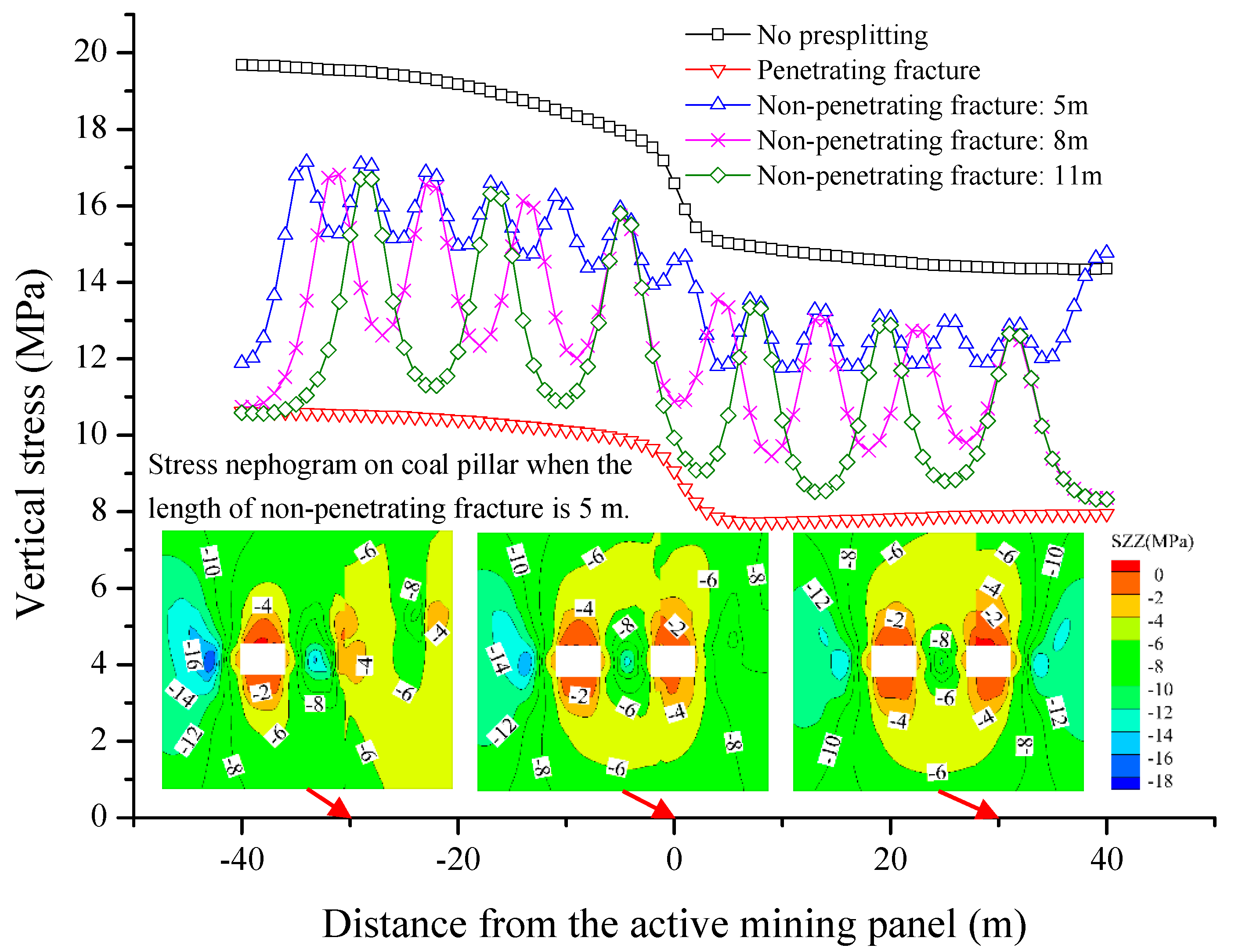
As shown in Figure 14, after excavating the 6212 and 6208 tail entries, the vertical stress in the center of the coal pillar was 14.35 MPa. The overall vertical stress in the coal pillar center decreased because of the redistribution of the surrounding rock stress after the pre-splitting blasting in the 6212 tail entry roof. After the penetrating fractures were produced, the vertical stress in the center of coal pillar was 7.95 MPa, which was reduced by 44.59%. The vertical stress in the center of the coal pillar presented alternately as a wave peak and wave valley after the non-penetrating fracture was produced by presplitting blasting. The stress wave peak was located in the center of the non-penetrating area, and the stress wave valley was at the center of fracture. The vertical stress in the center of the coal pillar in the fracture area was less than that in the rock mass area. When the length of the non-penetrating fractures was 5 m, 8 m, and 11 m, the vertical stresses at the stress wave valley were 11.75 MPa, 9.60 MPa, and 8.52 MPa, respectively, which were reduced by 18.12%, 33.10%, and 40.59%.
When the 6212 mining panel was retreated, the vertical stress in the center of the pillar was 19.68 MPa without pre-splitting blasting in the 6212 tail entry. When pre-splitting blasting was carried out in the 6212 tail entry roof, the vertical stress in the center of the coal pillar decreased significantly after 6212 mining panel retreating, which was beneficial to the maintenance of the 6208 tail entry. The vertical stress in the center of coal pillar was 10.72 MPa after the penetrating fracture was formed by presplitting blasting, which decreased by 45.53%. When the length of the non-penetrating fracture was 5 m, 8 m, and 11 m, the vertical stress at the stress wave valley was 14.74 MPa, 12.61 MPa, and 11.29 MPa, which decreased by 25.10%, 35.92%, and 42.63%, respectively.
Thus, the length of the non-penetrating fracture produced by presplitting blasting affects the vertical stress distribution in the center of coal pillar. The vertical stress in the center of the coal pillar decreases with an increase in the non-penetrating fracture length.

4.2.2. Energy Distribution of the Coal pillar

With the mining panel retreated, the surrounding rock stress of the roadway was redistributed, accompanied by the accumulation and release of energy. The elastic strain energy U e can be expressed as follows:
U e = 1 2 E [ σ 1 2 + σ 2 2 + σ 3 2 2 μ ( σ 1 σ 2 + σ 2 σ 3 + σ 1 σ 3 ) ]
where E is the initial elastic modulus of the rock mass; μ is the Poisson’s ratio of the rock mass; and σ 1 , σ 2 , and σ 3 are the principal stress.
The elastic strain energy inside the unit volume of rock mass is the elastic strain energy density at that point. Therefore, the elastic strain energy density distribution in the coal pillar can be obtained by extracting the principal stress of each numerical calculation point.
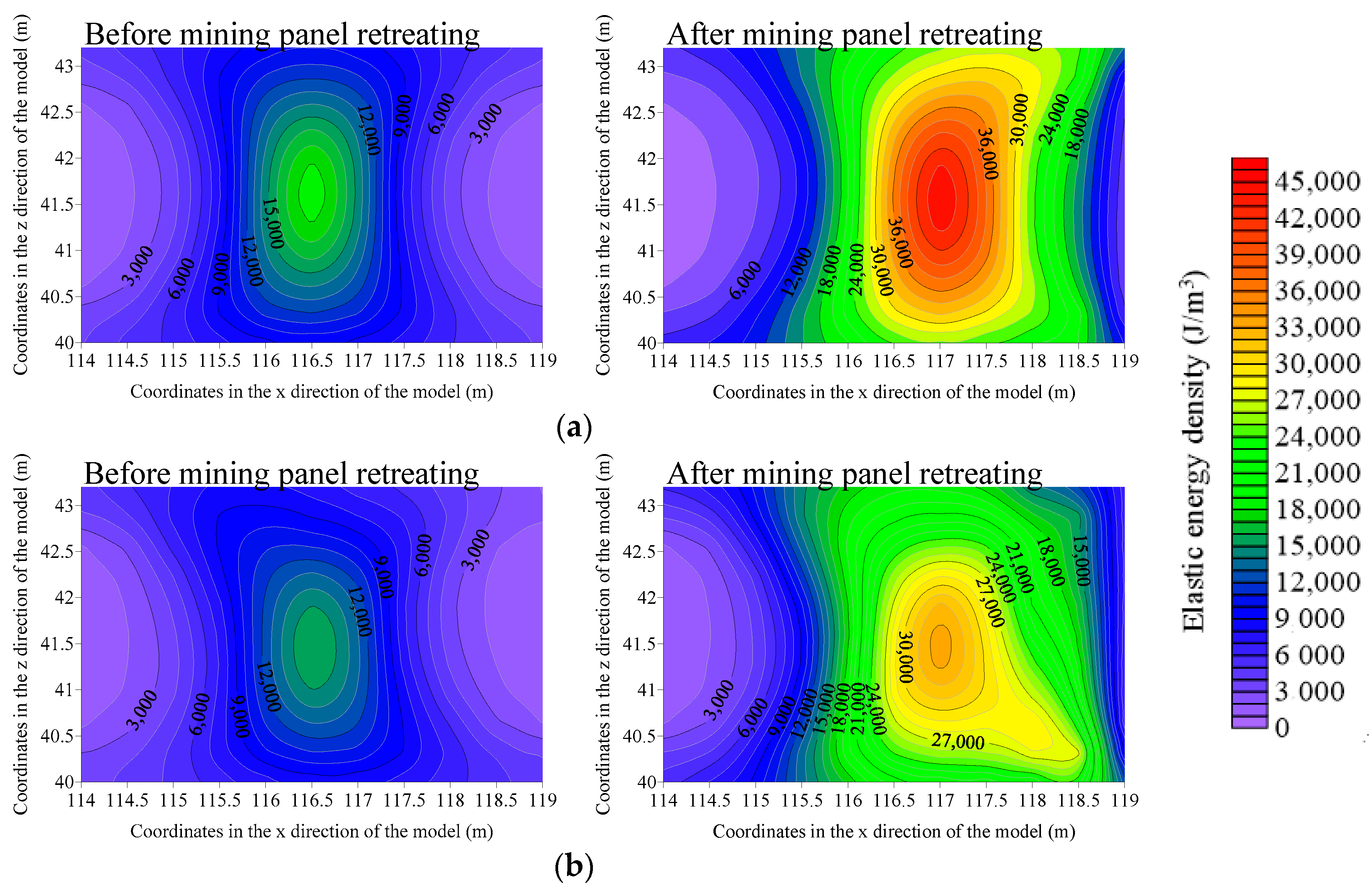
When the roof did not experience presplitting blasting, the maximum released elastic strain energy density of the coal pillar before and after the 6212 mining panel retreating was 18,697 J/m3 and 45,438 J/m3, respectively. The elastic strain energy density in the coal pillar increased by 58.85% after the 6212 mining panel retreated, and the elastic strain energy density of the coal pillar near the gob side was large, as shown in Figure 15a. When the length of the non-penetrating fracture produced by pre-splitting blasting was 5 m, the elastic strain energy density in the coal pillar decreased significantly, as shown in Figure 15b. The maximum elastic strain energy density in the coal pillar before and after the 6212 mining panel retreating was 15,967 J/m3 and 33,459 J/m3, respectively, which was 14.60% and 26.36% lower than that without pre-splitting blasting.
Figure 16 shows the maximum elastic strain energy density that can be released by the coal pillar with different pre-splitting blasting methods. The maximum released elastic strain energy density in the coal pillar can be significantly reduced by the method of non-penetrating pre-splitting blasting, where the energy accumulation is related to the length of the non-penetrating fracture. The elastic strain energy density decreased with an increase in the length of the non-penetrating fracture. After the non-penetrating fracture was produced, the energy accumulation path was cut off. When the 6212 mining panel was retreated, the energy released to the adjacent roadway decreased, thereby achieving the purpose of roadway protection.

4.2.3. Vertical Stress Distribution at the Working Face End

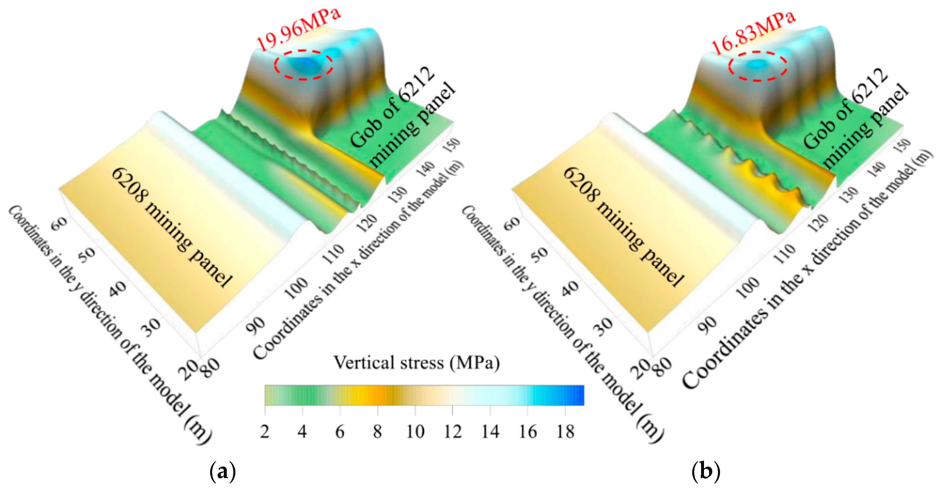
The roof stress distribution characteristics under 6212 mining panel retreating is shown in Figure 17. The maximum stress distribution at the end of the working face with different roof pre-splitting blasting methods is shown in Figure 18. The maximum vertical stress at the end of the 6212 working face was 16.63 MPa without pre-splitting blasting, and the maximum vertical stress at the end of the 6212 working face was 19.96 MPa with presplitting blasting producing a penetrating fracture, which was 20.02% higher than that without presplitting blasting. When the length of the non-penetrating fracture was 5 m, 8 m, and 11 m, the maximum vertical stress at the end of the 6212 working face was 16.83 MPa, 17.81 MPa, and 18.92 MPa, respectively. With an increase in the non-penetrating fracture length, the maximum vertical stress at the end of the working face increased gradually.
The maintenance of the working face end is affected by the length of the non-penetrating fracture, and the vertical stress of the working face end increases with an increase in the length of the non-penetrating fracture. In particular, when a penetrating fracture is produced, the fully-mechanized hydraulic support is crushed and becomes difficult to move at the end of the working face, which problematizes the safe and efficient retreating of the working face. Therefore, in order to ensure the maintenance of the working face end, it is necessary to reasonably select the number of blasting holes between the crack arresting holes and determine the length of the non-penetrating fracture.

4.2.4. Deformation of the 6212 Tail Entry and 6208 Tail Entry

The deformation of the 6212 tail entry after the 6212 mining panel was retreated following up pre-splitting blasting is shown in Figure 19. No pre-splitting blasting was carried out in the 6212 tail entry roof. When the 6212 mining panel was retreated, the deformation of the 6212 tail entry increased with a decrease in the distance from the active mining panel. The roof-to-floor and rib-to-rib maximum convergences of the 6212 tail entry were 194 mm and 281 mm, respectively. When the penetrating fracture was produced by pre-splitting blasting, the roof-to-floor and rib-to-rib maximum convergences of the 6212 tail entry were 292 mm and 416 mm, respectively, which was 50.51% and 48.04% higher than that without presplitting blasting. The length of the non- penetrating fracture was 5 m, 8 m, and 11 m, when the 6212 mining panel was retreated, the maximum deformation of the roof-to-floor of the 6212 tail entry was 240 mm, 249 mm, and 259 mm, respectively, which increased by 23.71%, 28.35%, and 33.51% compared to that with no pre-splitting blasting. The maximum deformation of the rib-to-rib was 326 mm, 342 mm, and 361 mm, respectively, which increased by 16.01%, 21.71%, and 28.47% compared to that with no pre-splitting blasting. With an increase in the length of the non-penetrating fracture, the deformation of the 6212 tail entry increased. When pre-splitting blasting was carried out on the roof of the 6212 tail entry, the advanced deformation of the roadway increased after the mining panel was retreated, especially when the non-penetrating fracture was produced. Therefore, a non-penetrating fracture can effectively control roadway deformation when the mining panel is retreated. To reduce the influence of pre-splitting blasting on roadway deformation, it is necessary to determine the reasonable length of the non-penetrating fracture and choose a reasonable number of blasting holes.
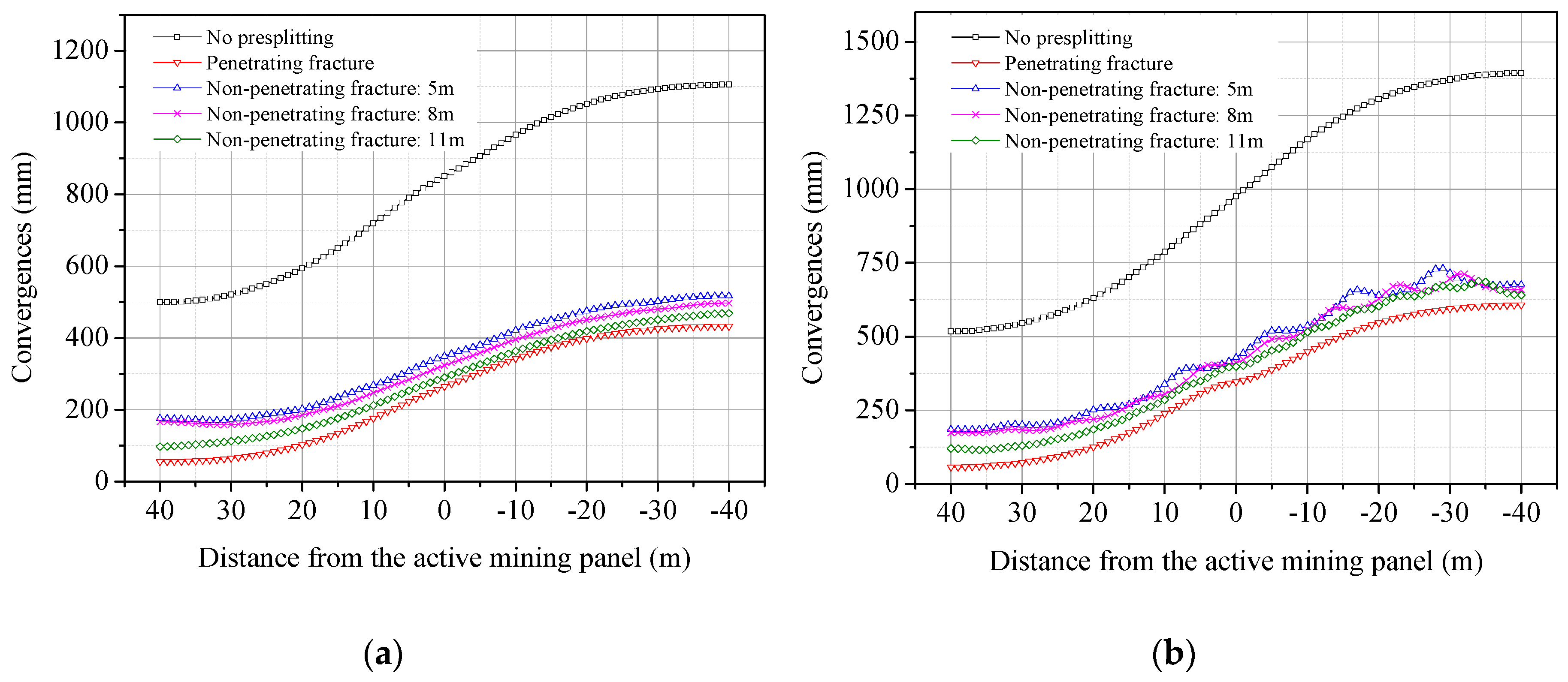
The deformation of the 6208 tail entry when the 6212 mining panel was retreated after the pre-splitting blasting is shown in Figure 20. By the retreating the 6212 working face, the deformation of the 6208 tail entry gradually increased due to the influence of mining. No pre-splitting blasting was carried out in the roof of the 6212 tail entry; the roof-to-floor and rib-to-rib maximum convergences of the 6208 tail entry were 1105 mm and 1394 mm, respectively. When the penetrating fracture was produced by pre-splitting blasting, the roof-to-floor and rib-to-rib maximum convergences of the 6208 tail entry were 432 mm and 607 mm, respectively, which was 60.90% and 56.46% lower than that without presplitting blasting. The length of the non-penetrating fracture was 5 m, 8 m, and 11 m, when the 6212 mining panel was retreated, and the maximum deformation of the roof-to-floor of the 6208 tail entry was 517 mm, 497 mm, and 468 mm respectively, which decreased by 53.21%, 55.02%, and 57.65% compared to that with no pre-splitting blasting. The maximum deformation of the rib-to-rib of the 6208 tail entry was 676 mm, 659 mm, and 641 mm respectively, which decreased by 51.51%, 52.73% and 54.02% compared to that with no pre-splitting blasting. The deformation of the adjacent 6208 tail entry decreased as a whole, and the deformation of the roadway was significantly reduced by presplitting blasting. After retreating the 6212 mining panel, on the one hand, the gob roof collapsed sufficiently and completely filled the gob to support the overlying strata; on the other hand, the main roof was cut off and the roof load was reduced, thereby reducing the deformation of the roadway. Therefore, pre-splitting blasting can effectively reduce the deformation of the adjacent roadway to achieve the purpose of roadway protection. Roadway deformation is related to the length of the non-penetrating fracture, and roadway deformation decreases with an increase in the length of the non-penetrating fracture.

5. Field Application

According to the engineering geological conditions of the 6212 mining panel and the 6208 mining panel in Wangzhuang Coal Mine, the pressure relief technology of non-penetrating directional presplitting blasting with a deep hole ahead (Figure 11) was achieved. To effectively reduce the deformation and energy accumulation of the small coal pillar roadway and ensure the maintenance of the pre-splitting blasting roadway and working face end, two blasting holes were used between the crack arresting holes in the field application. The parameters of the deep hole non-penetrating directional pre-splitting blasting are shown in Table 4. The application of the deep hole non-penetrating directional pre-splitting blasting technology in the 6212 tail entry roof not only cut off the connection between the 6208 tail entry roof and the 6212 mining panel roof but also optimized the stress environment of the coal pillar and the surrounding rock of the 6208 tail entry.
The effect of non-penetrating directional pre-splitting blasting was observed by using a drilling peep instrument, and the fracture propagation characteristics in the blasting holes, the pilot holes and the crack arresting holes were obtained, as shown in Figure 10. The rock mass in the blasting hole was broken, the fracture distribution was scattered, and the fracture extended to the empty holes on both sides of the blasting hole. Two main fractures were produced along the pre-splitting direction in the pilot hole, indicating that the fractures here achieved penetration. There was only one side fracture in the crack arresting hole, and the rock mass between the adjacent crack arresting hole was complete, producing a non-penetrating zone. The observation results showed that the roof of the small coal pillar roadway achieved the effect of non-penetrating directional pre-splitting with a deep hole.
After non-penetrating directional pre-splitting blasting with a deep hole, when the 6212 mining panel was retreated, the roof-to-floor and rib-to-rib maximum convergences of the 6208 tail entry were 525 mm and 660 mm, respectively, as shown in Figure 21. Compared to the results without directional presplitting blasting (Figure 4b), the roof-to-floor and rib-to-rib maximum convergences of the 6208 tail entry were reduced by 608 mm and 733 mm, respectively, presenting a decrease of 53.66% and 52.62%. This result demonstrates that the field application effect is significant.

6. Discussion

For the gob-side entry retaining by roof presplitting, He et al. [23], Gao et al. [26], and Wang et al. [27] used the directional presplitting blasting method to produce a continuous penetrating fracture in the roadway roof, so that the roof collapsed, and the gangue filled the roadway gob to construct the supporting body beside the roadway. According to the characteristics of the small coal pillar retaining roadway, we applied the pressure relief technology for non-penetrating directional presplitting blasting with a deep hole ahead. Using directional pre-splitting blasting, interval non-penetrating fractures were generated, and the roof structure was changed to protect the small coal pillar roadway. The main advantages of non-penetrating directional presplitting blasting with a deep hole ahead are the following. First, the use of deep-hole blasting can ensure the effect of roof pre-splitting and avoid affecting the existing support system of the roadway. Second, by using prefabricated non-penetrating fractures in front of the working face instead of penetrating fractures, the roadway roof maintains continuity and self-stability, which are conducive to maintaining the stability of the working face end surrounding rock. In the rear of the working face, the non-penetrating fractures prefabricated in the roof are connected with each other under rotary action, and the roof cutting is completed, thereby realizing the space–time separation of pre-splitting and roof cutting. Third, blasting at a reasonable distance ahead of the working face can ensure the stability of the surrounding rock at the working face end while avoiding a blasting hole collapse, thus providing conditions for one-time continuous drilling, simplifying the construction process, and improving construction efficiency.
Our research found that the non-penetrating fracture length affects the results of non-penetrating directional pre-splitting blasting. The deformation of the roadway in the adjacent working face decreases with an increase in the non-penetrating fracture length. However, the working face end area’s vertical stress increases with this increase in non-penetrating fracture length. Therefore, to ensure maintenance of the working face end, it is necessary to reasonably select the number of blasting holes between the crack arresting holes and determine the length of non-penetrating fracture. Two blasting holes were used between the crack arresting holes for the field application. The field application results showed that the deformation of the adjacent small pillar roadway decreased significantly. The numerical simulation results are basically the same as the field application results, which verifies the correctness of the numerical simulation results. The roadway section meets the demands of mining panel high-efficiency retreating, thus demonstrating the rationality of the technical and numerical simulation results.
By using a similar method of simulation in the laboratory, we verified that the use of PVC pipe perforation in blasting can cause the crack to propagate directionally. The influence of the roadway strata’s heterogeneity [31] on the PVC pipe’s directional effect was not considered. Therefore, the influence of the roadway strata’s heterogeneity on the PVC pipe’s directional effect is one of our future research directions. In addition, because non-penetrating fracture length is the most critical parameter, we used a FLAC3D numerical simulation to analyze the influence of the non-penetrating fracture length on the directional pre-splitting effect. The influence degree and sensitivity degree [32] of parameters such as rock mass length, pre-fracture depth, and pre-fracture angle on the effect of non-penetrating directional pre-splitting is another one of our future research directions.

7. Conclusions

The principle of non-penetrating fracture directional control was studied, and a pressure relief technology for non-penetrating directional presplitting blasting with a deep hole ahead was proposed. The influence of non-penetrating fracture length on the pre-splitting effect was studied by numerical simulation, and a field application was carried out. The conclusions drawn from this study are summarized as follows.
(1)
The lateral rotation of the key rock blocks of the main roof after retreating in the adjacent mining panel and the high compressive strength of the main roof strata caused large deformation of the small coal pillar roadway. Roadway deformation control measures were thus proposed with three goals: improving the strength of the small coal pillar, resisting roadway deformation, and changing the roof’s structure.
(2)
Fracture propagation can be effectively controlled by reasonably setting the position of the empty hole for non-penetrating directional pre-splitting blasting. The length of the fracture zone is controlled by changing the number of blasting holes, and the length of the rock mass in the non-penetrating area is controlled by changing the distance between the two adjacent crack arresting holes.
(3)
The vertical stress in the center of the coal pillar, the energy accumulation in the coal pillar, the stress at the end of the working face, and roadway deformation are related to the length of the non-penetrating fracture produced by pre-splitting blasting. The number of blasting holes must be selected reasonably to determine the length of the non-penetrating fractures.
(4)
The field application results showed that the roof-to-floor and rib-to-rib maximum convergences of the 6208 tail entry were reduced by 608 mm and 733 mm, respectively.
In summary, the pressure relief technology for non-penetrating directional presplitting blasting with a deep hole ahead was used to protect a small coal pillar roadway. This technology is an important breakthrough in the technical field of small coal pillar roadway protection, and can also be used to reduce the width of coal pillars and improve the recovery rate of coal resources.

Author Contributions

Conceptualization, S.C., Z.M. and P.G.; methodology, S.C., Z.M. and P.G.; software, S.C. and N.L.; validation, S.C., Z.M. and T.W.; formal analysis, S.C.; investigation, S.C. and K.L.; resources, S.C. and Z.M.; data curation, S.C. and K.L.; writing—original draft preparation, S.C.; writing—review and editing, S.C., Z.M. and P.G.; visualization, S.C.; supervision, Z.M.; project administration, Z.M.; funding acquisition, Z.M. and P.G. All authors have read and agreed to the published version of the manuscript.

Funding

This research was funded by the National Natural Science Foundation of China, grant number 51674250, 51804302, China Postdoctoral Science Foundation, grant number 2019M652018, Major Program of National Natural Science Foundation of China, grant number 51734009, 51323004, and National Key Research and Development Projects of China, grant number 2019YFC1904304.

Conflicts of Interest

The authors declare no conflict of interest.

References

  1. Feng, G.; Wang, P.; Chugh, Y.P.; Zhao, J.; Wang, Z.; Zhang, Z. A coal burst mitigation strategy for tailgate during deep mining of inclined longwall top coal caving panels at huafeng coal mine. Shock Vib. 2018, 2018, 1–18. [Google Scholar] [CrossRef]
  2. Feng, G.; Wang, P.; Chugh, P.Y. A new gob-side entry layout for longwall top coal caving. Energies 2018, 11, 1292. [Google Scholar] [CrossRef] [Green Version]
  3. Wang, Q.; Gao, H.; Jiang, B.; Li, S.; He, M.; Wang, D.; Lu, W.; Qin, Q.; Gao, S.; Yu, H. Research on reasonable coal pillar width of roadway driven along goaf in deep mine. Arab. J. Geosci. 2017, 10, 1–17. [Google Scholar] [CrossRef]
  4. Qian, G.; Shi, W.; Xu, L. Ground Pressure and Strata Control, 2nd ed.; China University of Mining and Technology Press: Xuzhou, China, 2010; pp. 221–230. [Google Scholar]
  5. Wu, W.; Bai, J.; Wang, X.; Yan, S.; Wu, S. Numerical study of failure mechanisms and control techniques for a gob-side yield pillar in the Sijiazhuang coal mine, China. Rock Mech. Rock Eng. 2019, 52, 1231–1245. [Google Scholar] [CrossRef]
  6. Li, W.; Bai, J.; Peng, S.; Wang, X.; Xu, Y. Numerical modeling for yield pillar design: A case study. Rock Mech. Rock Eng. 2015, 48, 305–318. [Google Scholar] [CrossRef]
  7. Huang, B.; Liu, J.; Zhang, Q. The reasonable breaking location of overhanging hard roof for directional hydraulic fracturing to control strong strata behaviors of gob-side entry. Int. J. Rock Mech. Min. 2018, 103, 1–11. [Google Scholar] [CrossRef]
  8. Huang, B.; Chen, S.; Zhao, X. Hydraulic fracturing stress transfer methods to control the strong strata behaviours in gob-side gateroads of longwall mines. Arab. J. Geosci. 2017, 10, 1–13. [Google Scholar] [CrossRef]
  9. Bai, Q.; Tu, S.; Wang, F.; Zhang, C. Field and numerical investigations of gateroad system failure induced by hard roofs in a longwall top coal caving face. Int. J. Coal. Geol. 2017, 173, 176–199. [Google Scholar] [CrossRef]
  10. Peng, S.S. Longwall Mining, 3rd ed.; CRC Press: London, UK, 2020; pp. 87–102. [Google Scholar]
  11. Liu, S.; Wan, Z.; Zhang, Y.; Lu, S.; Ta, X.; Wu, Z. Research on evaluation and control technology of coal pillar stability based on the fracture digitization method. Measurement 2020, 158, 1–8. [Google Scholar] [CrossRef]
  12. Li, X.; Zhang, N.; Xie, Z.; Liang, D.; Zhao, Y. Study on efficient utilization technology of coal pillar based on gob-side entry driving in a coal mine with great depth and high production. Sustainability 2019, 11, 1706. [Google Scholar] [CrossRef] [Green Version]
  13. Zhang, H.; Wan, Z.; Ma, Z.; Zhang, Y. Stability control of narrow coal pillars in gob-side entry driving for the LTCC with unstable overlying strata: A case study. Arab. J. Geosci. 2018, 11, 665. [Google Scholar] [CrossRef]
  14. Wattimena, R.K.; Kramadibrata, S.; Sidi, I.D.; Azizi, M.A. Developing coal pillar stability chart using logistic regression. Int. J. Rock Mech. Min. 2013, 58, 55–60. [Google Scholar] [CrossRef]
  15. Qin, S.; Jiao, J.J.; Tang, C.A.; Li, Z. Instability leading to coal bumps and nonlinear evolutionary mechanisms for a coal-pillar-and-roof system. Int. J. Solids Struct. 2006, 43, 7407–7423. [Google Scholar] [CrossRef] [Green Version]
  16. Shahri, A.A.; Asheghi, R. Optimized developed artificial neural network-based models to predict the blast-induced ground vibration. Innov. Infrastruct. Solut. 2018, 3, 1–10. [Google Scholar]
  17. Xu, X.; He, M.; Zhu, C.; Lin, Y.; Cao, C. A new calculation model of blasting damage degree—Based on fractal and tie rod damage theory. Eng. Fract. Mech. 2019, 220, 1–12. [Google Scholar] [CrossRef]
  18. Wang, Y. Study of the dynamic fracture effect using slotted cartridge decoupling charge blasting. Int. J. Rock Mech. Min. 2017, 96, 34–46. [Google Scholar] [CrossRef]
  19. Yue, Z.W.; Yang, L.Y.; Wang, Y.B. Experimental study of crack propagation in polymethyl methacrylate material with double holes under the directional controlled blasting. Fatigue Fract. Eng. M 2013, 36, 827–833. [Google Scholar] [CrossRef]
  20. Ma, G.W.; An, X.M. Numerical simulation of blasting-induced rock fractures. Int. J. Rock Mech. Min. 2008, 45, 966–975. [Google Scholar] [CrossRef]
  21. Jayasinghe, L.B.; Shang, J.; Zhao, Z.; Goh, A.T.C. Numerical investigation into the blasting-induced damage characteristics of rocks considering the role of in-situ stresses and discontinuity persistence. Comput. Geotech. 2019, 116, 103207. [Google Scholar] [CrossRef]
  22. Yang, R.; Ding, C.; Li, Y.; Yang, L.; Zhao, Y. Crack propagation behavior in slit charge blasting under high static stress conditions. Int. J. Rock Mech. Min. 2019, 119, 117–123. [Google Scholar] [CrossRef]
  23. He, M.; Gao, Y.; Yang, J.; Gong, W. An innovative approach for gob-side entry retaining in thick coal seam longwall mining. Energies 2017, 10, 1785. [Google Scholar] [CrossRef] [Green Version]
  24. Wang, Y.; Gao, Y.; Wang, E.; He, M.; Yang, J. Roof deformation characteristics and preventive techniques using a novel non-pillar mining method of gob-side entry retaining by roof cutting. Energies 2018, 11, 627. [Google Scholar] [CrossRef]
  25. Sun, X.; Gan, L.; Chengwei, Z.; Jianquan, T.; Manchao, H.; Peng, S.; Chengyu, M. Numerical investigation of gob-side entry retaining through precut overhanging hard roof to control rockburst. Adv. Civ. Eng. 2018, 2018, 1–10. [Google Scholar] [CrossRef] [Green Version]
  26. Gao, Y.; Wang, Y.; Yang, J.; Zhang, X.; He, M. Meso-and macroeffects of roof split blasting on the stability of gateroad surroundings in an innovative non-pillar mining method. Tunn. Undergr. Sp. Tech. 2019, 90, 99–118. [Google Scholar] [CrossRef]
  27. Wang, Q.; He, M.; Yang, J.; Gao, H.; Jiang, B.; Yu, H. Study of a no-pillar mining technique with automatically formed gob-side entry retaining for longwall mining in coal mines. Int. J. Rock Mech. Min. 2018, 110, 1–8. [Google Scholar] [CrossRef]
  28. Asheghi, R.; Shahri, A.A.; Khorsand, Z.M. Prediction of uniaxial compressive strength of different quarried rocks using metaheuristic algorithm. Arab. J. Sci. Eng. 2019, 44, 8645–8659. [Google Scholar] [CrossRef]
  29. Shahri, A.A.; Larsson, S.; Johansson, F. Updated relations for the uniaxial compressive strength of marlstones based on P-wave velocity and point load index test. Innov. Infrastruct. Solut. 2016, 1, 1–7. [Google Scholar]
  30. Yang, S.; Yang, L.; Gao, T. Theory and Practice of Directional Fracture Controlled Blasting, 1st ed.; Science Press: Beijing, China, 2017; pp. 19–25. [Google Scholar]
  31. Ghaderi, A.; Shahri, A.A.; Larsson, S. An artificial neural network based model to predict spatial soil type distribution using piezocone penetration test data (CPTu). B Eng. Geol. Environ. 2019, 78, 4579–4588. [Google Scholar] [CrossRef] [Green Version]
  32. Asheghi, R.; Hosseini, S.A.; Saneie, M.; Shahri, A.A. Updating the neural network sediment load models using different sensitivity analysis methods: A regional application. J. Hydroinform. 2020, 22, 562–577. [Google Scholar] [CrossRef] [Green Version]
Figure 1. Schematic diagram of the coal pillar retaining roadways.
Energies 13 03084 g001
Figure 2. Mine location and panel layout of the study site: (a) mine location; (b) panel layout of the study site.
Energies 13 03084 g002
Figure 3. Stratigraphic column and geological description.
Energies 13 03084 g003
Figure 4. Roadway deformation characteristics during the 6212 mining panel retreating: (a) 6212 tail entry; (b) 6208 tail entry.
Energies 13 03084 g004
Figure 5. Schematic diagram of the key block lateral rotation of the main roof.
Energies 13 03084 g005
Figure 6. Stress–strain curve and failure morphology of the specimen under uniaxial compression.
Energies 13 03084 g006
Figure 7. Roadway deformation control strategy for the small coal pillar retaining roadway.
Energies 13 03084 g007
Figure 8. Time–history curve of the blasting hole wall effective stress: (a) directional pre-splitting blasting with PVC pipe punching; (b) effect of an empty hole on blasting.
Energies 13 03084 g008
Figure 9. Blasting fracture propagation: (a) blasting without a PVC pipe; (b) directional blasting with PVC pipe punching.
Energies 13 03084 g009
Figure 10. PVC pipe charging structure and directional fracture propagation: (a) PVC pipe size and perforation; (b) PVC pipe charging structure; (c) directional blasting fracture propagation.
Energies 13 03084 g010aEnergies 13 03084 g010b
Figure 11. Borehole arrangement for non-penetrating fracture propagation control.
Energies 13 03084 g011
Figure 12. Pressure relief technology for non-penetrating directional presplitting blasting with a deep hole ahead.
Energies 13 03084 g012
Figure 13. Configuration of the 3D model used in the numerical simulation.
Energies 13 03084 g013
Figure 14. Stress distribution characteristics of the coal pillar center.
Energies 13 03084 g014
Figure 15. Effect of pre-splitting blasting on the elastic strain energy density of the coal pillar: (a) no pre-splitting; (b) length of the non-penetrating fracture: 5 m.
Energies 13 03084 g015
Figure 16. Maximum released elastic strain energy density of the coal pillar.
Energies 13 03084 g016
Figure 17. The roof stress distribution characteristics under 6212 mining panel retreating: (a) penetrating fracture; (b) length of the non-penetrating fracture: 5 m.
Energies 13 03084 g017
Figure 18. Stress distribution at the working face end with different roof cutting methods.
Energies 13 03084 g018
Figure 19. Deformation characteristics of the 6212 tail entry: (a) roof-to-floor convergence; (b) rib-to-rib convergence.
Energies 13 03084 g019
Figure 20. Deformation characteristics of the 6208 tail entry: (a) roof-to-floor convergence; (b) rib-to-rib convergence.
Energies 13 03084 g020
Figure 21. Deformation characteristics of the 6208 tail entry.
Energies 13 03084 g021
Table 1. Emulsion explosive parameters.
MaterialDensity (kg/m3)Detonation Velocity (m/s)Chapman–Jouget Pressure (GPa)Initial Internal Energy (MJ/m3)
emulsion explosive12505000146540
Table 2. Model’s material parameters.
MaterialDensity (kg/m3)Young’s Modulus (GPa)Poisson’s RatioYield Strength (MPa)
PVC Pipe13003.60.381.2
Rock2595550.2790.05
Air1.252
Table 3. Rock strata properties used in the numerical model.
Rock StrataBulk Modulus (GPa)Shear Modulus (GPa)Cohesion (MPa)Friction Angle (°)Density (kg/m3)Tensile Strength (MPa)
Overlying Strata 62.361.531.893324200.89
Overlying Strata 52.781.281.563322500.59
Overlying Strata 42.361.531.893324200.89
Overlying Strata 32.781.281.563322500.59
Overlying Strata 28.621.664.643525951.43
Overlying Strata 12.081.251.503223600.53
Main Roof8.621.664.643525951.43
Immediate Roof2.361.531.893324200.89
Coal Seam2.371.181.562814000.58
Immediate Floor2.781.281.563322500.59
Main Floor7.621.513.453626951.16
Underlying Strata 52.781.281.563322500.59
Underlying Strata 42.361.531.893324200.89
Underlying Strata 37.621.513.453626951.16
Underlying Strata 22.781.281.563322500.59
Underlying Strata 12.361.531.893324200.89
Table 4. Non-penetrating directional pre-splitting blasting parameters.
Vertical Drilling Deep (m)17Drilling Dip Angle (°)65
Drilling Length(m)19Drilling Diameter(mm)55
Emulsion Explosive Diameter(mm)35Fracture Arrest Hole Spacing(m)1
Distance Between Fracture Stop Hole and Blasting Hole(m)1Distance Between Pilot Hole and Blasting Hole(m)1.5
Blasting Hole Spacing(m)3Charge Length(m)10
Charge Weight(kg)10Total Length of PVC Pipe(m)10