1. Introduction
When electric machines were used in speed closed-loop in factories, direct-current (DC) motors were the first ones to be implemented, because they have a decoupled electromagnetic torque relationship. This decupled relationship allows for us to handle the main magnetic flux (stator) and the rotor’s current, so controlling the speed of the motor by the armatures’ current is attractive. This relationship allows for keeping the stator magnetic flux constant, and the speed control only deals with the rotor’s current for controlling the motor’s speed. Thus, this kind of electric drive is very used in academia and industry, and a modification of this DC drive is done when brushless motors were designed. However, these DC motors are based on brushed DC motors. A general classification of DC motors is based on brushed and brushless motors. Those brushed and brushless DC motors are widely used in manufacturing CNC machines such as the reconfigurable micro-CNC-machine that allows to validate advanced control systems shown in [
1,
2] that includes DC drives. This type of micro- CNC machines help academia and industries to validate complex control algorithms under several reconfigurations of the micro-CNC machine so engineering students and designers can test and validate advanced control systems in real time applications. Moreover, this platform allows to deploy advanced proposed controllers into complex manufacturing applications so innovation in education is promoted in universities when they design this type of micro-CNC machines integrating advanced controllers such as the proposed controller in this paper since engineering students are able to learn how to move from co-simulation to implementation is a friendly manner. As a result, this paper also provides an entire design methodology for designing advanced electric robust controllers for DC drives using software and digital systems that are familiar to universities and industries so this proposed design methodology can be followed by engineering students or industrial designers.
These DC motors could be controlled while using a power electronic stage that receives the command signal from the speed controller. The power electronic stage generates a Pulse Width Modulation (PWM) voltage signal that is transmitted to the motor’s voltage terminals to achieve the reference speed. Usually, the speed controllers are designed by a Proportional-Integral-Derivative (PID) controller that can reach an excellent speed performance. Nevertheless, this PID controller has critical problems when the motor’s parameters are changing, or load torque is not bounded. As a result, the current motor speed is affected. It is important to propose a new controller, which improves the motor speed performance when mechanical load disturbances appeared, and the motor parameters changed. The close loop of the DC drive can be described using the controller, the power electronics, and the DC motor as the main blocks. For this purpose, it used a MyRIO module, a DC motor, a speed sensor, and power electronics as a single unit for teaching and designing DC drives in close loop configuration. A DC-DC static converter, H bridge, is the power-electronics state that is implemented when the speed of a brushed DC motor is controlled. This training module is connected to a computer through a MyRIO board.
Some control strategies have been deployed into DC electric drives, such as neuro-fuzzy [
3], fuzzy-PID [
4], genetic algorithms [
5], and sliding-mode control-PID [
6]. On the other hand, DC drives are used in plenty of applications, such as steel mills, printing presses, cranes, hoists, and electric vehicles. In particular, this proposal can improve the performance of micro- CNC machines. Besides, a structured design methodology is followed in which co-simulation and implementation are connected directly since co-simulation achieves similar results when it is compared with real experiments. In this paper, the software and digital hardware tools presented are used in higher education mechatronic courses and industry. As a result, the academia and industry can implement this design methodology and take advantage of it so the conventional control systems could design, develop and design rapid prototypes. Hence, the engineering students can get familiar with industrial tools and design methodologies that are required in industrial environments.
When sliding-mode control (SMC) is deployed into an electric drive, it offers robustness against matched/bounded disturbance/uncertainties. Moreover, it can ensure the finite-time convergence of the sliding variable to zero [
7]. The main drawback is called chattering, which is characterized by high-frequency oscillations; this high-frequency oscillation can generate fatigue or damage to actuators, so it is an undesired effect [
8].
Consequently, several research works illustrate how to decrease chattering and maintaining the benefits of SMC [
9]. One of the most important approaches is the variable-SMC gains for substituting the uninterrupted-control gain (high gain most of the time) by modifying the gains in order to decrement the control effort. Often, the gain decrement if the disturbances/uncertainties are not presented and the gain increments if they show up.
Fuzzy control has been used for attenuating chattering in SMC systems [
10]. This fuzzy logic strategy gives a smooth gain for SMC that is calculated while using membership functions, which smoothed the discontinuity of the sliding mode control [
11,
12]. Besides, the technique, named artificial organic networks (ONs), could be beneficial if the system includes uncertainties and noisy data [
13,
14].
This work proposed a robust controller for a DC drive since it is required to have a high-speed performance and be robust under load torque disturbances. This controller integrates a conventional sliding-mode controller and a fuzzy artificial organic network. The proposed controller can ensure high-speed performance when loading torque disturbances appear. Besides, the command signal is smooth, because an artificial ONs calculate the gains of the SMC. For calculating the stability margins regarding the proposed controller (SMC-ON) and Nyquist stability, criteria’s expansion is implemented. Subsequently, the SMC-ON control is compared against a PID controller. The benefits of the SMC-ON controller are validated via experiments in which the perturbed and unperturbed cases are tested. The improvement upon the performance of the DC motor with SMC-ON is measured while using the integral squared error and integral time-weighted absolute error.
In general terms, the design methodology followed is based on co-simulation between LabVIEW and Multisim as the first step to validate the designed controller integrating the power electronic stage; co-simulation is an extremely powerful tool used by engineering students and industries to design DC electric drives. Thus, educational innovation includes co-simulation platforms into higher education courses so engineering students can use co-simulation to design advanced mechatronic systems.
The structure of this paper is as follows: the basis of intelligent control systems, together with the definition of artificial organic controllers (AOCs), is given in
Section 2;
Section 3 presents the design of the SMC with ON;
Section 4 presents the study of the stability in fuzzy sliding-mode controllers; co-simulation for setup experimentation is described in
Section 5;
Section 6 shows the experimental results, and
Section 7 presents the conclusions.
2. Intelligent Control Systems
All real systems have a nonlinear behavior; hence, linear controllers are not able to handle the complete spectrum of operation when high disturbances and changes in the plant’s parameters implemented. Additionally, high-precision control fails in the presence of nonlinearities, parameter variations, uncertainties, environmental noise, disturbances, and system complexities, among others [
15,
16]. For handling the problems mentioned, fuzzy-logic controllers (FLCs) have been widely used in industrial applications for decades [
15]. Their main features are listed, as follows [
17,
18]:
fuzzy controllers can be viewed as alternatives to conventional control when nonlinearities are difficult to mathematically model;
fuzzy controllers are task-oriented instead of set-point-oriented as traditional controllers are;
fuzzy controllers process several variables, forming a multiple-input-multiple-output (MIMO)-control system;
fuzzy controllers can handle adaptive control strategies; and,
they can synthesize information from human experts.
Generally, FLCs can be categorized based on the level of uncertainty that can deal with, so there are two common types of fuzzy logic adopted in industrial applications (fuzzy type-1 and fuzzy type-2), the representation of the defuzzification step (type-I, type-II, or type-III), the fusion with other computational-intelligence methods (neuro-fuzzy controllers, artificial organic controllers), and the control schemes employed (proportional-integrative-derivative PID controllers and predictive control). The type of fuzzy logic is associated with the kind of uncertainty. The literature reports applications of fuzzy-logic controllers based on type-1 fuzzy systems that represent linguistic uncertainties [
19,
20,
21] and on type-2 fuzzy systems that represent vagueness and perceptions [
19,
22,
23]. Type-I (fuzzy consequents) and type-II (singleton consequents), also known as Mamdani’s FLC, have typically been used for direct closed-loop controllers, depending on the representation of the defuzzification step [
17,
24,
25]. Meanwhile, type-III (affine consequents) or Takagi-Sugeno’s FLC have been employed for supervisory controllers [
17,
24,
25]. FLCs have also been hybridized with other computational-intelligence methods, such as neuro-fuzzy controllers that have neural networks as a learning strategy [
26,
27], adaptive neuro-fuzzy inference system (ANFIS) controllers that combine neural networks and type-III FLC [
28,
29], and artificial organic controllers that hybridize fuzzy logic systems while using artificial hydrocarbon networks [
13,
14,
30]. Literature also reports full applications of FLCs, depending on the related control schemes, e.g., fuzzy PID controllers, fuzzy sliding-mode controllers, and fuzzy predictive controllers [
26,
28,
31].
Artificial Organic Controllers
Fuzzy logic systems with artificial organic controllers (AOCs) could be integrated into one controller as a fuzzy logic controller Sugeno Type. In particular, the artificial-hydrocarbon-network (AHN) technique is a supervised-machine-learning method that is aimed at extracting information and modeling based on data; it is inspired by the nature of chemical carbon networks [
13]. This method simulates artificial carbon networks in which data are packaged into units of information, namely molecules, in order to preserve similar characteristics among encapsulated data. Molecules enclose both data features and behaviors. The interaction of these units among themselves can capture nonlinearities of data correlation, forming structures called compounds. The latter can be seen as nets of molecules. If required, more than one compound can be added up to finally obtain a mixture of compounds [
32]. As a result, the AHNs have the following characteristics stability, robustness, and accuracy [
13]. Consequently, this method performs a supervised learning task that can solve regression and classification problems [
15,
32]. Moreover, this method can handle uncertain and imprecise information typically found in real-world engineering control systems [
15,
16,
17,
19].
Uncertain, imprecise, and noisy data can be avoided when artificial organic controllers are implemented [
14]. It was shown that artificial organic controllers could be implemented into CNC machines and they reached high performance [
1]. Besides, this kind of controller has been implemented into a coupled-tanks system [
30], wind generator [
14], and a cognitive controller for mobile robot navigation [
33].
When an Organic Fuzzy Logic Controller is designed, it has three main stages (fuzzification, fuzzy inference engine, and molecular-defuzzification) [
13], such as a conventional fuzzy logic controller (Sugeno Type). Thus, the inputs are related to the fuzzy knowledge base, and the organic artificial molecules describe the resulting output variables. The final stage integrates the expert knowledge that includes uncertainty in the information with real data [
13]. The fuzzy molecular inference system (FMI) is the fundamental structure for the artificial organic controllers.
A crisp value is the input x that is mapped by a set of fuzzy sets,
, while using membership-function,
with range [0, 1], as presented in (1):
The degree of membership is calculated by the membership function of to the fuzzy set . There are several shapes of membership functions, and they can be selected according to the data that need to be characterized.
In the next stage, the membership value of inputs is defined by the fuzzy-inference-engine gets, which is a value between [0, 1]. For obtaining the consequent (
), it is required a fuzzy-implication, so a linguistic rule is defined,
, as presented in (2):
A min operator (
-norm) is used and the consequent value,
, is described like the associated behavior,
, of the molecular unit [
13]. Thus, this behavior,
, is calculated by the
-norm,
, as shown in [
5].
The organic compounds are created by interconnected molecules, so an artificial hydrocarbon network is defined as a set of compounds. A molecule,
, is generated with the interaction of carbon and hydrogen atoms. In (3), is described as a conventional topology of molecules,
.
where
and
are parameters in the artificial organic, so the hydrogen and carbon atoms are connected in order to generate the required compound. The number of hydrogen atoms is defined by
, and the input value is
.
A linear compound is formed by molecules that are connected in series. When the compound is saturated, all of the molecules in the compound have the maximum number of hydrogen values. As a result, the controller based on artificial organic networks can deploy linear and saturated compounds, as shown in (4), in order to calculate output values, as presented in [
13].
Finally, for finding the crisp value, the center--gravity is calculated [
13] to obtain the crisp output value
, as shown in (5). This final step in fuzzy-molecular inference model calculates the crisp value of the output
y (5) using
n fuzzy rules, where
yp is the consequent value and
μΔ
i(
x1,…,
xk) is the fuzzy evaluation of the antecedents, for
i = 1, …,
n. This methodology is presented in [
34]; this fuzzy artificial organic inference model includes a set of CH-molecules compound C that is limited to a linear chain of CH-molecules that are evaluated according to the fuzzy organic engine that is presented in [
13].
Linguistic rules integrate the knowledge base to achieve the controller’s performance, and the output variable is partitioned in linguistic units that are linked with linear and saturated compounds conformed by molecules the complete topology was presented in [
13].
3. Sliding-Mode Controller and Organic Controller
A brushed DC motor could be modeled by a state-space representation, in which is the rotor mechanical speed and is the change in speed (acceleration). The output of the system is and the control input is . The motor’s parameters are:
is the damping ratio;
is the shaft inertia;
is the speed constant;
is the armature inductance; and,
is the armature resistance.
Thus, the state-space representation is illustrated by (6).
The reference speed,
, is reached by the controller command signal, so the motor speed tends to
. A sliding surface has to be defined for constructing a sliding mode controller, as depicted in (7).
where the error is defined as
and
is a constant value. Thus, the dynamics of the sliding-mode is derived by (8)
The DC-motor dynamics in (6) concerning
in (7) has a relative degree of one, as can be confirmed using (8). Consequently, conventional sliding mode control (SMC) tends to
in finite time, regardless of the presence of bounded disturbance/uncertainties [
8]. When the motor’s dynamics stay on the sliding surface
, it could be calculated as
, and the system is not affected by the parameters of the system. Consequently, uncertainty or parameter variation does not affect the DC drive.
Proposition 1. The law for a conventional SMC is described in (9) withprovides the Lyapunov stability of the sliding dynamics in (8) while ensuring finite-time convergence ofguaranteeing that the regulation errorgoes to zero asymptotically.
Moreover, if the DC motor’s parameters are not known, the control objective is to ensure choosing
, with
with
being a known constant.
Proof. The Lyapunov function is stated [
8]
The trajectories of the system by the derivative of
is derived in (6) and represented in (11)
Thus,
must be assured to achieve a stability condition based on Lyapunov stability. Adjusting (11), then (12) is obtained.
Thus, the control command can be defined as,
In (12), it is obtained , so the control command in (9) assures the Lyapunov stability of the dynamics in (8) for any .
If the inequality is satisfied, the finite-time-convergence property is verified [
7]. It is found that
since inequality
and (13) are combined. Thus, any
also confirms the finite-time convergence of the sliding variable to zero.
When the motor’s parameters are not defined, and the SMC law is
, the inequality in (12) can be derived, as follows
where
and
is a known constant. Thus, choosing
the Lyapunov stability is reached. □
Proposition 1 states the existence of sliding mode control and Lyapunov stability.
For attenuating chattering, which is proportional to the value of gain , a fuzzy artificial organic network (AON) is implemented to calculate as a function of the reference speed. The values of SMC gains are set to five different angular-speed references (): –1500 at 0.1 P.U. speed, –1500 at 0.25 P.U. speed, –2500 at 0.5 P.U. speed, –3000 at 0.75 P.U. speed, and –4000 at 1.0 P.U. speed.
The fuzzy artificial organic networks were defined using the topology presented in [
13], in which there are three main steps.
Step 1. Fuzzification stage. Five membership functions were used for mapping the crisp input values (speed) to fuzzy values: large negative speed (‘NG1’) with membership parameters [–0.4000,0.0537,0.1410], small negative speed (‘NG2’) with parameters [0.1000,0.2542,0.4050], zero speed (‘C’) with [0.3651,0.5085,0.6436], small positive speed (‘PG2’) with [0.5233,0.7585,1.0100] and large positive speed (‘PG1’) with [0.7221,0.9984,1.0090]; where the parameters are from triangular membership functions of the form [
a,
b,
c] in which membership values below
a or above
c are zero, values are 1 in
b, and the other values increase or decrease linearly between
a and
c. For tuning the membership functions, real experiments were undertaken to achieve a precise description of the speed by the membership functions. Because of a low number of parameters in a triangular function, it was selected, and only three parameters have to be tuned for each function. Additionally, they use a linear description using their slopes on both sides of the triangle. Hence, the adjusting process of those membership functions is less complicated than other types of membership functions that have a nonlinear description. However, this paper does not handles testing different membership functions because the goal of this paper is to create a robust controller that can work with non-optimal parameters of the membership functions of the input and the computational cost of tuning membership functions keep low. The speed universe is divided into five membership functions, so the possible input values of speed are transformed into fuzzy values while using the activated membership functions in each controller iteration. The parameters of each membership function were adjusted using real experiments in order to achieve an acceptable speed response. Because the parameters of the membership functions were adjusted by trial and error, the design of this controller could be improved if an optimization algorithm is implemented to adjust online those membership functions as proposed in [
35].
Step 2. Calculation of the linguistic rules stage. The min operator was implemented for evaluating the linguistic set of rules. This knowledge base, which is the fundamental part of the fuzzy engine, concentrates the if-then rules that have to be done. To say, Rule 1: if RS is NG1 then OP is N1; Rule 2: if RS is NG2 then OP is N2; Rule 3: if RS is C then OP is CC; Rule 4: if RS is PG2 then OP is P2; and Rule 5: if RS is PG1 then OP is P1. On the other hand, artificial organic networks describe the output, which deliver an exceptional characteristic for finding the output (crisp) value. Additionally, the molecules delimit the sliding-mode controller using their descriptions. In this controller, five linguistic labels for each primitive molecule were deployed (N1, N2, CC, P2, and P1).
Step 3. Defuzzification. For calculating the crisp values, CH molecules with similar behavior were deployed (N1, N2, CC, P2, and P1). It is needed that the relationship input-output increments the value
if the rotor speed increments, it is acceptable to deploy CH molecules, which increase the crisp output. Besides, this molecule can be simply implemented in the speed loop so the processing time in the MyRIO embedded system does not increase significantly. A general description of the primitive CH molecule was defined in [
32]. It was implemented on LabVIEW (2019, National Instruments, Austin Texas, USA) using a case block in which all of the parameters of the molecule are provided, and the subroutine that builds the molecule is included; this sub-routine, called subvi, generates the behavior of this molecule.
The universe of discourse for the carbon molecules was segmented using five molecules that represents a pentane in which the first carbon has a range from 0 to 1.3, the second carbon has a range from 1.3 to 1.4, the third from 1.4 to 2.5, the fourth from 2.4 to 2.9 and the fifth from 2.9 to 3.9. The output values of linguistic-rule evaluation are used to calculate the crisp output utilizing the center of gravity, as expressed in (5). The fuzzy artificial organic network’s output passes through again, which adjusts the final value that goes to the sliding-mode controller.
4. Study of the Stability in Fuzzy Sliding-Mode Controllers
Generally, the stability of FLC has been evaluated while using time-domain techniques, such as Lyapunov functions [
36], and also frequency-domain methods, such as Nyquist criteria, circle criteria, and describing functions [
37,
38]. In this section, the stability of an FLC with SMC is studied while using Descriptive Function (DF) techniques.
FLC is commonly represented as a nonlinear element, such as a sigmoid and saturation function. These nonlinearities are by a DF, where the stability can be determined by the Nyquist stability criteria being possible the calculation of stability margins.
where
,
,
,
, and
. The parameters
and
are found from the output and input membership functions, respectively.
When considering (14) and the harmonic-balance (HB) equation , the stability of the system represented by the frequency response , controlled by an FLC with SMC, can be studied by expanding the Nyquist criteria. The graphical interpretation of the stability test, Nyquist graph, where is the inverse negative of DF in (14), PM is the phase margin, and GM is the gain margin. Subsequently, a robustness metric, given in terms of PM and GM, can be determined as the intersection of the straight line and the frequency response .
On the other hand, system stability is not reached if unmatched uncertainty appeared. However, the error trajectory could converge to the sliding surface in a region within a finite time. As a result, the disturbance rejection problem is not entirely solved, so observers have similar robustness as the sliding mode controllers [
39]. This paper is based on a conventional sliding mode controller [
40,
41] that focused on matched disturbances for the reason that traditional sliding mode control is not sensitive to disturbances that exist in the same channel as the control input [
40,
42]. Mismatched uncertainties appeared when the disturbances appeared in different channels. There are several methodologies that have been proposed for solving mismatched uncertainties, as follows [
40]:
A disturbance observer-based control that merges the mismatches uncertainties into one term;
H2 norm bounds the mismatched uncertainties; and,
The integral sliding mode control is designed integrating the mismatched time-invariant disturbances.
4.1. DC Motor Stability Analysis
A transfer function is achieved using the equations of the DC brushed motor, as shown in (1), and its parameters are Constant_a = 1.95 N·m/A, Constant_b = 1.95 V/(rad/s), Constant_c = 2.86 N·m·s, Constant of inertia = 0.95 kg·m
2, Armature inductance = 1.95 H and Armature resistance = 0.85 Ω. It was presented in [
43] that it is possible to use a linear transfer function for describing a DC drive when a sliding mode controller is designed. In fact, they show a first-order transfer function to describe the performance of the DC servo system, which does not include non-linear behaviors of the DC servo drive. Besides, they design three different type sliding mode controllers for position control of the DC servo system, which achieve high performance. A second-order linear transfer function is used in this paper. If a nonlinear model for describing the motor is needed, the parameters of the DC motor can be found by real experiments, as shown in [
44]
For setting the rotor speed of the DC motor in the desired set point , a fuzzy-SMC is deployed using a sliding surface , and the five linguistic rules (If the sliding surface is SS (N2, N1, Z, P1, P2) then the Output is OP (UP2, UP1, UPz, UN1, UN2).
Where,
,
,
,
,
, and
. The graphical description of the HB in (16) has a phase margin equal to 88.9°.
could be calculated while using (14) by the rules A, B, …, E. Thus, the stability of the DC motor in (1) can be evaluated when it is controlled by an SMC-FLC. The model of the motor is based on a second-order system,
. Thus, the stability phase and gain margins (PM and GM) could be calculated to determine the stability of the brushed DC motor. It could be resumed that the GM of the DC motor controlled by FLC with SMC is infinite because of its frequency response,
, is in the third and fourth quadrants, evading any intersection with DF
. In addition, the phase margin could be calculated according to the Nyquist graph, which has a phase margin equal to 88.9°.
A delay similar to the PM could be calculated, like , where is the frequency that is associated with the point where the PM is measured.
Thus, the DC motor’s transfer function in (15) is stable for any delay of s. Thus, it could be validated the stability of the PM.
5. Co-Simulation between LabVIEW and Multisim
The conventional simulation is not always good enough when it is to require validating the power electronics and the control system at the same time. As a result, high education engineering courses promote to implement co-simulation when students are designing rapid prototypes since industry also uses co-simulation as the first designing tool to validate control systems and power electronics at the same time. Hence, designing control systems for electric machines has demonstrated that co-simulation is a powerful tool, since the experimental results and co-simulation results are quite similar [
45].
As a result, this paper also shows the co-simulation results between LabVIEW and Multisim (see
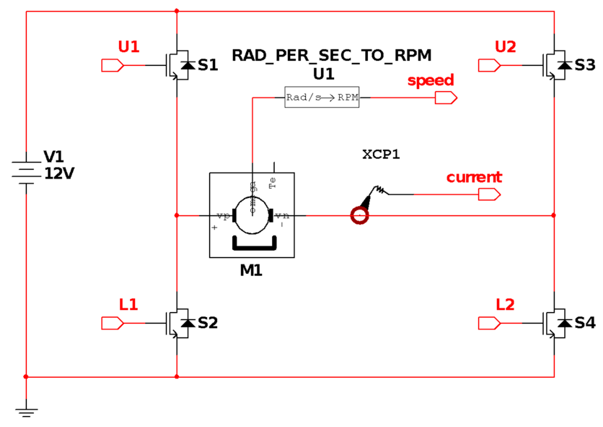
Figure 1) to validate the proposed controller as a previous step for implementing the robust controller in a real target. This co-simulation runs the control system into LabVIEW and the power electronic stage and the DC motor in Multisim, as shown in
Figure 2. The power electronics stage includes the DC motor and power semiconductors that can also be modeled for approaching the experimental ones. Nevertheless, the real DC motor used in the implementation has a gearbox that is a complex system to be completely simulated, because it has several nonlinearities conditions, so only a partial description of it is done under the co-simulation developed in this paper [
46]. The co-simulation and the experimental tests were conducted while using the Per Unit system (P.U.).
Several tests were conducted to validate the proposed robust controller into the co-simulation. The robust controller results were validated against the results from a conventional PID auto-tuning controller [
47].
Figure 3 illustrates the dynamic response of DC motor when the reference speed is 0.27 P.U (per units) and time in seconds (s), and it can be observed that the robust controller has a superior dynamic response against the conventional PID controller, since the permanent steady state of speed is reached around 3E-2 s, and the permanent steady state of speed using the PID controller is reached around 7 E-2 s: Besides, the controller effort is lower in the transitory stage when the robust controller is implemented than the traditional PID controller.
Figure 4 depicts a change in the direction of reference speed, and it can be seen that the dynamic response is also better than the conventional controller, since the motor speed reaches the permanent state in a short time, and also the presented overshoot has a lower magnitude than the PID controller. This kind of performance is quite attractive for applications that require high-speed performance. When the reference speed is equal to 0.57 P.U.
Figure 5, the dynamic response and permanent response of both controllers are quite similar, because the conventional controller response is well when bounded speed inputs are required. Finally,
Figure 6 shows the response of the controllers when an increment equal to 100% of the values of armature inductance and armature resistance were applied in the model of a DC motor. It can be observed that the PID controller requires greater time for achieving the reference speed.
6. Experimental Results
The experimental setup for the validation of the proposed controller is described in the block diagram presented in
Figure 7.
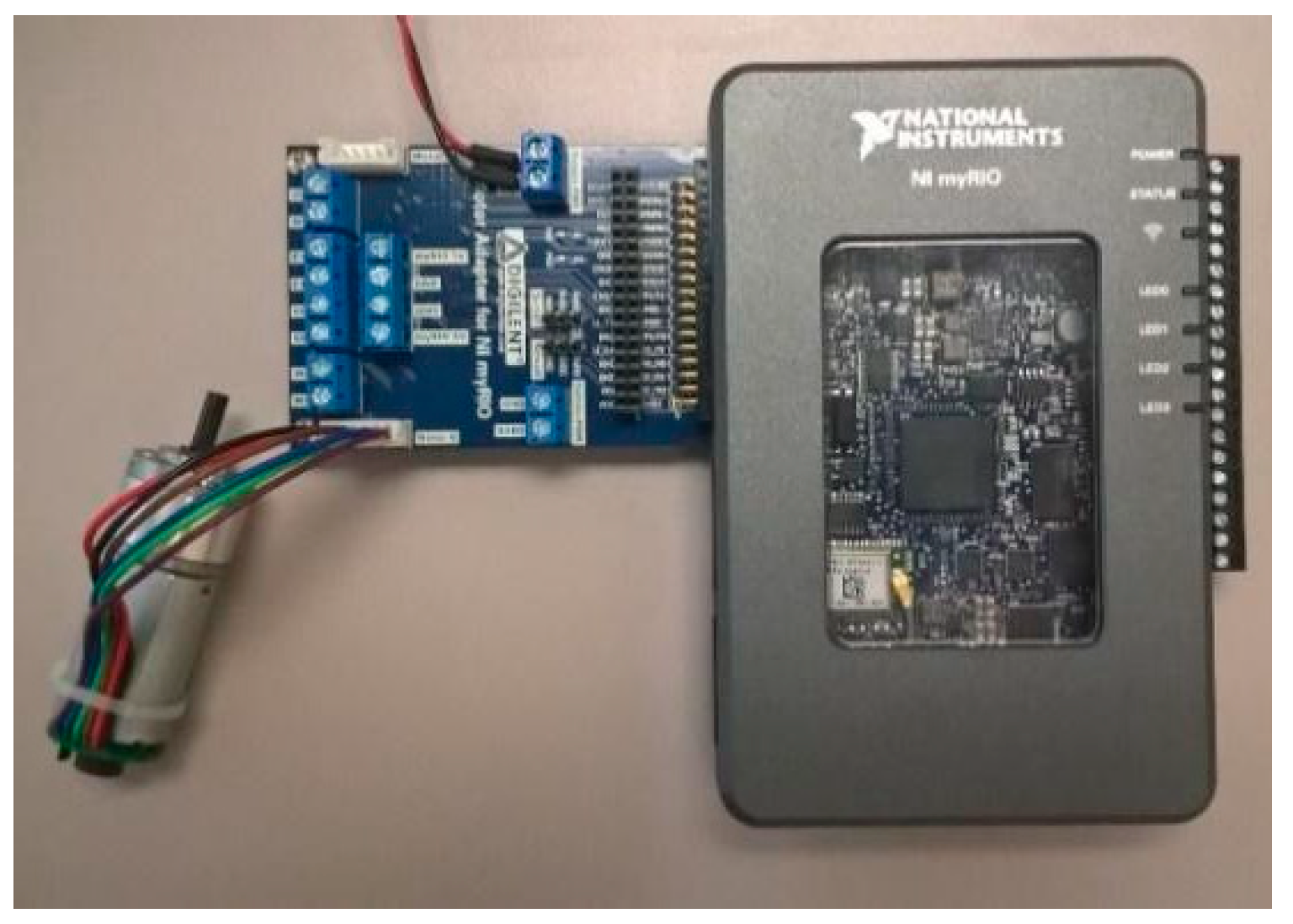
A MyRIO system was selected to run the control algorithms in real-time (see
Figure 8). This digital system is used to implement several control systems to functional prototypes in universities and industries; moreover, it is used in regular engineering classes since it has friendly interface with LabVIEW. It includes ten analog inputs, six analog outputs, 40 digital I/O lines, WiFi, LEDs, a push button, an onboard accelerometer, a Xilinx FPGA, and a dual-core ARM Cortex-A9 processor (National Instruments). The load torque is applied while using another DC motor coupled to the motor shaft that moves in the appositive direction so the load torque can be changed using a PWM (pulse width modulation) technique to apply the desired load torque. The nominal values are: nominal torque = 1.27 [kg/cm], nominal speed 332 (RPM), armature current = 1.47 Amps, Output-power = 4.33 Watts, and Efficiency = 25%.
The power amplifier is a full-bridge developed by AllegroTM that includes the Motor Adapter to NI myRIO. The plant is a 12-V DC motor with an encoder for sensing speed, as well as the electrical/mechanical parameters (see
Section 4.1 for details). The MyRIO digital system and the power amplifier are used in undergraduate engineering classes because they have a friendly interface. Note that the design of the SMC-ON controller does not require knowing the motor’s settings, as shown in
Section 3.
The SMC-ON controller is compared with the widely used PID controller [
48]. The PID can be tuned via LabVIEW’s
PID Autotuning VI, which uses the Ziegler–Nichols method of connecting a relay and an extra feedback signal with the setpoint, providing an auto-tuning procedure. This auto-tuning process guarantees better tuning and robustness against disturbances than the conventional PID-computation methods, since auto-tuning works when the process dynamics or disturbances are unknown (as commonly occurs in real processes). For more details, see PID and Fuzzy Logic Toolkit user manual [
47].
Two tests are reported to validate the proposed SMC-ON controller; both address the regulation of velocity; the first one does not consider the presence of disturbances and the second contains load disturbances.
Figure 9 and
Figure 10 present the responses of the DC motor with PID and SMC-ON controllers, respectively.
Table 1 contains the measure of the regulation errors in terms of the integral squared error and integral time-weighted absolute error for both controllers. As seen, the proposed SMC-ON controller provides a smaller error.
A disturbance of 1.5 times the nominal load is added to the DC motor.
Figure 11 and
Figure 12 show the responses for the disturbance case for PID and SMC-ON. It can be observed that the PID controller is less robust than the proposed one, because the velocity remains closer to the set point compared with the response of the PID controller. Future work could include the comparison of the proposed controller against other sliding mode controllers with different structures, as presented in [
43].
7. Conclusions
In this paper a robust controller was designed and validated using co-simulation and real experiments; co-simulation and MyRIO have been widely used by academia and industry for validating power electronics and control systems so they can create rapid and functional prototypes. However, there are very few papers that present a complete design methodology that can be used by academia and industry to design advanced controllers so this paper also shows a complete robust control design methodology based on well-known software and hardware tools that allows engineering students or industrial designers to create advanced controllers for DC drives, which could be deployed into mechatronics applications such as CNC machines, autonomous cars, robotics and so on. Besides, the paper motivates that engineering students and designers create rapid prototypes.
The proposed robust controller allows for improving the robustness when load torque suddenly appears. Besides, the speed performance of the proposed controller is better than a conventional PID controller, which is the most implemented controller in the industry, so the dynamic response of armature current is also better than using a PID controller, as shown in the co-simulation. Besides, the controller effort is not increased drastically in the robust controller, so the power electronic stage is not affected by thermal increments. Moreover, the proposed controller decrements the chattering in the SMC. In this paper, the Lyapunov stability of DC motor with the controller was evaluated, and a methodology for obtaining the phase and gain margins was also presented and calculated. Two experimental tests, with and without load disturbances, were conducted to demonstrate the capability of being implemented by the proposed controller. The experimental results show that the proposed SMC-ON controller is less sensitive to disturbances and also ensures that the regulation error remains minor. Thus, it is confirmed that this topology can improve the complete performance of the brushed DC motor and open a new control structure that is based on SMC and artificial organic networks. Nevertheless, it is important to mention that it is required to compare the proposed controller against controllers that use adaptive model predictive approaches to have a complete picture of the performance of the proposed controller.


