Enhancing Performance of a Piezoelectric Energy Harvester System for Concurrent Flutter and Vortex-Induced Vibration


Abstract
:
1. Introduction
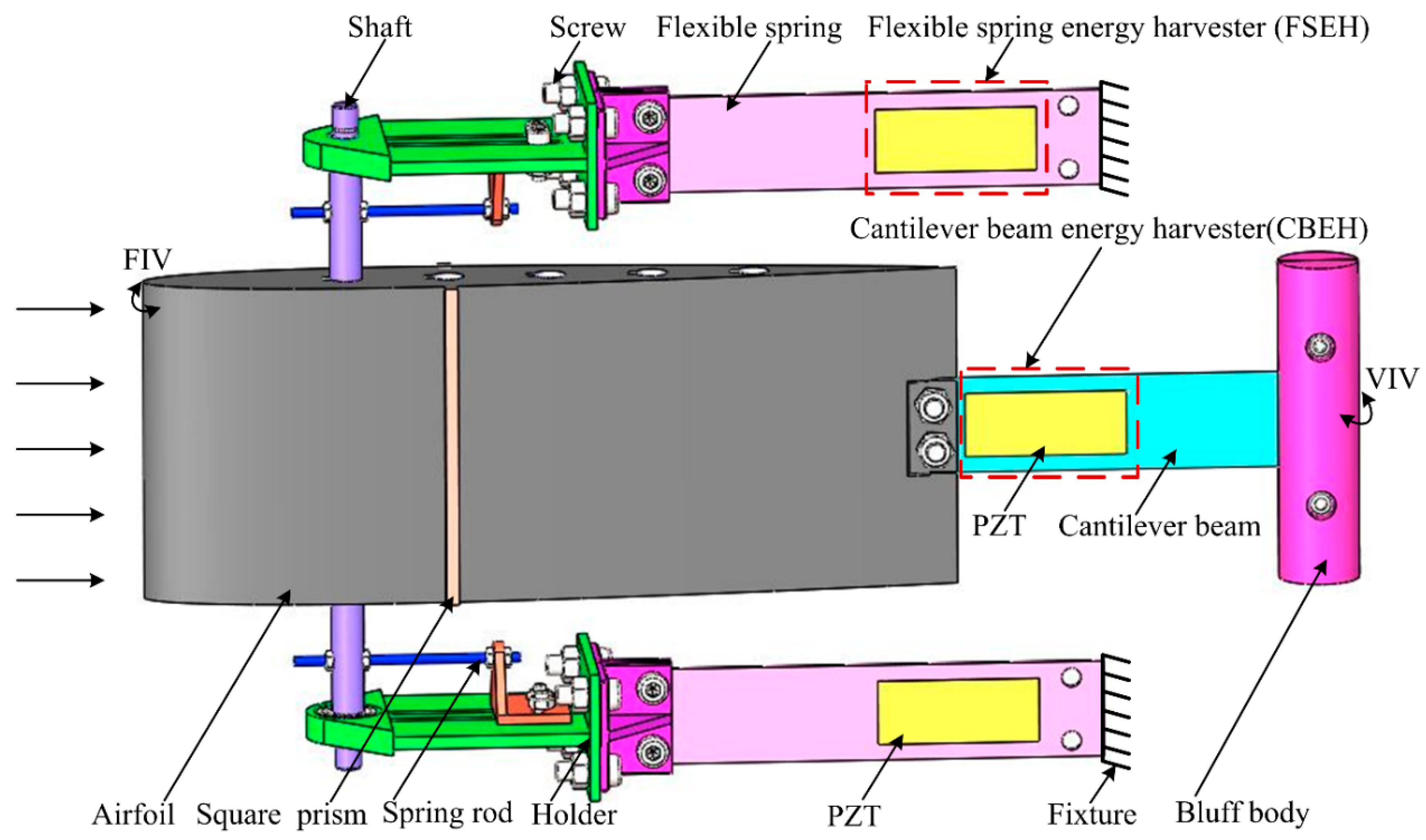
2. Concept and Design of the Piezoelectric Energy Harvester System
3. Experimental Investigation on the Aerodynamic Response and Harvesting Performance
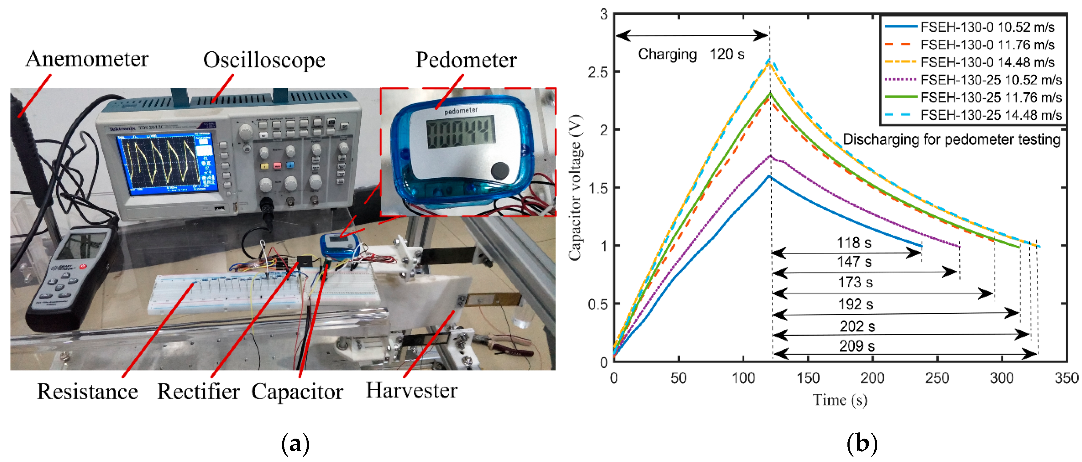
3.1. Experimental Setup of the Harvester System
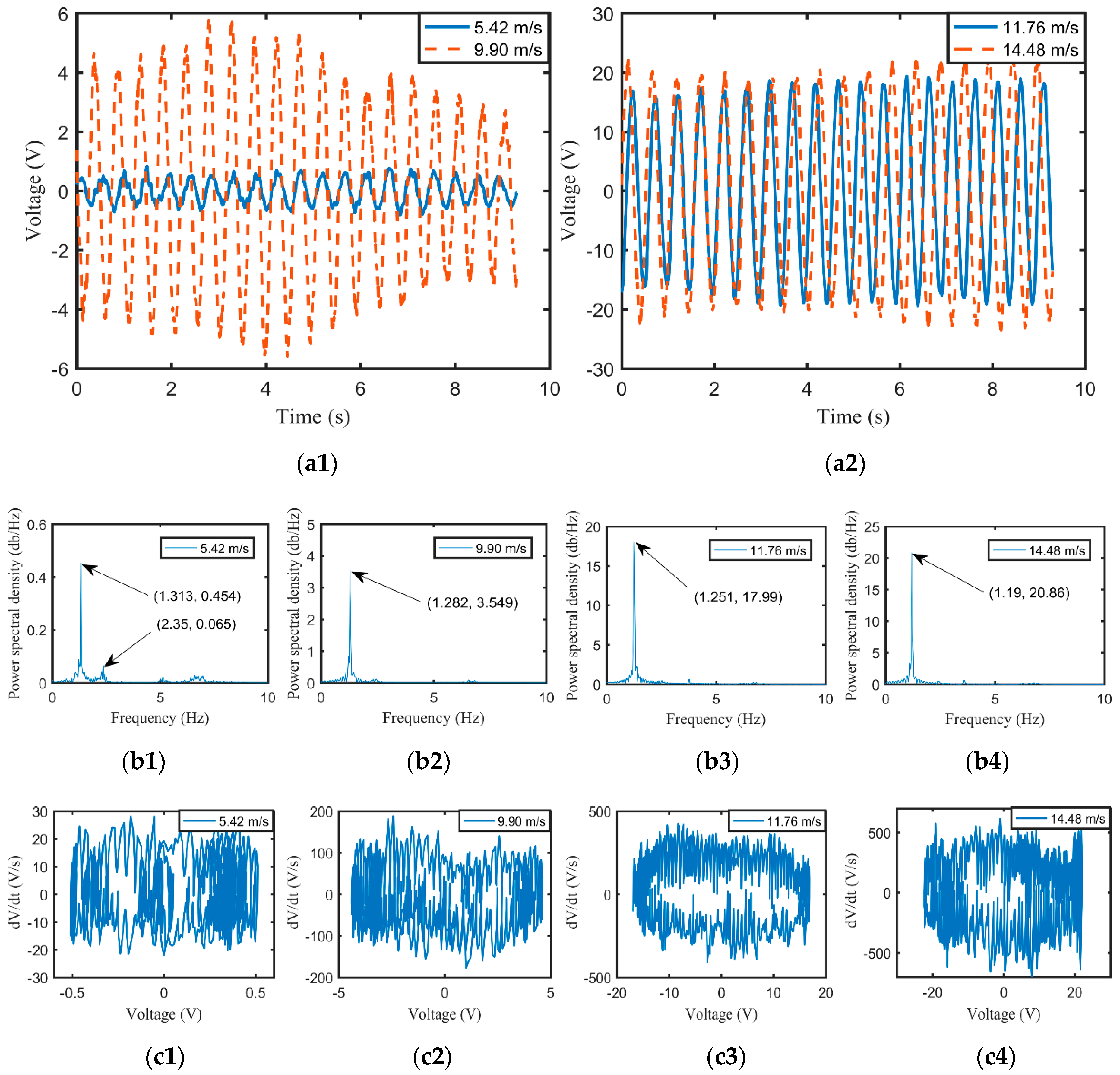
3.2. Aerodynamic Vibration Response of the Harvester System
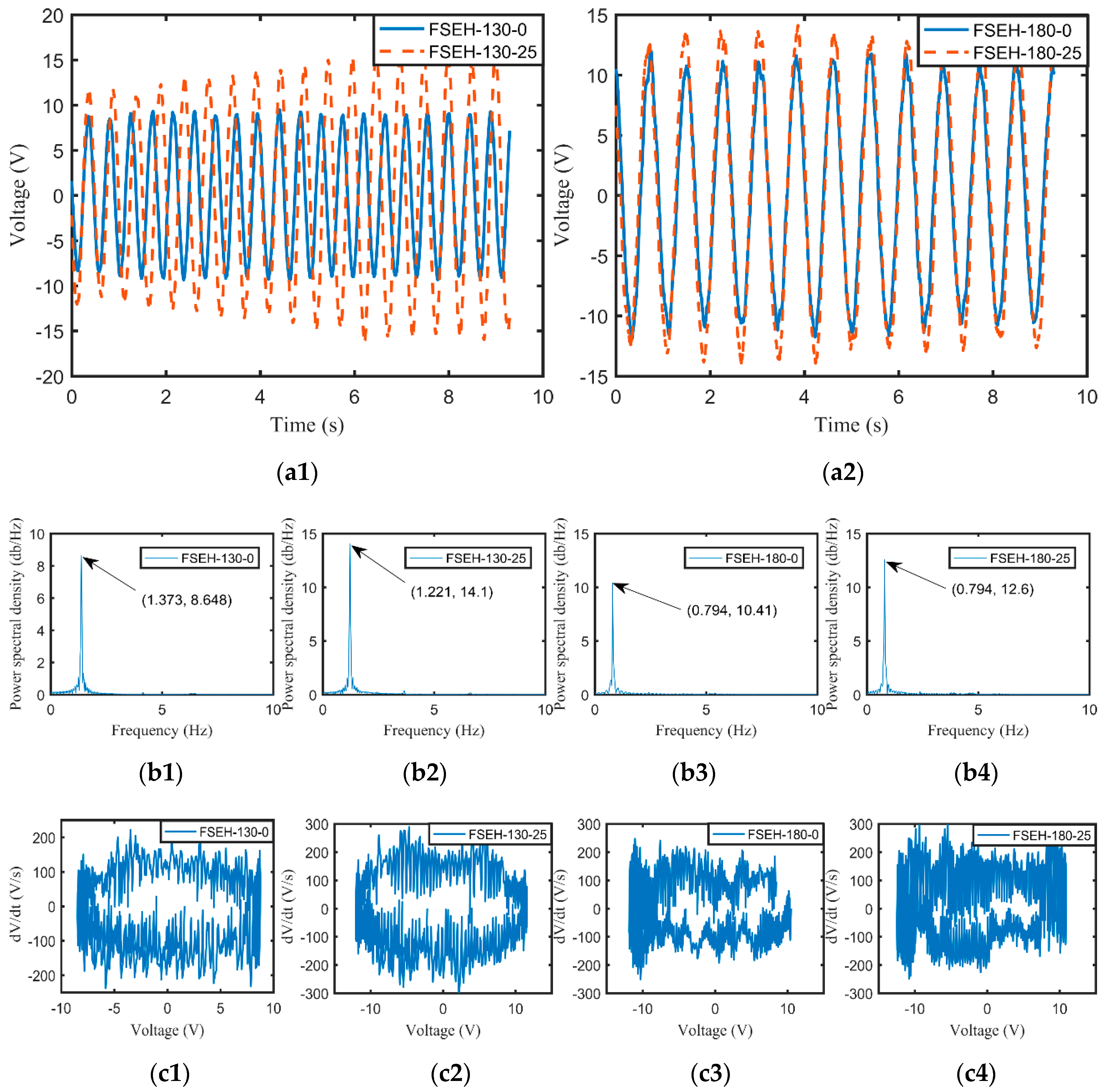
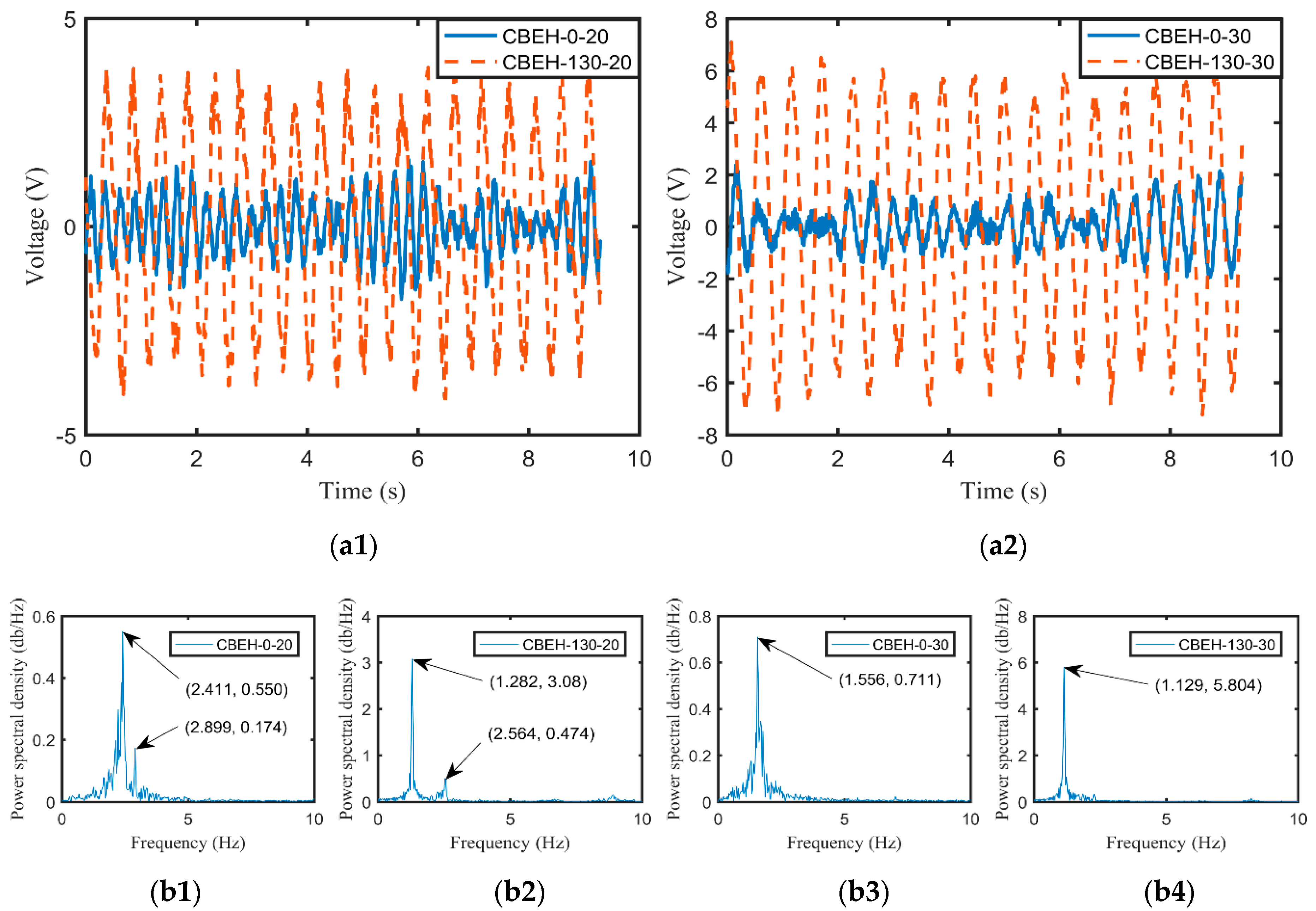
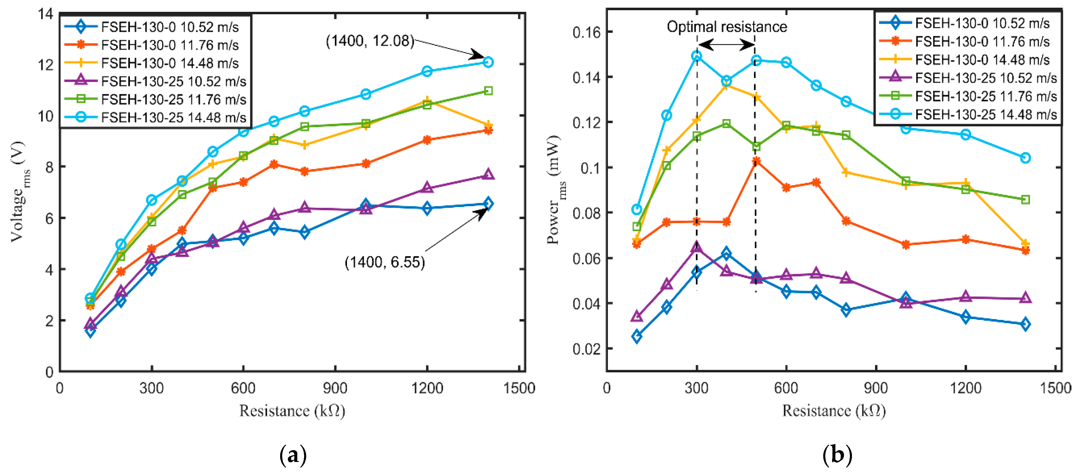
3.3. Harvesting Performance of Various Harvesters
3.4. Coupling Effect Analyses
3.5. Field Application Testing of the Harvester System
3.6. Comparative Analyses
4. Conclusions
- As for FSEH, the longer the flexible spring is, the lower the flutter onset of velocity and critical frequency are, the more likely FIV is to happen, while the VIV easily takes place for CBEH.
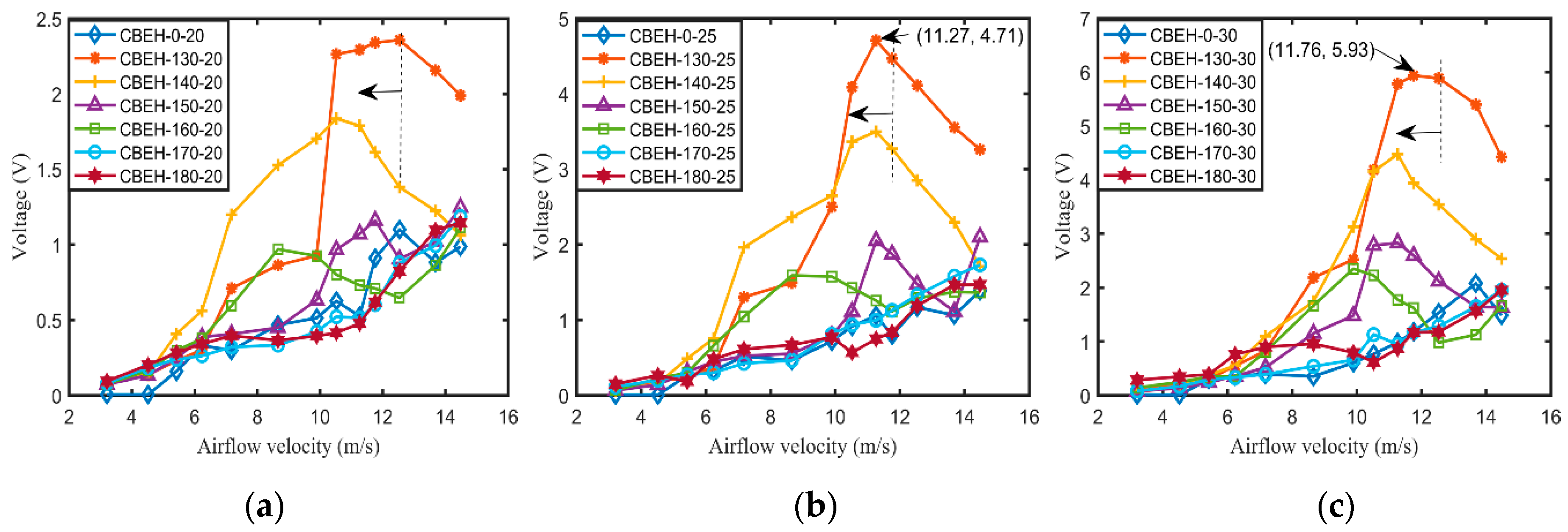
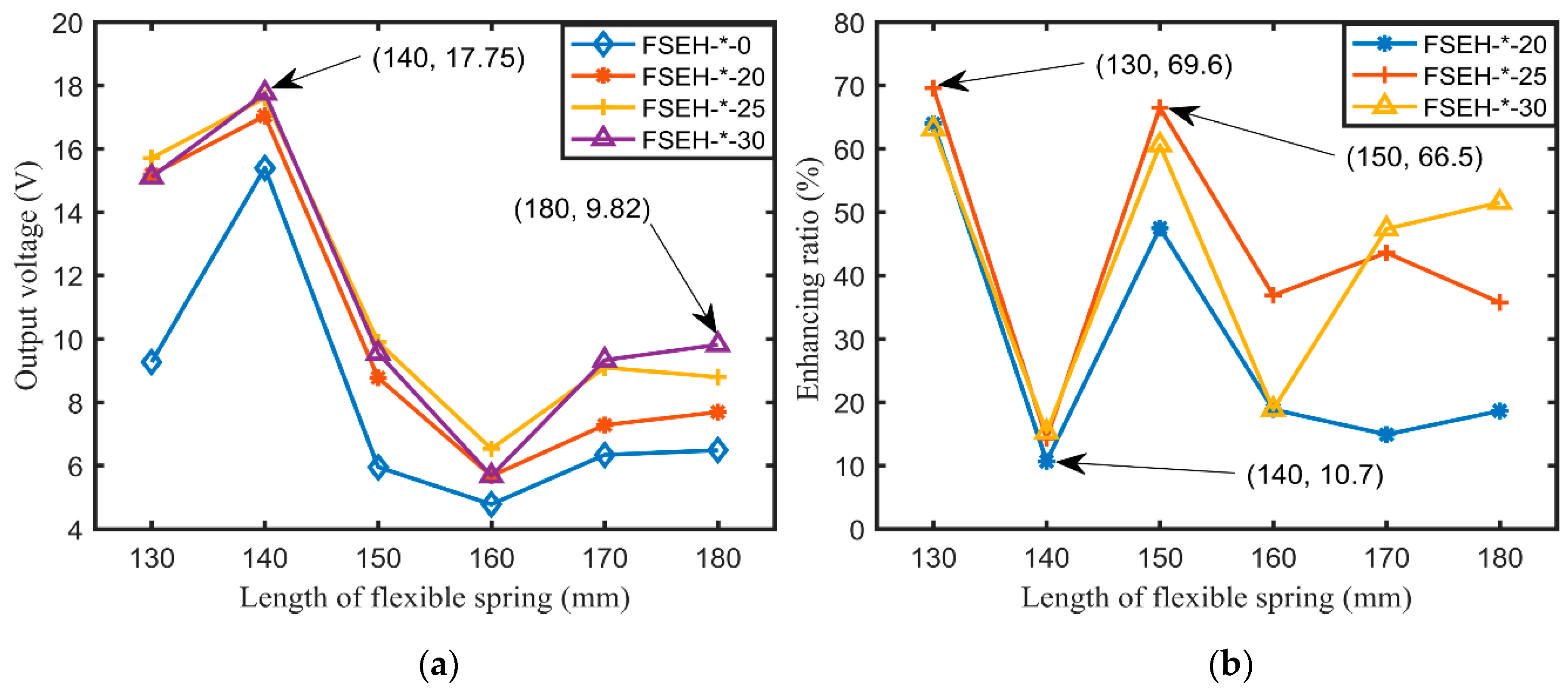
- The vibration response and output performance of various harvesters are mutually enhanced with each other, and the enhancing ratio decreases as the length of the flexible spring increases. The enhancing ratios are up to 69.6% and 198.3% for FSEH-130-25 and CBEH-130-30, respectively.
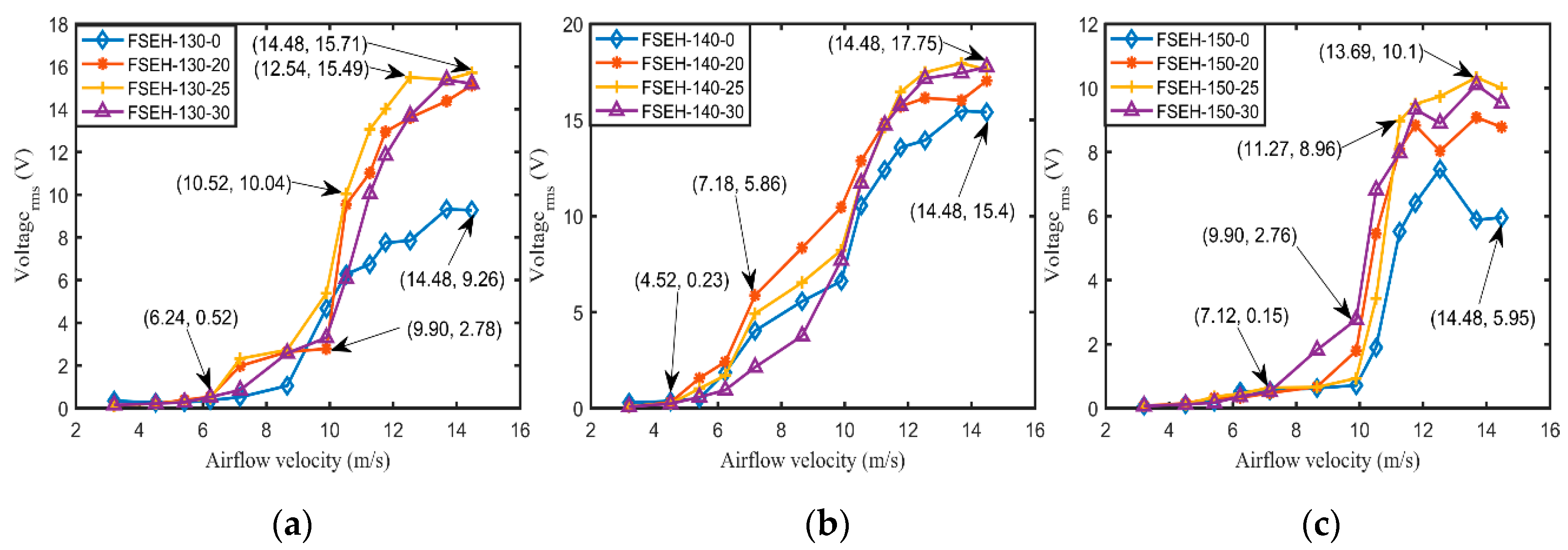
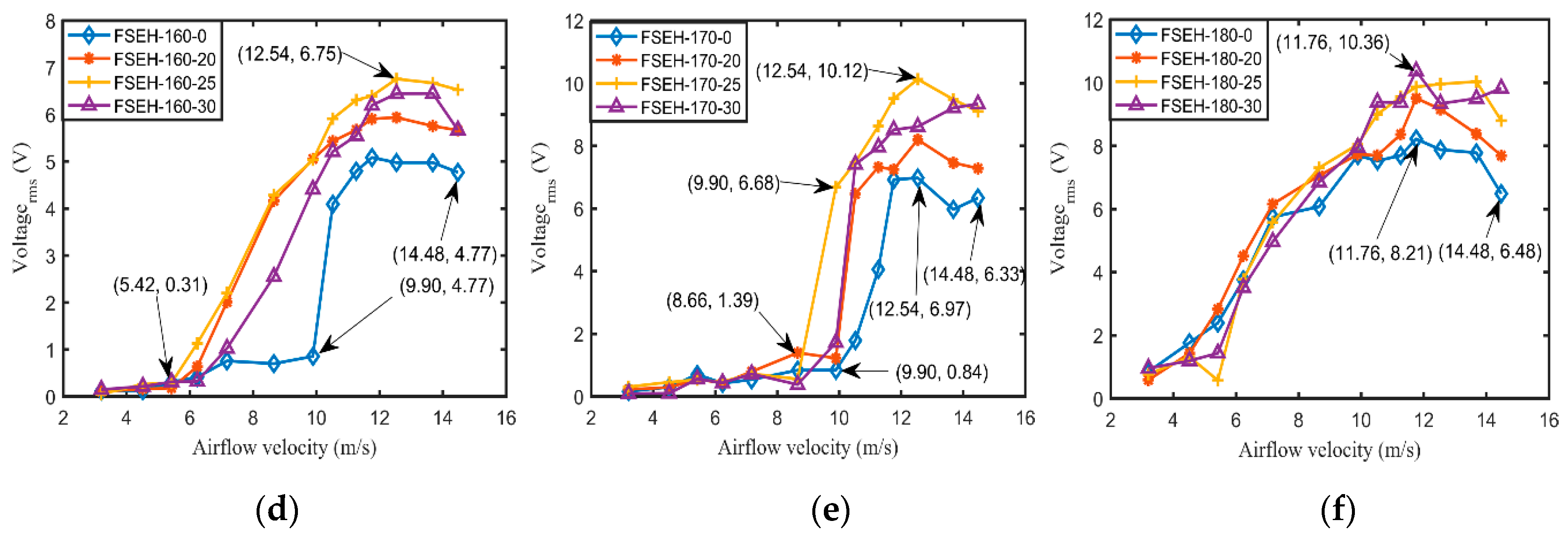
- The output voltage of the harvester first increases rapidly, then flattens gradually, and ultimately decreases with the airflow velocity. As a result, a maximum output voltage of 17.94 V can be harvested for FSEH-140-25 at 13.69 m/s, which is superior to the existing harvesters.
- The field application testing indicated that, when the capacitor charged 120 s via FSEH-130-25 at 14.48 m/s, the discharging time to power the pedometer was up to 207 s, which provides an important experimental guidance for further promotion in the future of practical applications in micro or unmanned airfoil aircrafts.
Author Contributions
Funding
Conflicts of Interest
References
- Yang, Z.; Zhou, S.; Zu, J.; Inman, D.J. High-performance piezoelectric energy harvesters and their applications. Joule 2018, 2, 642–647. [Google Scholar] [CrossRef] [Green Version]
- Zhou, S.; Cao, J.; Inman, D.J.; Lin, J.; Liu, S.; Wang, Z. Broadband tristable energy harvester: Modeling and experiment verification. Appl. Energy 2014, 133, 33–39. [Google Scholar] [CrossRef]
- Lai, Z.; Wang, J.; Zhang, C.; Zhang, G.; Yurchenko, D. Harvest wind energy from a vibro-impact DEG embedded into a bluff body. Energy Convers. Manag. 2019, 199, 111993. [Google Scholar] [CrossRef]
- Xu, S.; Hansen, B.J.; Wang, Z. Piezoelectric-nanowire-enabled power source for driving wireless microelectronics. Nat. Commun. 2010, 1, 93. [Google Scholar] [CrossRef] [PubMed]
- Elahi, H.; Eugeni, M.; Gaudenzi, P. A Review on mechanisms for piezoelectric-based energy harvesters. Energies 2018, 11, 1850. [Google Scholar] [CrossRef] [Green Version]
- Kim, S.; Towfeeq, I.; Dong, Y.; Gorman, S.; Rao, A.M.; Koley, G. P(VDF-TrFE) film on PDMS substrate for energy harvesting applications. Appl. Sci. 2018, 8, 213. [Google Scholar] [CrossRef] [Green Version]
- Evans, M.; Tang, L.; Tao, K.; Aw, K. Design and optimisation of an underfloor energy harvesting system. Sens. Actuators A Phys. 2019, 285, 613–622. [Google Scholar] [CrossRef]
- Briscoe, J.; Dunn, S. Piezoelectric nanogenerators–A review of nanostructured piezoelectric energy harvesters. Nano Energy 2015, 14, 15–29. [Google Scholar] [CrossRef]
- Zhou, S.; Cao, J.; Erturk, A.; Lin, J. Enhanced broadband piezoelectric energy harvesting using rotatable magnets. Appl. Phys. Lett. 2013, 102, 173901. [Google Scholar] [CrossRef] [Green Version]
- Fan, K.; Liu, S.; Liu, H.; Zhu, Y.; Wang, W.; Zhang, D. Scavenging energy from ultra-low frequency mechanical excitations through a bi-directional hybrid energy harvester. Appl. Energy 2018, 216, 8–20. [Google Scholar] [CrossRef]
- Xu, Z.; Wang, W.; Xie, J.; Xu, Z.; Zhou, M.; Yang, H. An impact-based frequency up-converting hybrid vibration energy harvester for low frequency application. Energies 2017, 10, 1761. [Google Scholar] [CrossRef] [Green Version]
- Zhang, Y.; Wang, T.; Luo, A.; Hu, Y.; Li, X.; Wang, F. Micro electrostatic energy harvester with both broad bandwidth and high normalized power density. Appl. Energy 2018, 212, 362–371. [Google Scholar] [CrossRef]
- Zhao, L.; Chen, K.; Yang, F.; Zheng, M.; Guo, J.; Gu, G.; Zhang, B.; Qin, H.; Cheng, G.; Du, Z. The novel transistor and photodetector of monolayer MoS2 based on surface-ionic-gate modulation powered by a triboelectric nanogenerator. Nano Energy 2019, 62, 38–45. [Google Scholar] [CrossRef]
- Liu, Y.; Chen, W.; Liu, J.; Shi, S. A rectangle-type linear ultrasonic motor using longitudinal vibration transducers with four driving feet. IEEE Trans. Ultrason. Ferroelectr. Freq. Control. 2013, 60, 777–785. [Google Scholar] [CrossRef]
- Liu, Y.; Liu, J.; Chen, W.; Shi, S. A u-shaped linear ultrasonic motor using longitudinal vibration transducers with double feet. IEEE Trans. Ultrason. Ferroelectr. Freq. Control. 2012, 59, 981–989. [Google Scholar] [CrossRef]
- Xie, X.; Wang, Q. Energy harvesting from a vehicle suspension system. Energy 2015, 86, 385–392. [Google Scholar] [CrossRef]
- Naseer, R.; Dai, H.; Abdelkefi, A.; Wang, L. Piezomagnetoelastic energy harvesting from vortex-induced vibrations using monostable characteristics. Appl. Energy 2017, 203, 142–153. [Google Scholar] [CrossRef]
- Zhang, L.; Dai, H.; Abdelkefi, A.; Wang, L. Experimental investigation of aerodynamic energy harvester with different interference cylinder cross-sections. Energy 2019, 167, 970–981. [Google Scholar] [CrossRef]
- Wang, J.; Geng, L.; Zhang, M.; Zhao, G.; Zhang, M.; Zhang, Z.; Li, Y. Broadening band of wind speed for aeroelastic energy scavenging of a cylinder through buffeting in the wakes of a squared prism. Shock. Vib. 2018, 2018, 1–14. [Google Scholar] [CrossRef]
- Shan, X.; Li, H.; Yang, Y.; Feng, J.; Wang, Y.; Xie, T. Enhancing the performance of an underwater piezoelectric energy harvester based on flow-induced vibration. Energy 2019, 172, 134–140. [Google Scholar] [CrossRef]
- Zhao, L.; Yang, Y. An impact-based broadband aeroelastic energy harvester for concurrent wind and base vibration energy harvesting. Appl. Energy 2018, 212, 233–243. [Google Scholar] [CrossRef]
- Wang, J.; Tang, L.; Zhao, L.; Zhang, Z. Efficiency investigation on energy harvesting from airflows in HVAC system based on galloping of isosceles triangle sectioned bluff bodies. Energy 2019, 172, 1066–1078. [Google Scholar] [CrossRef]
- Usman, M.; Hanif, A.; Kim, I.-H.; Jung, H.-J. Experimental validation of a novel piezoelectric energy harvesting system employing wake galloping phenomenon for a broad wind spectrum. Energy 2018, 153, 882–889. [Google Scholar] [CrossRef]
- Olivieri, S.; Boccalero, G.; Mazzino, A.; Boragno, C. Fluttering conditions of an energy harvester for autonomous powering. Renew. Energy 2017, 105, 530–538. [Google Scholar] [CrossRef]
- St. Clair, D.; Bibo, A.; Sennakesavababu, V.R.; Daqaq, M.F.; Li, G. A scalable concept for micropower generation using flow-induced self-excited oscillations. Appl. Phys. Lett. 2010, 96, 144103. [Google Scholar] [CrossRef]
- Andrianne, T.; Aryoputro, R.; Laurent, P.; Colson, G.; Amandolèse, X.; Hémon, P. Energy harvesting from different aeroelastic instabilities of a square cylinder. J. Wind. Eng. Ind. Aerodyn. 2018, 172, 164–169. [Google Scholar] [CrossRef]
- De Marqui, C.; Tan, D.; Erturk, A. On the electrode segmentation for piezoelectric energy harvesting from nonlinear limit cycle oscillations in axial flow. J. Fluids Struct. 2018, 82, 492–504. [Google Scholar] [CrossRef]
- Kwon, S. A T-shaped piezoelectric cantilever for fluid energy harvesting. Appl. Phys. Lett. 2010, 97, 164102. [Google Scholar] [CrossRef]
- Aquino, A.I.; Calautit, J.K.; Hughes, B.R. Evaluation of the integration of the Wind-Induced Flutter Energy Harvester (WIFEH) into the built environment: Experimental and numerical analysis. Appl. Energy 2017, 207, 61–77. [Google Scholar] [CrossRef]
- Zhao, L.; Yang, Y. Enhanced aeroelastic energy harvesting with a beam stiffener. Smart Mater. Struct. 2015, 24, 032001. [Google Scholar] [CrossRef]
- Dunnmon, J.A.; Stanton, S.C.; Mann, B.P.; Dowell, E.H. Power extraction from aeroelastic limit cycle oscillations. J. Fluids Struct. 2011, 27, 1182–1198. [Google Scholar] [CrossRef]
- Zakaria, M.Y.; Al-Haik, M.Y.; Hajj, M.R. Experimental analysis of energy harvesting from self-induced flutter of a composite beam. Appl. Phys. Lett. 2015, 107, 023901. [Google Scholar] [CrossRef]
- Wu, Y.; Li, D.; Xiang, J.; Da Ronch, A. Piezoaeroelastic energy harvesting based on an airfoil with double plunge degrees of freedom: Modeling and numerical analysis. J. Fluids Struct. 2017, 74, 111–129. [Google Scholar] [CrossRef]
- Erturk, A.; Vieira, W.; De Marqui, C.; Inman, D.J. On the energy harvesting potential of piezoaeroelastic systems. Appl. Phys. Lett. 2010, 96, 184103. [Google Scholar] [CrossRef]
- Gibbs, S.C.; Wang, I.; Dowell, E. Theory and experiment for flutter of a rectangular plate with a fixed leading edge in three-dimensional axial flow. J. Fluids Struct. 2012, 34, 68–83. [Google Scholar] [CrossRef]
- Tang, D.M.; Yamamoto, H.; Dowell, E.H. Flutter and limit cycle oscillations of two-dimensional panels in three-dimensional axial flow. J. Fluids Struct. 2003, 17, 225–242. [Google Scholar] [CrossRef]
- Shan, X.; Tian, H.; Chen, D.; Xie, T. A curved panel energy harvester for aeroelastic vibration. Appl. Energy 2019, 249, 58–66. [Google Scholar] [CrossRef]
- Wang, Y.; Inman, D.J. Simultaneous energy harvesting and gust alleviation for a multifunctional composite wing spar using reduced energy control via piezoceramics. J. Compos. Mater. 2013, 47, 125–146. [Google Scholar] [CrossRef]
- Wang, Y.; Inman, D.J. Experimental characterization of simultaneous gust alleviation and energy harvesting for multifunctional wing spars. Proc. Spie. 2012, 4, 834114. [Google Scholar] [CrossRef]
- Orrego, S.; Shoele, K.; Ruas, A.; Doran, K.; Caggiano, B.; Mittal, R.; Kang, S.H. Harvesting ambient wind energy with an inverted piezoelectric flag. Appl. Energy 2017, 194, 212–222. [Google Scholar] [CrossRef]
- Dias, J.; De Marqui, C.; Erturk, A. Hybrid piezoelectric-inductive flow energy harvesting and dimensionless electroaeroelastic analysis for scaling. Appl. Phys. Lett. 2013, 102, 044101. [Google Scholar] [CrossRef] [Green Version]
- Vasconcellos, R.; Abdelkefi, A. Nonlinear dynamical analysis of an aeroelastic system with multi-segmented moment in the pitch degree-of-freedom. Commun. Nonlinear Sci. Numer. Simult. 2015, 20, 324–334. [Google Scholar] [CrossRef]
- De Sousa, V.C.; Junior, C.D.M. Airfoil-based piezoelectric energy harvesting by exploiting the pseudoelastic hysteresis of shape memory alloy springs. Smart Mater. Struct. 2015, 24, 125014. [Google Scholar] [CrossRef]
- Liu, H.; Gao, X. Vibration energy harvesting under concurrent base and flow excitations with internal resonance. Nonlinear Dyn. 2019, 96, 1067–1081. [Google Scholar] [CrossRef]
- Elahi, H.; Eugeni, M.; Gaudenzi, P. Design and performance evaluation of a piezoelectric aeroelastic energy harvester based on the limit cycle oscillation phenomenon. Acta Astronaut. 2019, 157, 233–240. [Google Scholar] [CrossRef]
- Wu, Y.; Li, D.; Xiang, J. Dimensionless modeling and nonlinear analysis of a coupled pitch–plunge–leadlag airfoil-based piezoaeroelastic energy harvesting system. Nonlinear Dyn. 2018, 92, 153–167. [Google Scholar] [CrossRef]
- Abdelkefi, A.; Nuhait, A.O. Modeling and performance analysis of cambered wing-based piezoaeroelastic energy harvesters. Smart Mater. Struct. 2013, 22, 095029. [Google Scholar] [CrossRef]
- Wang, E.; Ramesh, K.; Killen, S.; Viola, I.M. On the nonlinear dynamics of self-sustained limit-cycle oscillations in a flapping-foil energy harvester. J. Fluids Struct. 2018, 83, 339–357. [Google Scholar] [CrossRef] [Green Version]
- Zhou, Z.; Qin, W.; Zhu, P.; Du, W.; Deng, W.; Pan, J. Scavenging wind energy by a dynamic-stable flutter energy harvester with rectangular wing. Appl. Phys. Lett. 2019, 114, 243902. [Google Scholar] [CrossRef]
- Bibo, A.; Abdelkefi, A.; Daqaq, M.F. Modeling and characterization of a piezoelectric energy harvester under combined aerodynamic and base excitations. J. Vib. Acoust. 2015, 137, 031017. [Google Scholar] [CrossRef]
- Muhammad, I.; Ullah, K.F. Hybrid vibration and wind energy harvesting using combined piezoelectric and electromagnetic conversion for bridge health monitoring applications. Energy Convers. Manag. 2018, 172, 611–618. [Google Scholar] [CrossRef]
- Abdelkefi, A.; Hajj, M.R. Performance enhancement of wing-based piezoaeroelastic energy harvesting through freeplay nonlinearity. Theor. Appl. Mech. Lett. 2013, 3, 041001. [Google Scholar] [CrossRef] [Green Version]
- Abdelkefi, A.; Nayfeh, A.H.; Hajj, M.R. Enhancement of power harvesting from piezoaeroelastic systems. Nonlinear Dyn. 2012, 68, 531–541. [Google Scholar] [CrossRef]
- Zhou, Z.; Qin, W.; Zhu, P.; Shang, S. Scavenging wind energy by a Y-shaped bi-stable energy harvester with curved wings. Energy 2018, 153, 400–412. [Google Scholar] [CrossRef] [Green Version]
- Li, K.; Yang, Z.; Gu, Y.; He, S.; Zhou, S. Nonlinear magnetic-coupled flutter-based aeroelastic energy harvester: Modeling, simulation and experimental verification. Smart Mater. Struct. 2019, 28, 015020. [Google Scholar] [CrossRef] [Green Version]
- Sousa, V.C.; de M Anicézio, M.; De Marqui, C., Jr.; Erturk, A. Enhanced aeroelastic energy harvesting by exploiting combined nonlinearities: Theory and experiment. Smart Mater. Struct. 2011, 20, 094007. [Google Scholar] [CrossRef]
- Bibo, A.; Daqaq, M.F. Investigation of concurrent energy harvesting from ambient vibrations and wind using a single piezoelectric generator. Appl. Phys. Lett. 2013, 102, 243904. [Google Scholar] [CrossRef] [Green Version]
- Cheng, T.; Fu, X.; Liu, W.; Lu, X.; Chen, X.; Wang, Y.; Bao, G. Airfoil-based cantilevered polyvinylidene fluoride layer generator for translating amplified air-flow energy. Renew. Energy 2019, 135, 399–407. [Google Scholar] [CrossRef]
- Erturk, A.; Bilgen, O.; Fontenille, M.; Inman, D.J. Piezoelectric energy harvesting from macro-fiber composites with an application to morphing-wing aircrafts. In Proceedings of the 19th International Conference on Adaptive Structures and Technologies, Ascona, Switzerland, 6–9 October 2008; pp. 1–21. [Google Scholar]


| Properties | Flexible Spring | Piezoelectric Patch | Cantilever Beam | Bluff Body |
|---|---|---|---|---|
| Materials | Spring steel | PZT-5H | Copper | Acrylic |
| Density, ρ (kg/m3) | 7850 | 7500 | 8900 | 1190 |
| Modulus, E (GPa) | 210 | 66 | 105 | 30 |
| Poisson’s ratio, v | 0.29 | 0.3 | 0.35 | 0.39 |
| Length, l (mm) | 130–180 | 40 | 100 | 100 |
| Width/Diameter, (mm) | 30 | 20 | 30 | 20–30 |
| Thickness, h (mm) | 0.5 | 0.2 | 0.25 | - |
| Mass, m (g) | 16–21 | 5 | 14 | 44–84 |
| Permittivity, ε (nF/m) | - | 13 | - | - |
| Piezoelectric, d31 (C/N) | - | −274 | - | - |
| Properties | Airfoil |
|---|---|
| Materials | PLA |
| Density, ρ (kg/m3) | 1250 |
| Modulus, E (GPa) | 3.5 |
| Harvester mass, mT (g) | 540 |
| Airfoil mass, m (g) | 380 |
| Span, s (mm) | 100 |
| Semi-chord, b (mm) | 126 |
| Names | FSEH-180-20 | FSEH-180-0 | CBEH-180-20 | CBEH-0-20 |
|---|---|---|---|---|
| Length of flexible spring | 180 | 180 | 180 | - |
| Airfoil motion pattern | Mobile | Mobile | Mobile | Fixed |
| Diameter of bluff body | 20 | - | 20 | 20 |
| Reference | Mechanism | Airflow Velocity (m/s) | Average Power (μW) | Power Density (μW/cm2) | Power Density (μW/cm3) | Configuration |
|---|---|---|---|---|---|---|
| Abdelkefi et al. [52] | Piezoelectric | 12.59 | 300 | - | - |  |
| Iqbal et al. [51] | Electromagnetic–piezoelectric | 6 | 11.2 | 0.16 | 0.04 |  |
| Cheng et al. [58] | Piezoelectric | 42.4 | 13.06 | - | - | 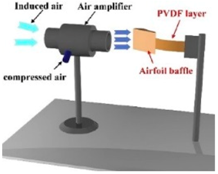 |
| Erturk et al. [59] | Piezoelectric | 15 | 7 | 0.04 | - | 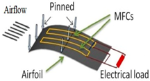 |
| This work | Piezoelectric | 14.48 | 154 | 2.41 | 0.48 | 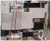 |
© 2020 by the authors. Licensee MDPI, Basel, Switzerland. This article is an open access article distributed under the terms and conditions of the Creative Commons Attribution (CC BY) license (http://creativecommons.org/licenses/by/4.0/).
Share and Cite
Shan, X.; Tian, H.; Cao, H.; Xie, T. Enhancing Performance of a Piezoelectric Energy Harvester System for Concurrent Flutter and Vortex-Induced Vibration. Energies 2020, 13, 3101. https://doi.org/10.3390/en13123101
Shan X, Tian H, Cao H, Xie T. Enhancing Performance of a Piezoelectric Energy Harvester System for Concurrent Flutter and Vortex-Induced Vibration. Energies. 2020; 13(12):3101. https://doi.org/10.3390/en13123101
Chicago/Turabian StyleShan, Xiaobiao, Haigang Tian, Han Cao, and Tao Xie. 2020. "Enhancing Performance of a Piezoelectric Energy Harvester System for Concurrent Flutter and Vortex-Induced Vibration" Energies 13, no. 12: 3101. https://doi.org/10.3390/en13123101