Article

Artificial Intelligence-Based Weighting Factor Autotuning for Model Predictive Control of Grid-Tied Packed U-Cell Inverter

by
Mostefa Mohamed-Seghir
1,
Abdelbasset Krama
2,3,
Shady S. Refaat
3,*,
Mohamed Trabelsi
3,4 and
Haitham Abu-Rub
3
1
Faculty of Electrical Engineering, Gdynia Maritime University, 81-225 Gdynia, Poland
2
LEVRES Laboratory, The University of El-Oued, Fac. Technology, El-Oued 39000, Algeria
3
Department of Electrical and Computer Engineering, Texas A&M University at Qatar, Qatar Foundation, Doha, PO Box 23874, Qatar
4
Department of Electronic and Communications Engineering, Kuwait College of Science and Technology, Doha, P.O. Box 27235, Kuwait
*
Author to whom correspondence should be addressed.
Energies 2020, 13(12), 3107; https://doi.org/10.3390/en13123107
Submission received: 14 May 2020 / Revised: 10 June 2020 / Accepted: 11 June 2020 / Published: 16 June 2020
(This article belongs to the Section F: Electrical Engineering)

Abstract

:
The tuning of weighting factor has been considered as the most challenging task in the implementation of multi-objective model predictive control (MPC) techniques. Thus, this paper proposes an artificial intelligence (AI)-based weighting factor autotuning in the design of a finite control set MPC (FCS-MPC) applied to a grid-tied seven-level packed U-cell (PUC7) multilevel inverter (MLI). The studied topology is capable of producing a seven-level output voltage waveform and inject sinusoidal current to the grid with high power quality while using a reduced number of components. The proposed cost function optimization algorithm ensures auto-adjustment of the weighting factor to guarantee low injected grid current total harmonic distortion (THD) at different power ratings while balancing the capacitor voltage. The optimal weighting factor value is selected at each sampling time to guarantee a stable operation of the PUC inverter with high power quality. The weighting factor selection is performed using an artificial neural network (ANN) based on the measured injected grid current. Simulation and experimental results are presented to show the high performance of the proposed strategy in handling multi-objective control problems.

Graphical Abstract

1. Introduction

Multilevel inverters (MLIs) have been widely used in interruptible power supplies, renewable energy integration, and motor drive applications due to their high power quality, reduced switching losses, higher number of levels (better voltage waveform), and possible operation in high power applications [1,2].
Various MLI topologies have been reported in the literature for different applications [1,3,4,5,6,7,8]. Recently, the packed U-cell (PUC) inverter has been considered as one of the most interesting single DC source MLI topologies due to its high reliability (reduced number of active and passive elements), high power quality, and large multilevel voltage synthesis versatility [9,10,11]. However, the effective operation of the PUC inverter depends mainly on the appropriate selection of the switching patterns to guarantee high tracking accuracy of the state variables and minimization of the switching losses. When a proportional–integral (PI) controller is used, the inclusion of the system nonlinearities becomes a major problem. Model predictive control (MPC) has been considered as a promising alternative to standard controllers, especially in the presence of system nonlinearities [12,13].
Thus, MPC is one of the most interesting control methods for MLIs as it combines the discrete characteristic of the controller in a simple way with the discrete characteristic of the converter [14,15,16,17]. In [18,19,20,21], a finite control set MPC (FCS-MPC) was proposed as an optimized control solution to achieve good dynamic performance using an optimized cost function. However, one of the greatest technical challenges in the design of the MPC algorithm is the determination of appropriate weighting factors to obtain the desired control objectives.
The best sellection of the cost function is a challenging task, where a bad design could lead to system instability. In this context, trial and error techniques have been mostly used for selection of the most suitable weighting factor that can lead to the aimed control performance [19]. However, these techniques are time-consuming and noneffective when applied at different operational conditions in which the selected weighting factor could be optimized locally. In order to decrease the computation time, a branch-and-bound method was investigated in [22], where the weighting factor is selected empirically. The study in [23] proposed a recursive multicriteria optimization algorithm for the tuning of the weighting factors. The authors in [24] proposed a weighting factor optimization technique based on estimation of the absolute error of the state variable tracking. In [25], an adaptation strategy of online weighting factors was presented using an analytical variant. However, the proposed method has no constraint on the average switching frequency, which may be unrealistic due to the long calculation time.
Recently, several research works based on artificial intelligence (AI) have been proposed to overcome this problem, including artificial neural network (ANN), genetic algorithms (GA), particle swarm optimization (PSO), and fuzzy logic (FL) [26,27,28,29,30,31,32,33,34]. The authors in [29] used an ANN to determine automatically the weighting factor in the FCS-MPC proposed for a regulated uninterruptable power supply (UPS) converter to guarantee minimization of the total harmonic distortion (THD) and the switching frequency. The authors in [30] used multi-objective evolutionary algorithms (MOEA). In [31], a multi-objective genetic algorithm (MOGA) was proposed to design parameters and optimize two weighting factors within a FCS-MPC with a bypass active power filter. To adjust the distributed MPC weighting factors controlling the power system, the authors used PSO in [32]. To choose the right control action at each stage of the MPC algorithm, the authors in [33] included the GA. In [34], the MOGA was used to obtain a set of appropriate weighting factors to be used in induction motor-based MPC. The authors focused mainly on the simultaneous tuning of many weighting factors, where the proposed control took into account the inverter average switching frequency, the torque, and the flux of the induction motor.
In the present work, a new technique for selecting the optimized weighting factor value in the FCS-MPC strategy is presented and applied for a grid-connected seven-level PUC (PUC7) MLI. The main contribution of this work is the selection of the best weighting factor based on an ANN technique to ensure stable and robust operation of the studied PUC7 MLI under different operating conditions while reducing the THD of the grid current and the capacitor voltage error.
The remainder of this work is structured as follows. Section 2 explains the modeling and operational principle of the studied PUC7 inverter and the proposed control approach. In Section 3, the proposed ANN-based algorithm for autotuning of the weighting factor is detailed. In Section 4, the simulation results are provided and discussed. Section 5 presents the experimental results and discusses validation of the proposed control technique, while some conclusions are drawn in Section 6.

2. Theoretical Study

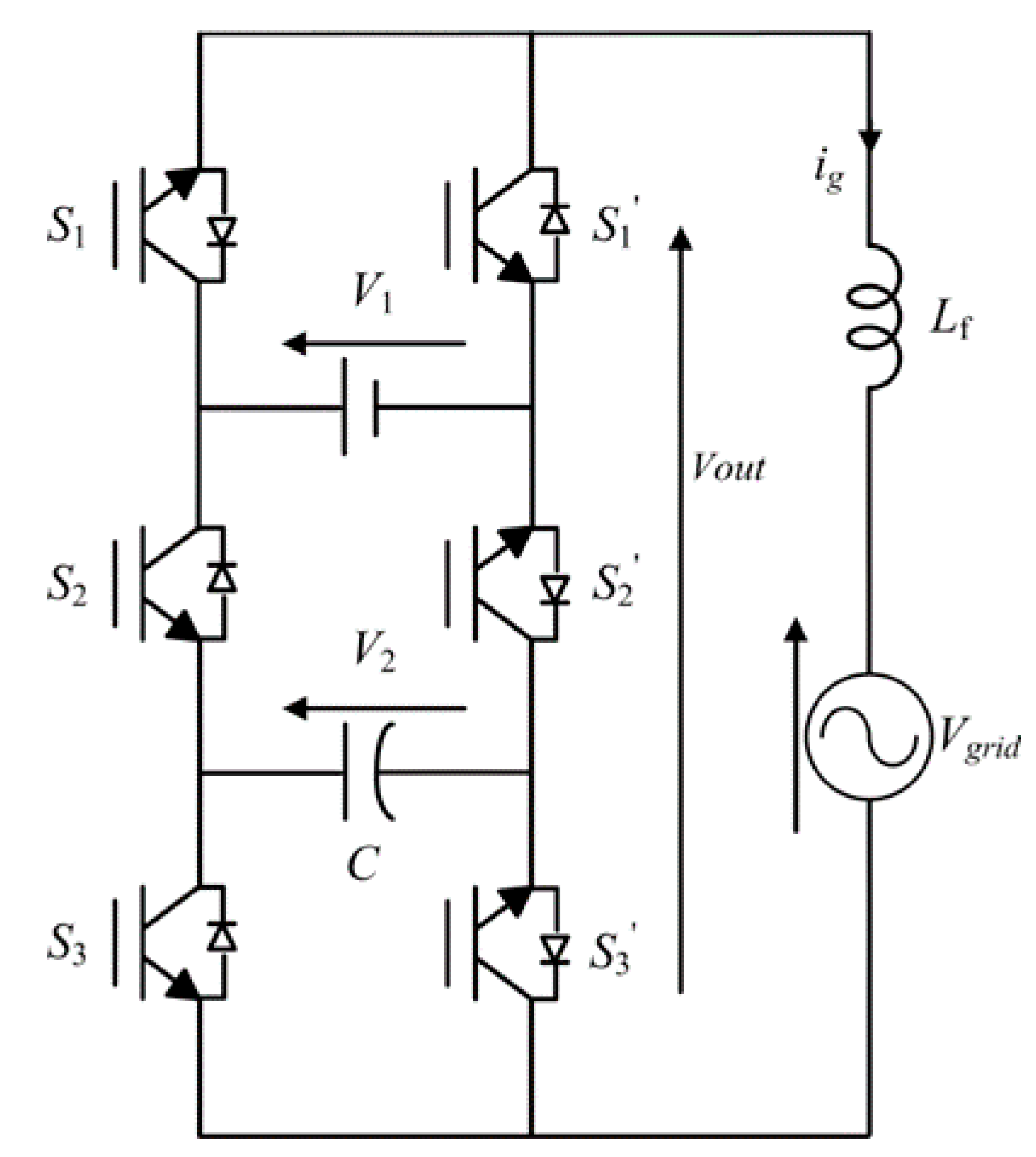
2.1. PUC7 Topology and Modelling

The PUC7 topology was initially proposed in [35]. Higher power quality can be achieved while employing a smaller number of active and passive components compared to other MLI topologies, which reduces the cost, volume, and the switching losses. The PUC7 topology is composed of six switches, one DC source, and one capacitor (Figure 1). If the capacitor voltage is controlled at 1/3 of the DC link voltage, seven voltage levels could be generated at the output terminals according to eight different switching states [18] (Table 1). It is worth noting that the switches S1, S2, and S3 are operating in a complementary manner with S1’, S2’, and S3 [10,35].
Let si ϵ {0,1} (i = 1,2,3) illustrate the control actions expressed by
s i = { 1 ,   if      S i   is   O N 0 ,   if      S i   is   O F F
Using the Kirchhoff’s laws, the mathematical model is obtained as follows:
C d V 2 ( t ) d t = ( s 3 s 2 ) i g ( t )
L f d i g ( t ) d t = ( s 1 s 2 ) V 1 ( t ) + ( s 2 s 3 ) V 2 ( t ) V g r i d ( t )
where
  • C: cell capacitors,
  • Lf: filtering inductor,
  • V1: DC source voltage,
  • V2: capacitor voltage,
  • Vgrid: grid voltage,
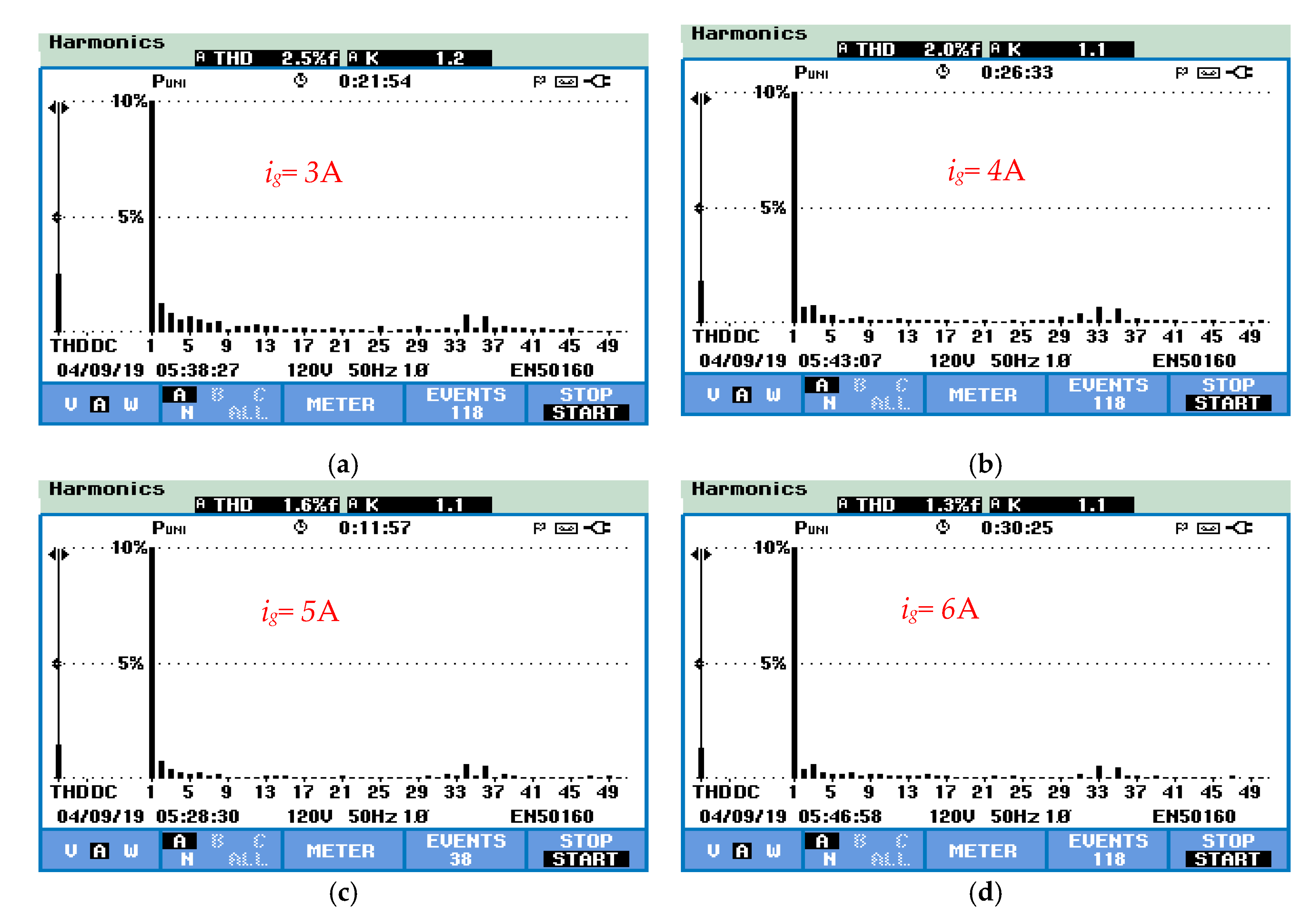
  • ig: injected grid current, and
  • s1, s2, s3: switching states.
The capacitor voltage V2 and the injected grid current ig are the variables to be controlled in order to guarantee a stable operation of the PUC7 inverter [18].

2.2. FCS-MPC for PUC7 Inverter

The application of FCS-MPC for power converters has gained extensive attention in the research society [14,15,18,19,22]. Indeed, it is a powerful control technique that can handle system nonlinearities and easily operate in multivariable case [14,24]. FCS-MPC considers the discrete characteristic of the power converter in order to design a discrete-time model that can be used to predict the behavior of the power converter, which allows applying the most suitable control vector in each sampling period [17]. In this work, the dynamics of the variables shown in Equations (2) and (3) are approximated during a sampling time Ts by
x ( k + 1 ) = x ( k ) + d x ( t ) d t · T s
Hence, the discrete-time model that allows the prediction of the controlled variables at the next (k + 1) step is obtained by
V 2 ( k + 1 ) = V 2 ( k ) + T s C ( s 3 s 2 ) i g ( k )
i g ( k + 1 ) = i g ( k ) + T s L f [ ( s 1 s 2 ) V 1 ( k ) + ( s 2 s 3 ) V 2 ( k ) V g r i d ( k )
Moreover, in order to ensure high tracking capabilities, the errors on the capacitor voltage and the injected grid current are divided by the maximum variations ΔV2max and Δigmax, respectively (variable normalization) [18]. The designed cost function is computed for the eight switching states, and the pattern that minimizes the cost function it is used at the next sampling time as illustrated in Figure 2. The proposed cost function is defined as follows:
c f = | i g i g ( k + 1 ) Δ i g max | + λ | V 2 V 2 ( k + 1 ) Δ V 2 max |
where
Δ V 2 max = 2 i g C T s
Δ i g max = 2 V 1 L f T s
It is worth noting that the weighting factor λ has a crucial effect in the design of the FCS-MPC as it ensures proper balancing among the variable tracking. The adjustment of the weighting factor can reduce the computing time and response delay, which can lead to better results. The nonlinear behavior of the studied system makes the selection of a fixed weighting factor more challenging, especially under variable conditions and under different constraints. Thus, autotuning of the weighting factor is an important task in designing the MPC scheme, as will be discussed in the next section.

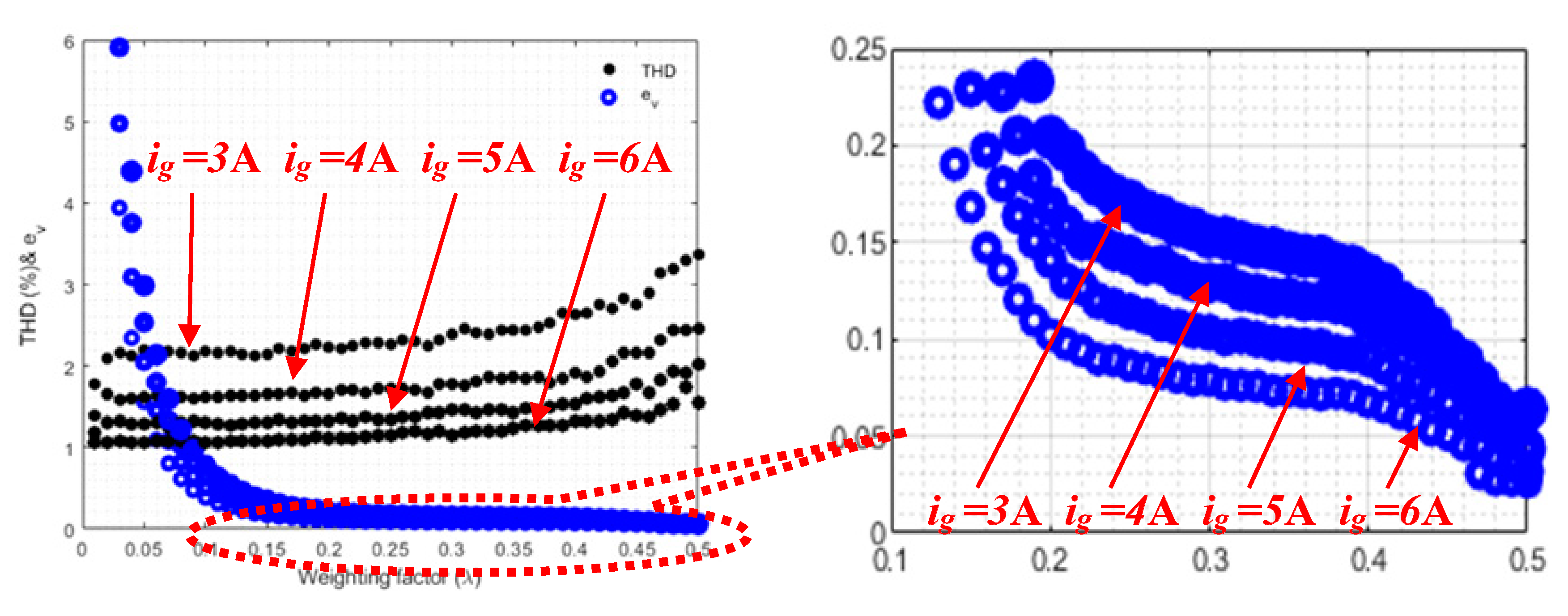
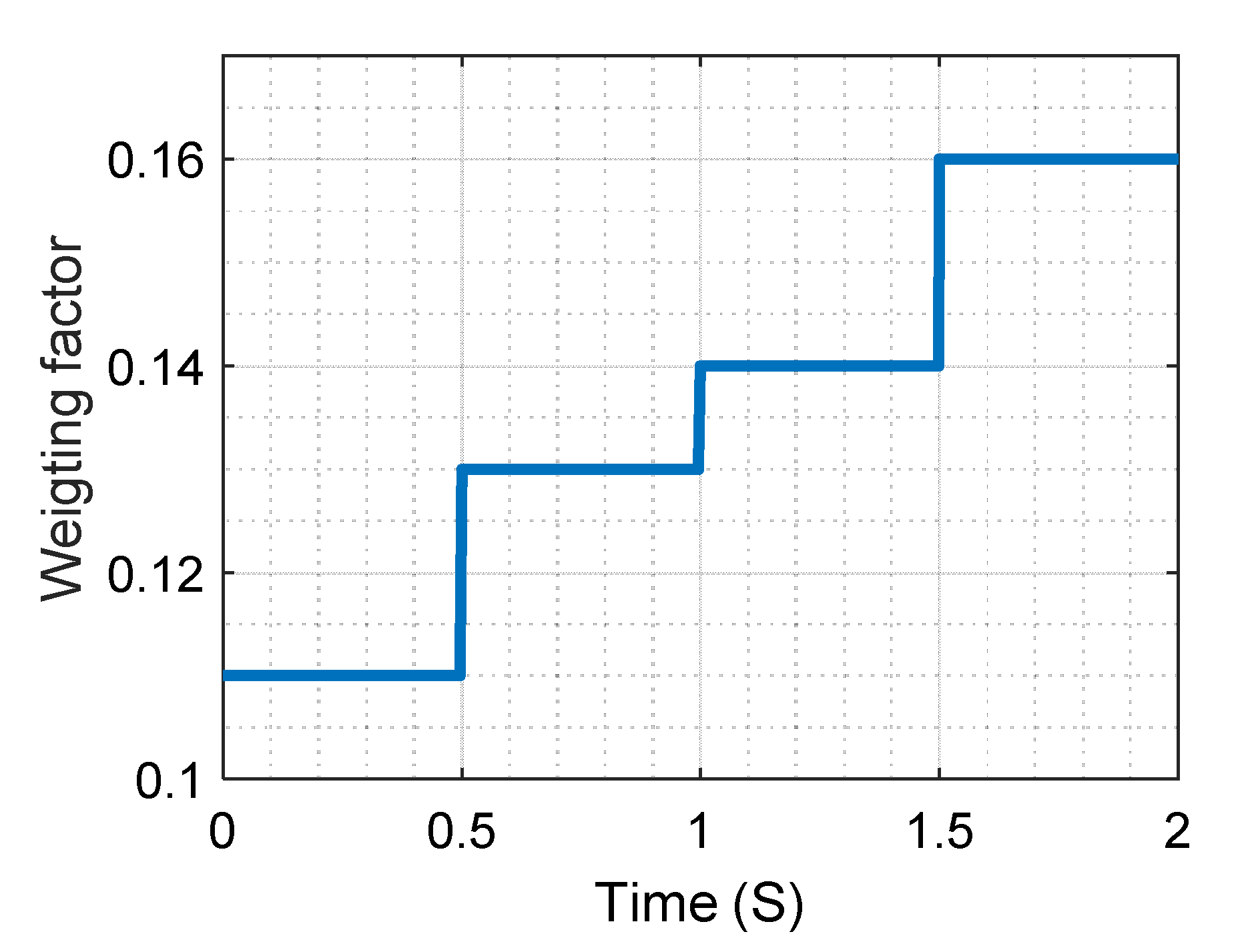
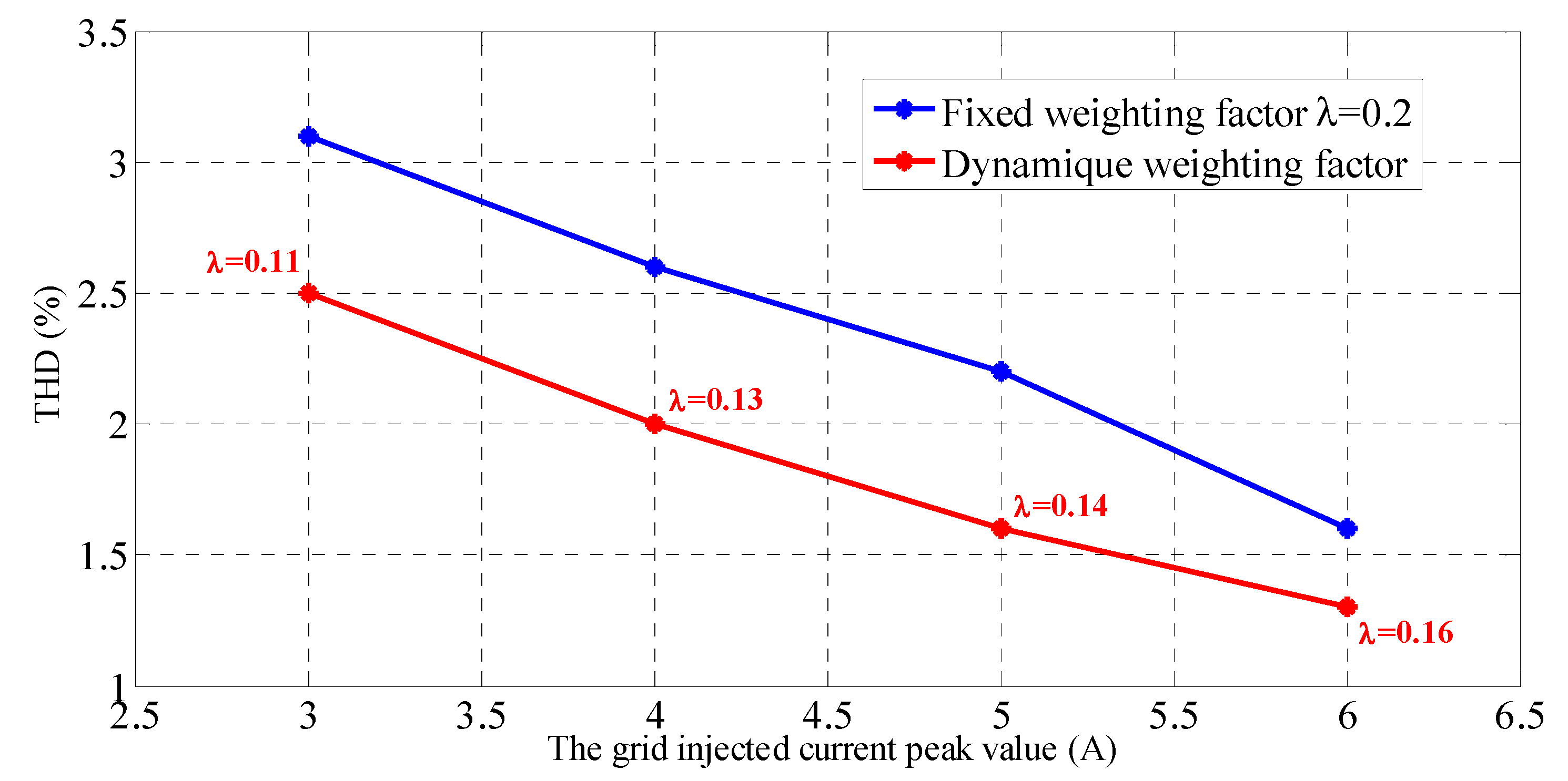
3. Autotuning of the Weighting Factor

ANN was used in this study for online autotuning to solve the challenge of optimal selection of weighting factor in the FCS-MPC algorithm. The approach allows the best value of the weighting factor to be chosen for each current rate, leading to good tracking quality system robustness to parameter variation [36].
The first step was to build a simulation model of the FCS-MPC for grid-connected PUC7 inverter in the MATLAB/Simulink (2018b, MathWorks, Natick, Massachusetts, USA) environment and then test the system under different operating conditions to check its performance. After that, a MATLAB algorithm was coded to enable collection of data from various tests (different operating conditions). In the current case study, the simulation was run with a set of weighting factors (from 0.001 to 0.5 at a 0.001 step size), while the injected grid current was changed from 3 to 6 A. The THD of the grid current ( T H D i g ) and the mean absolute error voltage regulation loop ( e v ) were recorded in each simulation scenario.
The next step was to use the collected data to train the ANN to be able to predict inverter behavior for any current rate at different values of the weighting factor. Bayesian regularized algorithm was selected to train the network due to its robustness. The algorithm is based on a mathematical process that transforms a nonlinear regression into a statistical problem, which does not need lengthy cross-validation. It is able to reduce the mean squared errors and build an accurate model [37]. The advantage of Bayesian regularized ANN is that the models are solid, and the validation process in standard regression methods, such as backpropagation steps, is unnecessary. The trained neural network was able to provide the possible T H D i g and ev for a given weighting factor and injected grid current. This work was focused on the minimization of these two performance criteria ( e v and T H D i g ) due to their high effect on the overall system performance.
The authors in [29] proposed a similar solution with a focus on the minimization of the average switching frequency in addition to the enhancement of the quality of injected grid current of a two-level inverter. However, the regulation of the DC link voltage in the standard three-phase two-level inverter is much less complex compared to the PUC topology, which was the focus of this study. Moreover, another algorithm was developed in this study to select the most appropriate weighting factor at each sampling time using the outputs of the ANN and the function given in Equation (10). The proposed approach provides better accuracy and robustness because it considers the injected grid current as input during the training of ANN, which is different to that proposed in [29].
f a = α × T H D i g + ( 1 α ) e v
The function fa allows a proper balance between the THDig and e v , which facilitates optimization of the control process based on the system requirements. In the studied system, the T H D i g minimization was the most significant criteria to optimize in order to meet international standards (e.g., IEEE 519-1992). Therefore, when tuning the weighting factor, a high priority was given to the T H D i g (90%), and less priority was given to the capacitor voltage regulation. In the last stage, the devolved neural network was implemented to predict the next inverter state while providing the required information in order to determine the optimal weighting factor. The weighting factor that would reduce the function given by Equation (10) was selected ( e v and T H D i g ) were within acceptable ranges). The obtained value of α, which fit the lowest value of function fa, was selected and substituted in the cost function. The different steps of the proposed autotuning weighting factor process are summarized in Figure 3.

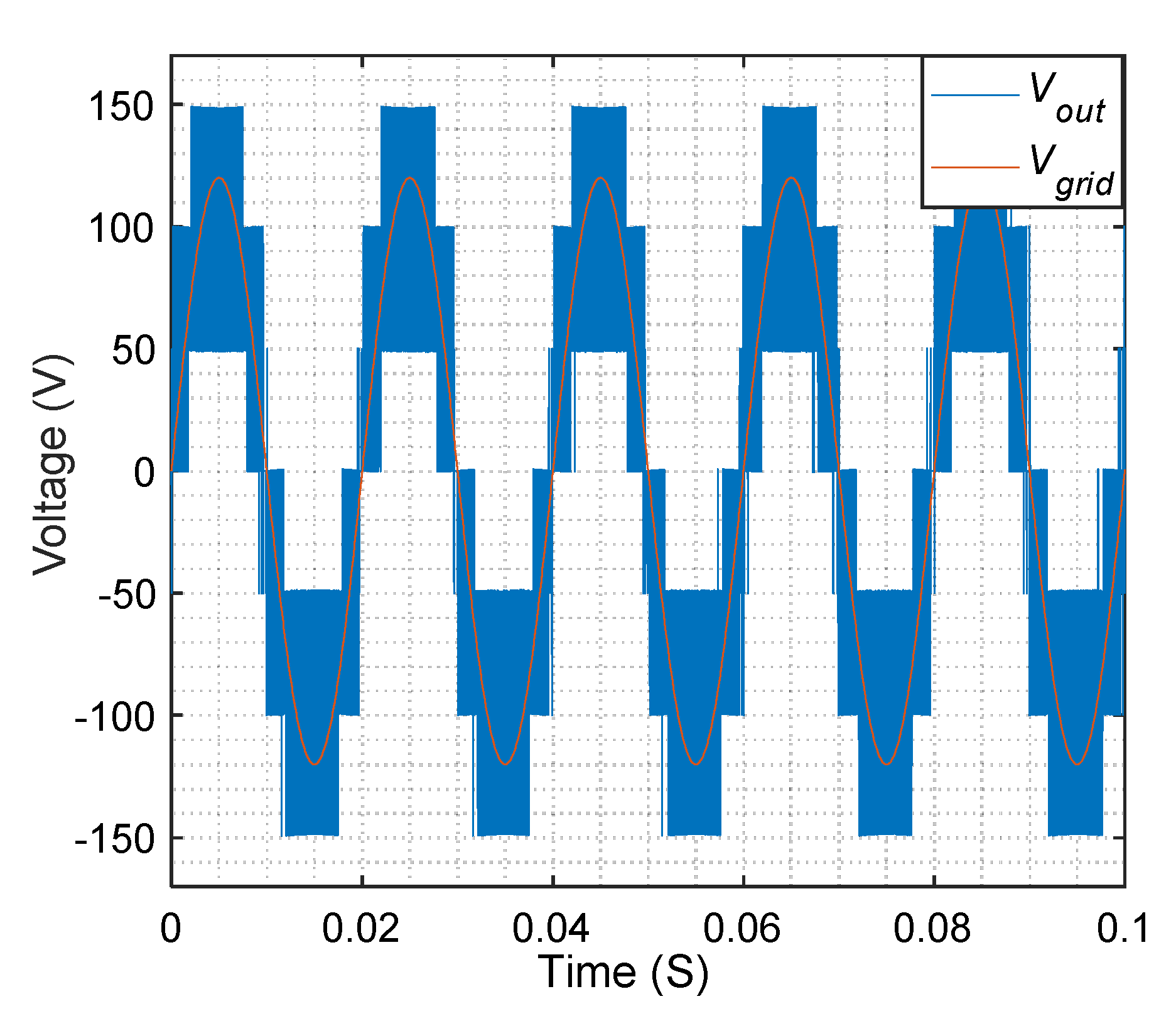
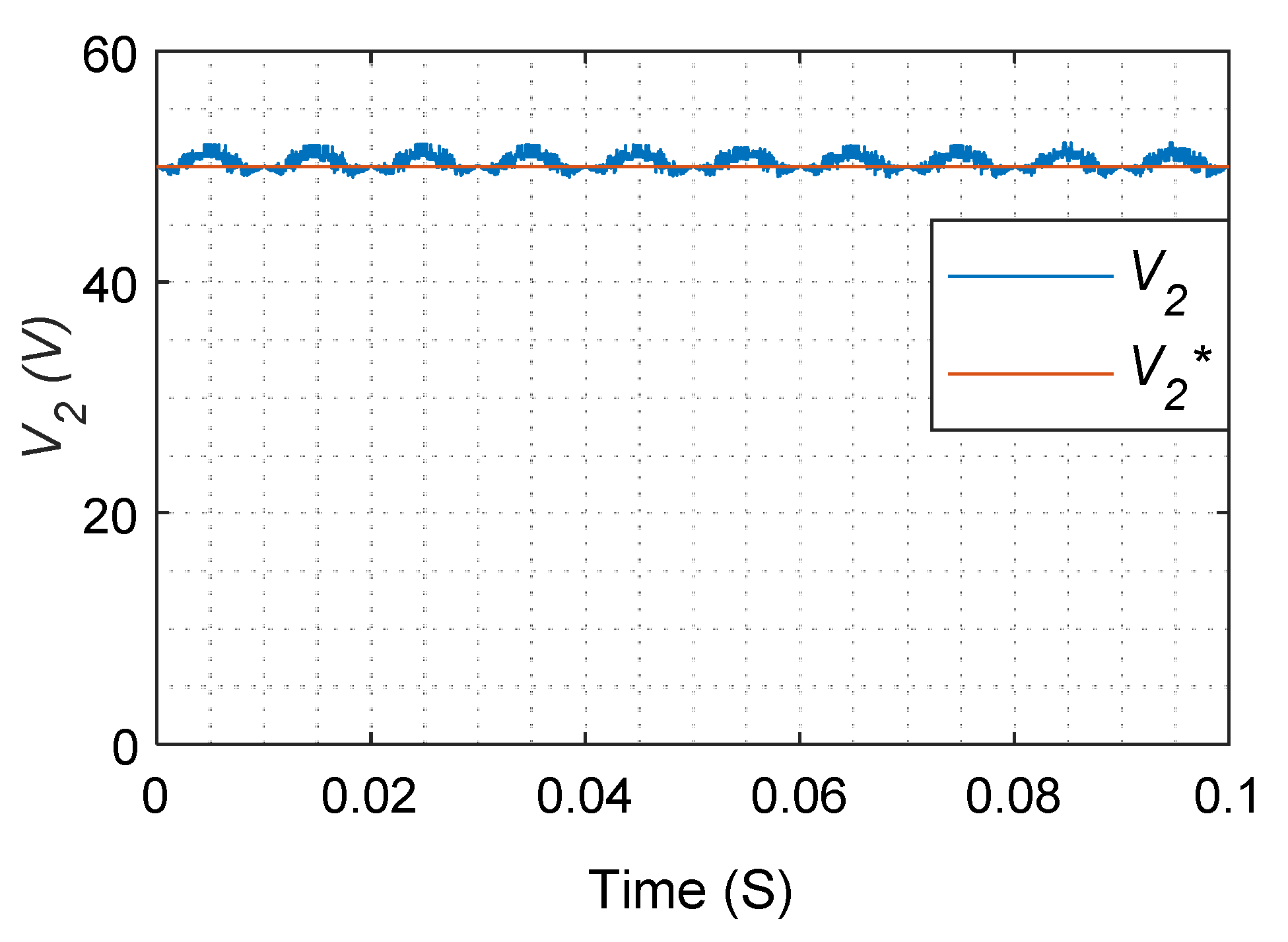
4. Simulation Results

A comprehensive simulation study was conducted using the parameters listed in Table 2. The performance of the grid-tied PUC7 inverter with FCS-MPC was evaluated under different operating conditions. An algorithm was established to run the system with different injected grid current with peak values of 3, 4, 5, and 6 A, along with different weighting factor values (0 to 0.5 at 0.01 step size). The obtained T H D i g as well as the mean absolute error e v value between the desired voltage and the measured voltage across the capacitor versus the variation of the weighting factor are shown simultaneously in Figure 4.
For different grid current values, it can be clearly seen from Figure 4 that the T H D i g was small for low values of the weighting factor and vice versa. In contrast, the absolute error of the capacitor voltage e v showed high values for low values of weighting factor, then decreased when the weighting factor was increased. The collected data were used to train the used ANN in order to emulate the behavior of the whole system and to select the most appropriate weighting factor in each operating condition.
The current study was mainly focused on the minimization of the T H D i g , which is the most significant power quality criteria.
Figure 5 presents the T H D i g variation at the fixed weighting factor selected in [18] and the proposed ANN-based dynamic weighting factor. It is obvious that the proposed weighting factor provided better THD variation in all the presented ranges of injected grid current. It should be mentioned that the peaks, which occurred during the transition periods of current change, were due to the fact that the calculation of the THD was affected by the numerical process calculation; however, physically, there was no such effect, as can be clearly seen during the dynamic transient of the injected grid current in Figure 6. Furthermore, it can be said that there was an important improvement in the quality of the injected grid current when the proposed algorithm was used. In addition, it is evident that the T H D i g in different current values met the international standard requirements (IEEE 519–1992).
Figure 6 shows the obtained injected grid current and its reference. The zoom taken within this figure highlights the good quality of the injected current for different values of the current. It can be noticed that pursuing of the reference current was ensured in a smooth manner during the dynamic transients. Figure 7 shows the weighting factor evolution under different current values. Figure 8 shows the output voltage of the inverter along with the grid voltage.
Figure 9 presents the voltage across the capacitor, where the capacitor voltage was maintained at its reference value, which was 50 V. The minor ripples in this voltage did not have any impact on the dynamic behavior of the inverter, which demonstrates the validity and efficacy of the proposed control technique.

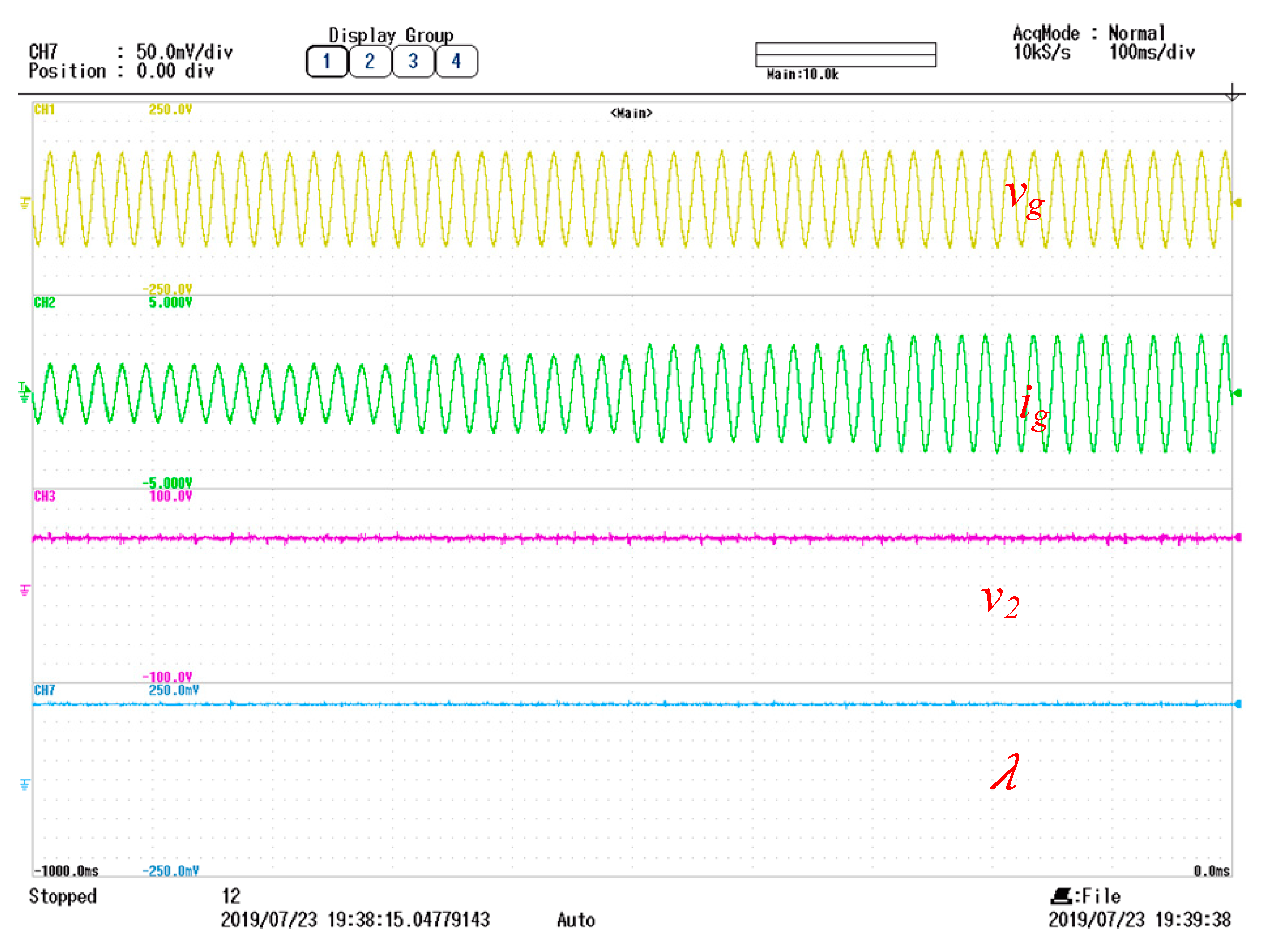
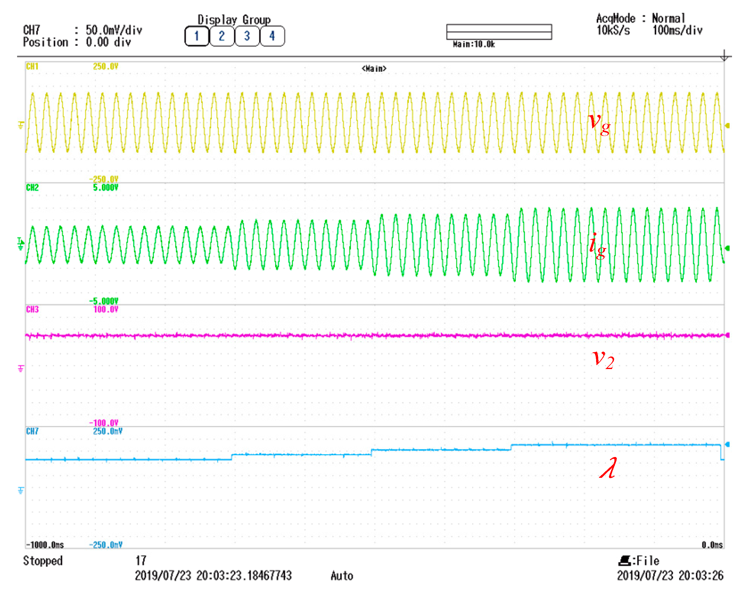
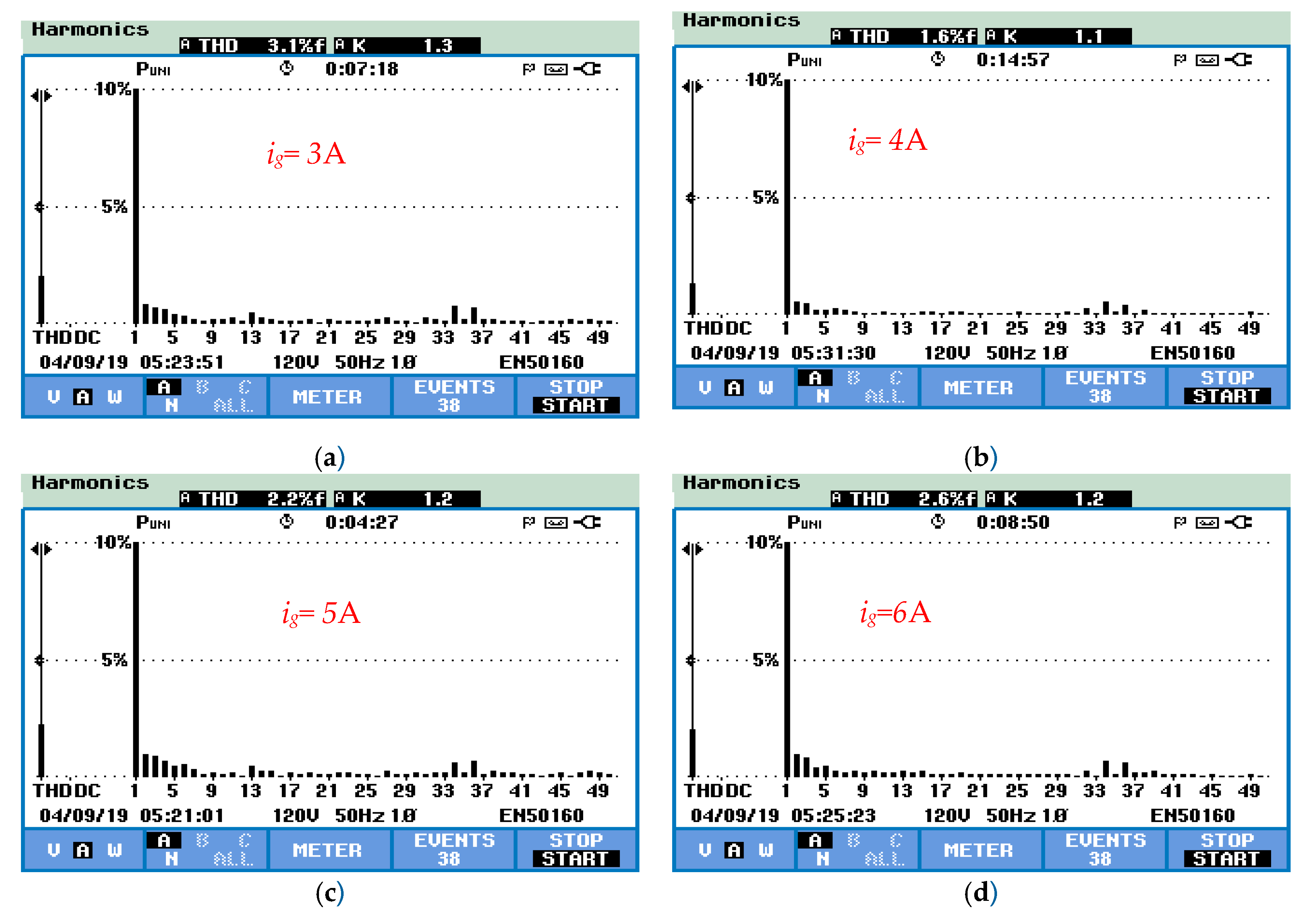
5. Experimental Results

The experimental performance validation was performed on a grid-tied PUC7 inverter using a dSPACE control platform (dS1103, dSPACE GmbH, Paderborn, Germany) (Figure 10). The experimental system parameters are listed in Table 2. The FLUKE 435 Series II power quality and energy analyzer was used for the THD measurement.
The experimental tests were conducted under the same simulation operating conditions. Figure 11 and Figure 12 represent the experimental results showing the grid injected current at fixed weighting factor (equal to 0.2) and dynamic weighting factor, respectively. It can be seen that the weighting factor was adjusted dynamically according to the current variation, i.e., 0.11, 0.13, 0.14, and 0.16, for the peak values of 3, 4, 5, and 6 A, respectively. The voltage across the capacitor perfectly tracked the reference value of 50 V in both cases (constant and dynamic). On the other side, the injected grid current adequately tracked its sinusoidal reference. In order to identify the best tuning scenario (fixed or dynamic weighting factor), the THD of the injected grid current was measured at different current ranges using the power analyzer. The measured THDs for both weighting factor cases are presented in Figure 13 and Figure 14. Figure 15 shows a comparison between the measured THD values at dynamic weighting factors (in red) and fixed weighting factor (in blue). From this figure, it is worth noting that the proposed dynamic tuning algorithm showed a clear superiority in minimizing the grid current THD compared to the fixed tuning technique. Figure 16 shows the grid voltage, the injected grid current, the voltage across the capacitor, and the output voltage of the studied single-phase seven-level PUC inverter. The presented results were measured under a current peak value of 6 A, and the tuned weighting factor value was obtained using the dynamic weighting factor algorithm. It can be seen that the injected grid current followed its sinusoidal reference with high power quality. The voltage across the capacitor was well controlled around the reference value of 50 V with very low ripples, and the output voltage showed the expected seven levels.

6. Conclusions

In this paper, a real-time ANN-based weighting factor autotuning algorithm is proposed for the design of FCS-MPC of a grid-connected PUC7 inverter. The proposed solution shows high capability in selecting the most appropriate weighting factor for different grid current values while balancing the capacitor voltage around the desired value with low voltage ripples. The presented simulation and experimental results have shown that the proposed algorithm leads to a higher power quality compared to the standard FCS-MPC due to its higher capability in minimizing the grid current THD at different current ratings.

Author Contributions

This paper is a result of the full collaboration of all the authors. Conceptualization, M.M.S. and A.K.; Methodology, M.M.S., A.K., S.S.R.; Simulation, M.M.S., A.K., M.T.; Experimental, A.K.; investigation and validation, H.A.R.; Writing-Original Draft Preparation, M.M.S. and A.K.; Writing-Review & Editing, S.S.R., M.T., H.A.R. All authors have read and agreed to the published version of the manuscript.

Funding

This research was funded by NPRP 9-310-2-134 from the Qatar National Research Fund (QNRF is a member of Qatar Foundation). The statements made herein are solely the responsibility of the authors.

Acknowledgments

This publication was made possible by NPRP 9-310-2-134 from the Qatar National Research Fund (QNRF is a member of Qatar Foundation). The statements made herein are solely the responsibility of the authors.

Conflicts of Interest

The authors declare no conflict of interest.

References

  1. Rodríguez, J.; Lai, J.; Peng, F.Z. Multilevel inverters: A survey of topologies, controls, and applications. IEEE Trans. Ind. Electron. 2002, 49, 724–738. [Google Scholar] [CrossRef] [Green Version]
  2. Abu-Rub, H.; Malinowski, M.; Al-Haddad, K. Power Electronics for Renewable Energy Systems, Transportation and Industrial Applications; Wiley: Hoboken, NJ, USA, 2014. [Google Scholar]
  3. Babaei, E.; Alilu, S.; Laali, S.; Member, S. A new general topology for cascaded multilevel inverters with reduced number of components based on developed h-bridge. IEEE Trans. Ind. Electron. 2014, 61, 3932–3939. [Google Scholar] [CrossRef]
  4. Abu-Rub, H.; Holtz, J.; Rodriguez, J.; Baoming, G. Medium-voltage multilevel converters state of the art, challenges, and requirements in industrial applications. IEEE Trans. Ind. Electron. 2010, 57, 2581–2596. [Google Scholar] [CrossRef]
  5. Sun, D.; Ge, B.; Liang, W.; Abu-rub, H.; Member, S. An energy stored quasi-z-source cascade multilevel inverter-based photovoltaic. IEEE Trans. Ind. Electron. 2015, 62, 5458–5467. [Google Scholar] [CrossRef]
  6. Chavarria, J.; Biel, D.; Guinjoan, F.; Meza, C.; Negroni, J.J. Energy-balance control of PV cascaded multilevel grid-connected inverters under level-shifted and phase-shifted PWMs. IEEE Trans. Ind. Electron. 2013, 60, 98–111. [Google Scholar] [CrossRef]
  7. Babaei, E.; Laali, S.; Member, S.; Alilu, S. Cascaded multilevel inverter with series connection of novel h-bridge basic units. IEEE Trans. Ind. Electron. 2014, 61, 6664–6671. [Google Scholar] [CrossRef]
  8. Babaei, E.; Laali, S.; Member, S. Optimum structures of proposed new cascaded multilevel inverter with reduced number of components. IEEE Trans. Ind. Electron. 2015, 62, 6887–6895. [Google Scholar] [CrossRef]
  9. Sheir, A.; Orabi, M.; Ahmed, M.E.; Iqbal, A.; Youssef, M. A high efficiency single-phase multilevel packed u cell inverter for photovoltaic applications. In Proceedings of the 2014 IEEE 36th International Telecommunications Energy Conference (INTELEC), Vancouver, BC, Canada, 28 September–2 October 2014; pp. 1–6. [Google Scholar] [CrossRef]
  10. Ounejjar, Y.; Al-haddad, K.; Grégoire, L. Packed u cells multilevel converter topology: Theoretical study and experimental validation. IEEE Trans. Ind. Electron. 2011, 58, 1294–1306. [Google Scholar] [CrossRef]
  11. Trabelsi, M.; Ghazi, K.A.; Al-Emadi, N.; Ben-Brahim, L. A weighted real-time predictive controller for a grid connected flying capacitors inverter. Int. J. Electr. Power Energy Syst. 2013, 49, 322–332. [Google Scholar] [CrossRef]
  12. Vahedi, H.; Trabelsi, M. Single-DC-Source Multilevel Inverters; Springer Nature: Basel, Switzerland, 2019. [Google Scholar]
  13. Krama, A.; Zellouma, L.; Rabhi, B.; Refaat, S.S.; Bouzidi, M. Real-Time Implementation of High Performance Control Scheme for Grid-Tied PV System for Power Quality Enhancement Based on MPPC-SVM Optimized by PSO Algorithm. Energies 2018, 11, 3516. [Google Scholar] [CrossRef] [Green Version]
  14. Rodriguez, J.; Kazmierkowski, M.P.; Espinoza, J.R.; Zanchetta, P.; Abu-Rub, H. State of the art of finite control set model predictive control in power electronics. IEEE Trans. Ind. Inform. 2013, 9, 1003–1016. [Google Scholar] [CrossRef]
  15. Guzinski, J.; Abu-rub, H. Speed sensorless induction motor drive with predictive current controller. IEEE Trans. Ind. Electron. 2013, 60, 699–709. [Google Scholar] [CrossRef]
  16. Aurtenechea, S.; Rodríguez, M.A.; Oyarbide, E.; Torrealday, J.R. Predictive control strategy for DC/AC converters based on direct power control. IEEE Trans. Ind. Electron. 2007, 54, 1261–1271. [Google Scholar] [CrossRef]
  17. Rodrıguez, J.; Abu-Rub, H.; Perez, M.A.; Kouro, S. Application of predictive control. In Power Electronics and Drives; Springer: Berlin/Heidelberg, Germany, 2014. [Google Scholar]
  18. Trabelsi, M.; Bayhan, S.; Ghazi, K.A.; Haitham, A.-R.; Lazhar, B.-B. Finite-control-set model predictive control for grid-connected packed-u-cells multilevel inverter. IEEE Trans. Ind. Electron. 2016, 63, 7286–7295. [Google Scholar] [CrossRef]
  19. Cortés, P.; Kazmierkowski, M.P.; Kennel, R.M.; Quevedo, D.E.; Rodriguez, J. Predictive control in power electronics and drives. IEEE Trans. Ind. Electron. 2008, 55, 4312–4324. [Google Scholar] [CrossRef]
  20. Kouro, S.; Cortes, P.; Vargas, R.; Ammann, U.; Rodriguez, J. Model predictive control-a simple and powerful method to control power converters. IEEE Trans. Ind. Electron. 2009, 56, 1826–1838. [Google Scholar] [CrossRef]
  21. Abdelbasset, K.; Refaat, S.S.; Trabelsi, M. Model Predictive Control for a 9-Level Packed U-Cells based Grid-Connected PV System. In Proceedings of the IEEE conference in smart grid and renewable energy, Doha, Qatar, 19–21 November 2019. [Google Scholar] [CrossRef]
  22. Cortés, P.; Kouro, S.; La Rocca, B.; Vargas, R.; Rodriguez, J.; Leon, J.I.; Vazquez, S.; Franquelo, L.G. Guidelines for weighting factors design in model predictive control of power converters and drives. In Proceedings of the IEEE International Conference on Industrial Technology, Gippsland, VIC, Australia, 10–13 February 2009. [Google Scholar] [CrossRef]
  23. Liu, W.; Wang, G. Auto-tuning procedure for model-based predictive controlle. In Proceedings of the IEEE International Conference on Systems, Man and Cybernetics, Cybernetics Evolving to Systems, Humans, Organizations, and Their Complex Interactions, Nashville, TN, USA, 8–11 October 2000. [Google Scholar]
  24. Shadmand, M.B.; Jain, S.; Balog, R.S. Auto-tuning technique for the cost function weight factors in model predictive control for power electronics interface. IEEE J. Emerg. Sel. Top. Power Electron. 2018, 7, 1408–1420. [Google Scholar] [CrossRef]
  25. Davari, S.A.; Khaburi, D.A.; Kennel, R.; Member, S. An improved FCS-MPC algorithm for an induction motor with an imposed optimized weighting factor. IEEE Trans. Power Electron. 2012, 27, 1540–1551. [Google Scholar] [CrossRef]
  26. Razmjooy, N.; Khalilpour, M.; Ramezani, M. A new meta-heuristic optimization algorithm inspired by FIFA world cup competitions: Theory and its application in PID designing for AVR system. J. Control. Autom. Electr. Syst. 2016, 27, 419–440. [Google Scholar] [CrossRef]
  27. Liu, D.; Zhou, J.; Zhao, Y. Online tuning of weighting factors based on sugeno fuzzy method in predictive torque control of four-switch three-phase inverter-fed IM. In Proceedings of the 2016 International Symposium on Power Electronics, Electrical Drives, Automation and Motion (SPEEDAM), Anacapri, Italy, 22–24 June 2016. [Google Scholar]
  28. Kampisios, K.; Zanchetta, P.; Gerada, C.; Trentin, A.; Jasim, O. Induction motor parameters identification using genetic algorithms for varying flux levels. In Proceedings of the 13th International Power Electronics and Motion Control Conference, Poznan, Poland, 1–3 September 2008; pp. 887–892. [Google Scholar] [CrossRef]
  29. Dragicevic, T.; Novak, M. Weighting factor design in model predictive control of power electronic converters: An artificial neural network approach. IEEE Trans. Ind. Electron. 2018. [Google Scholar] [CrossRef] [Green Version]
  30. Gutiérrez-Urquídez, R.C.; Valencia-Palomo, G.; Rodríguez-Elias, O.M.; Trujillo, L. Systematic selection of tuning parameters for efficient predictive controllers using a multiobjective evolutionary algorithm. Appl. Soft Comput. J. 2015, 31, 326–338. [Google Scholar] [CrossRef]
  31. Zanchetta, P. Heuristic multi-objective optimization for cost function weights selection in finite states model predictive control. In Proceedings of the PRECEDE 2011-Workshop on Predictive Control. of Electrical Drives and Power Electronics, Munich, Germany, 14–15 October 2011; pp. 70–75. [Google Scholar] [CrossRef]
  32. Mc, P.; Negenborn, R.R.; De Schutter, B.; Lightbody, G. Weight optimisation for iterative distributed model predictive control applied to power networks. Eng. Appl. Artif. Intell. 2013, 26, 532–543. [Google Scholar] [CrossRef]
  33. Martínez, M.; Senent, J.S.; Blasco, X. Generalized predictive control using genetic algorithms (GAGPC). Eng. Appl. Artif. Intell. 2002, 11, 355–367. [Google Scholar] [CrossRef]
  34. Guazzelli, P.R.U.; Pereira, W.C.A.; Oliveira, C.M.R.; Castro, A.G.; Aguiar, M.L. Weighting factors optimization of predictive torque control of induction motor by multi-objective genetic algorithm. IEEE Trans. Power Electron. 2018, 34, 6628–6638. [Google Scholar] [CrossRef]
  35. Al-Haddad, K.; Ounejjar, Y.; Gregoire, L. Multilevel Electric Power Converter. US Patent US9331599B2, 17 November 2011. [Google Scholar]
  36. Kanaesalingam, S.R.K.; Ramachandaramurthy, V.K. Inteligent driven power quality monitoring using pseudomeasurement technique. In Proceedings of the 2009 10th International Conference on Electrical Power Quality and Utilisation, EPQU’09, Lodz, Poland, 15–17 September 2009; pp. 1–6. [Google Scholar] [CrossRef]
  37. Wang, J.; Shao, W.; Song, Z. Bayesian regularized Gaussian mixture regression with application to soft sensor modeling for multi-mode industrial processes. In Proceedings of the 2018 IEEE 7th Data Driven Control and Learning Systems Conference (DDCLS), Enshi, China, 25–27 May 2018; pp. 463–468. [Google Scholar] [CrossRef]
Figure 1. Grid-connected packed U-cell (PUC) inverter.
Energies 13 03107 g001
Figure 2. Finite control set model predictive control (FCS-MPC) scheme for grid-connected packed U-cell (PUC) inverter with weighting factor autotuning.
Energies 13 03107 g002
Figure 3. General scheme describing the principle of autotuning using artificial neural network (ANN).
Energies 13 03107 g003
Figure 4. THD of the grid current (THDig) and the mean absolute error voltage regulation loop (ev) versus the weighting factor.
Energies 13 03107 g004
Figure 5. Total harmonic distortion of the injected grid current for fixed and variable weighting factor.
Energies 13 03107 g005
Figure 6. Injected grid current when varying the reference.
Energies 13 03107 g006
Figure 7. Dynamics of the weighting factor according to the reference current value.
Energies 13 03107 g007
Figure 8. Output voltage of the inverter and the grid voltage.
Energies 13 03107 g008
Figure 9. Voltage across the capacitor.
Energies 13 03107 g009
Figure 10. Experimental setup.
Energies 13 03107 g010
Figure 11. Experimental results at fixed weighting factor.
Energies 13 03107 g011
Figure 12. Experimental results under dynamic weighting factor.
Energies 13 03107 g012
Figure 13. The THDig at fixed weighting factor and for different current ranges (a): ig = 3A, (b): ig = 4A, (c): ig = 5A, (d): ig = 6A.
Energies 13 03107 g013
Figure 14. The THDig umder dynamic weighting factor and for different current ranges: (a) ig = 3A, (b) ig = 4A, (c): ig = 5A, (d): ig = 6A.
Energies 13 03107 g014
Figure 15. The THD of the injected grid current in case of dynamic and fixed weighting factors under different current peak values.
Energies 13 03107 g015
Figure 16. Seven-level PUC (PUC7) waveforms under dynamic weighting factor.
Energies 13 03107 g016
Table 1. Switching states.
StateVoutS1S2S3
10000
2V2001
3V2V1010
4V1011
5V1100
6V1V2101
7V2110
80111
Table 2. System parameters.
ParametersValues
Inductance of the filter L f 5 mH
Capacitor C100 μF
Frequency f50 Hz
Sampling frequency Fs50 KHz
DC source voltage V1150 V
Grid voltage Vgrid (peak)120 V

