Control of a Fault-Tolerant Photovoltaic Energy Converter in Island Operation

 ,
,  ,
,
Abstract
:1. Introduction
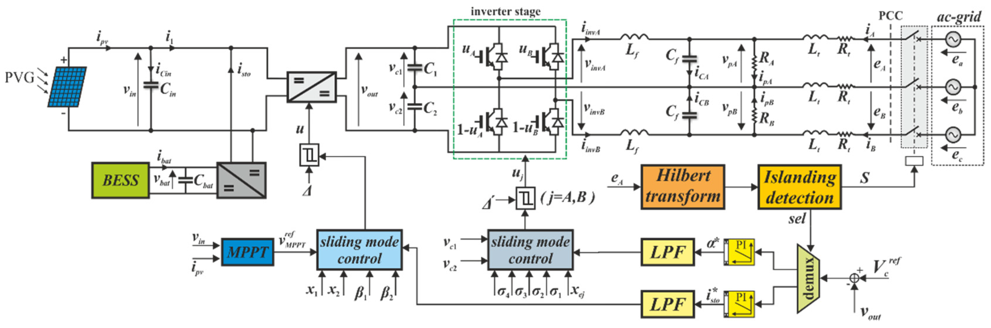
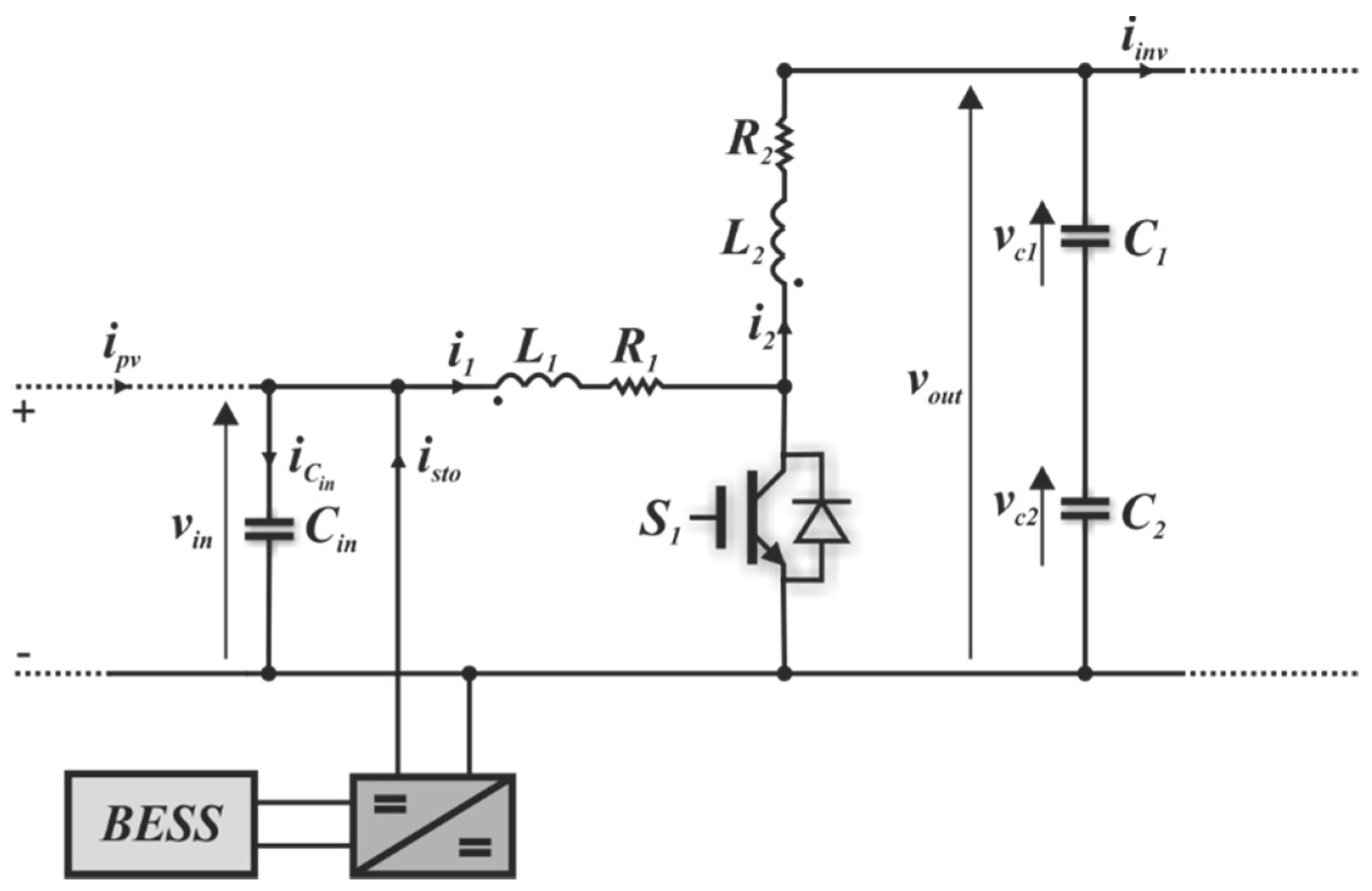
2. System Modeling
3. System Control
3.1. Normal Operation
3.2. Islanding Detection
3.3. Islanded Mode
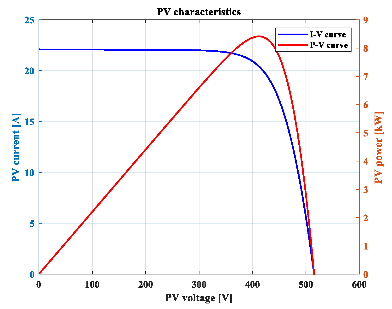
4. Numerical Results
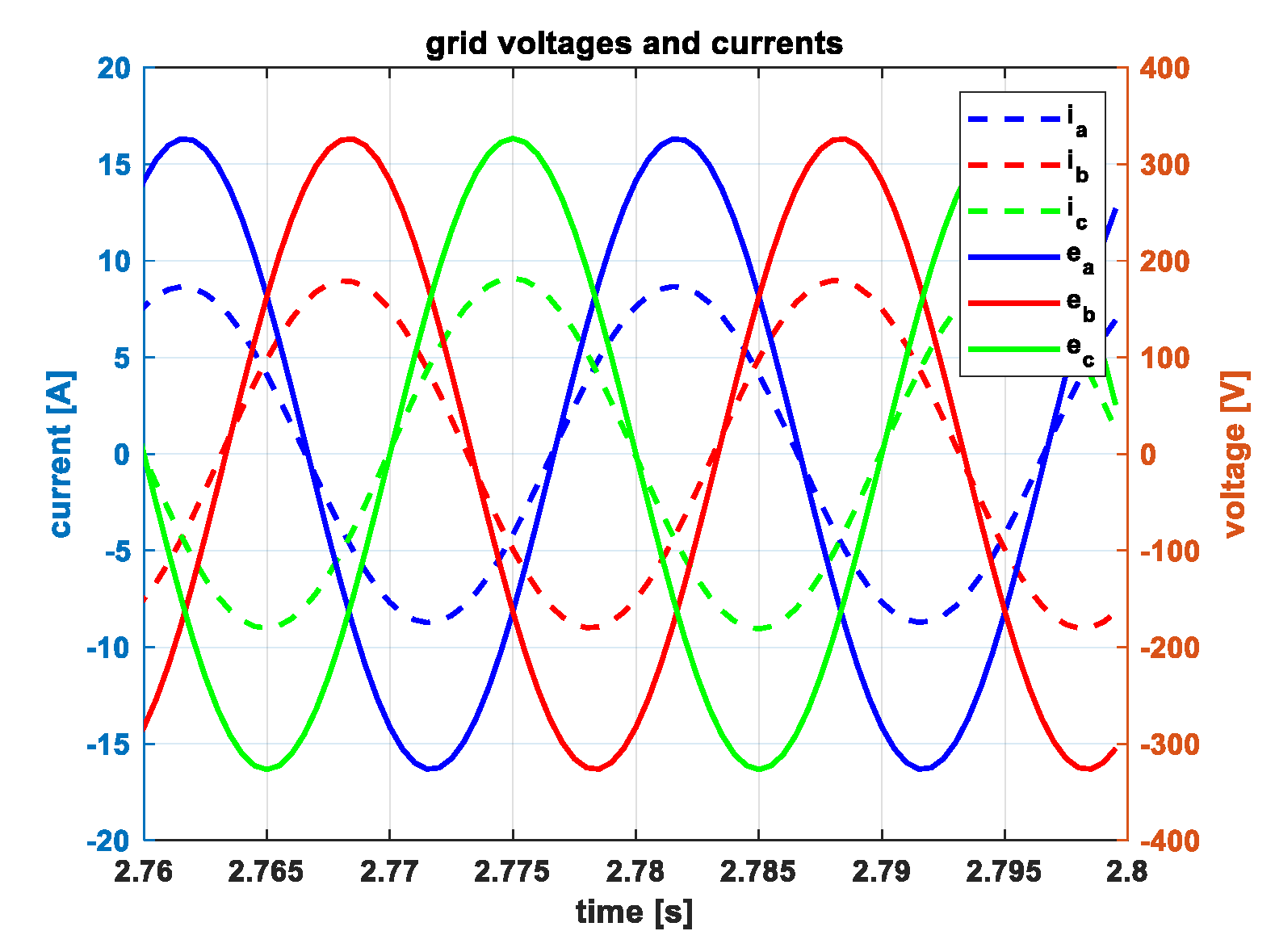
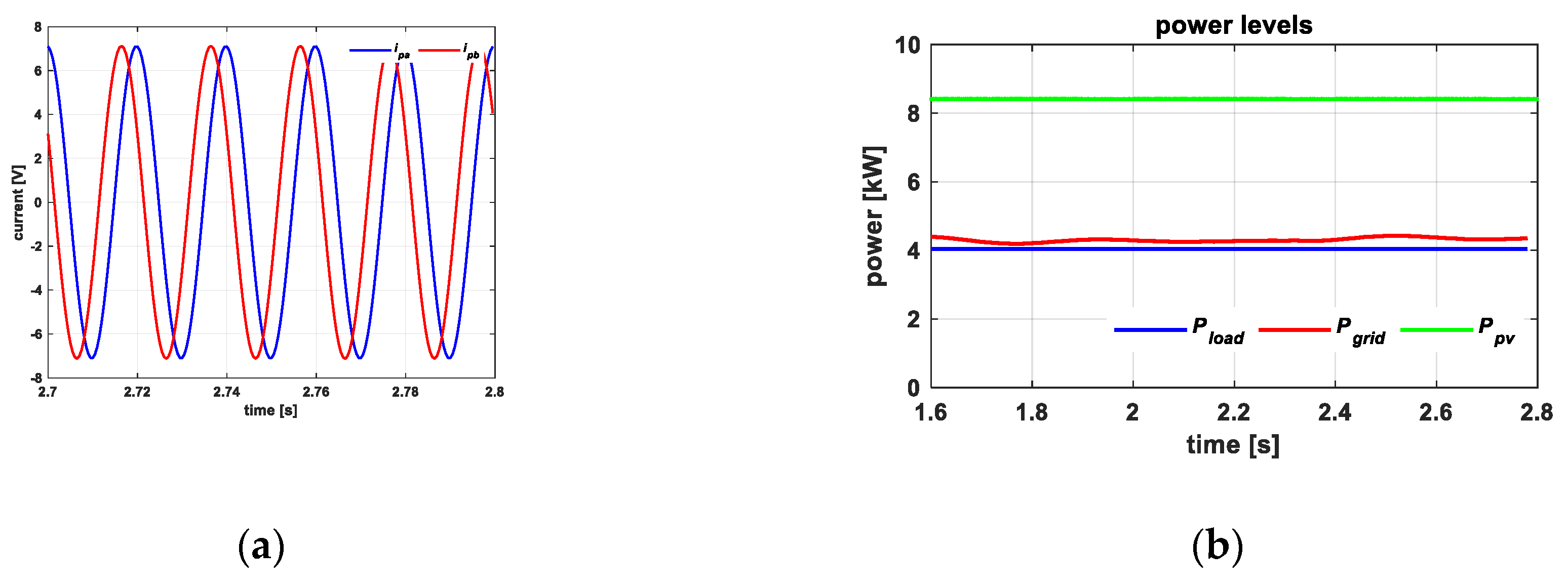
4.1. Normal Operation and Islanding Detection
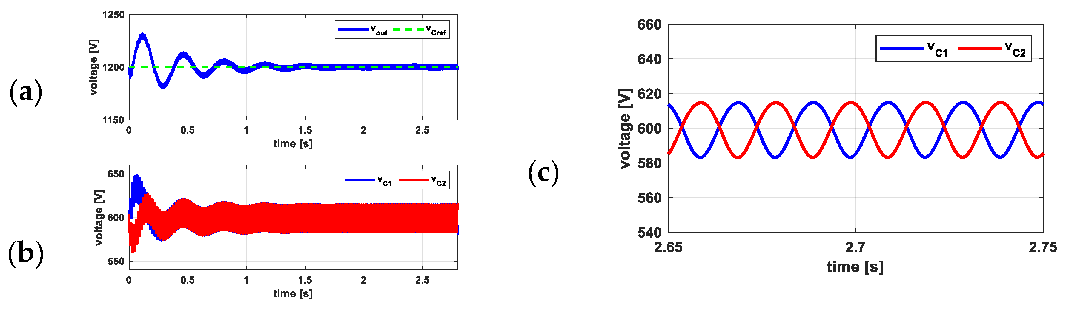
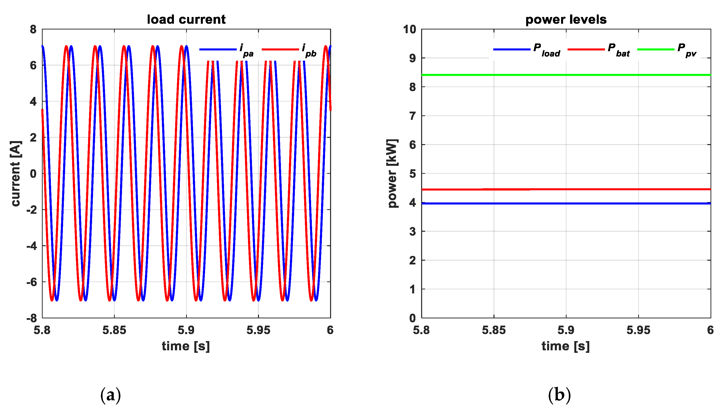
4.2. Islanded Mode
5. Conclusions
Author Contributions
Funding
Conflicts of Interest
Nomenclature
| C1; C2 | DC-link capacitors |
| Cbat | input capacitor of bidirectional DC-DC converter |
| Cin | input capacitor |
| E | rms line-to-line grid voltage |
| eA; eB | linetoline voltages |
| ibat | battery current |
| ipv | PV current |
| isto | storage current |
| iinvA; iinvB | inverter output currents |
| ipA; ipB | load currents |
| k | coupling coefficient |
| L | total inductance of coupled inductors |
| L0 | inductance of a single winding |
| L1; L2 | primary and a secondary inductor |
| Lf; Cf | inverter output filter |
| N1; N2 | turn number of the primary and secondary inductor |
| R1; R2 | resistors account for inductors copper losses |
| rn | winding ratio of the magnetically coupled inductors |
| RA; RB | load resistors |
| Rt; Lt | equivalent parameters of line three-phase transformer |
| S | circuit breaker activation signal |
| sel | demux selection signal |
| u | driving signal of coupled inductors DC-DC converter |
| uj | driving signal of inverter stage |
| vbat | battery voltage |
| vC1, vC2 | DClink voltages |
| vin | PV voltage |
| vinvA; vinvB | inverter output voltages |
| vpA; vpB | linetoline load voltages |
| vout | total DClink voltage |
| MPPT voltage reference | |
| α | angle between load voltages and network voltages |
| β1; β2 | coefficients of coupled inductors DC-DC converter sliding surface |
| x1; x2 | statevariables error of coupled inductors DC-DC converter sliding control |
| xej | vector of the statevariables error of inverter sliding control |
| Δ | half the amplitude of the hysteresis band in the sliding surface of coupled inductors DC-DC converter |
| Δ′ | half the amplitude of the hysteresis band in the sliding surface of inverter |
| σ1, σ2, σ3, σ4 | coefficients of inverter sliding surface |
| BESS | battery energy storage system |
| BMS | battery management system |
| DER | distributed energy resources |
| EPS | electric power systems |
| ID | islanding detection |
| IDM | islanding detection method |
| MPP | maximum power point |
| MPPT | maximum power point tracking |
| PCC | point of common coupling |
| P&O | perturb and observe |
| PV | photovoltaic |
| PVG | photovoltaic generator |
| RES | renewable energy sources |
| SOC | state of charge |
References
- Kouro, S.; Leon, J.I.; Vinnikov, D.; Franquelo, L.G. Grid-Connected Photovoltaic Systems: An Overview of Recent Research and Emerging PV Converter Technology. IEEE Ind. Electron. Mag. 2015, 9, 47–61. [Google Scholar] [CrossRef]
- Romero-Cadaval, E.; Spagnuolo, G.; Franquelo, L.G.; Ramos-Paja, C.A.; Suntio, T.; Xiao, W.M. Grid-Connected Photovoltaic Generation Plants: Components and Operation. IEEE Ind. Electron. Mag. 2013, 7, 6–20. [Google Scholar] [CrossRef] [Green Version]
- Romero-Cadaval, E.; Francois, B.; Malinowski, M.; Zhong, Q. Grid-Connected Photovoltaic Plants: An Alternative Energy Source, Replacing Conventional Sources. IEEE Ind. Electron. Mag. 2015, 9, 18–32. [Google Scholar] [CrossRef]
- European Technology & Innovation Platform. Available online: https://etip-pv.eu/ (accessed on 6 March 2020).
- Liserre, M.; Sauter, T.; Hung, J.Y. Future Energy Systems: Integrating Renewable Energy Sources into the Smart Power Grid through Industrial Electronics. IEEE Ind. Electron. Mag. 2010, 4, 18–37. [Google Scholar] [CrossRef]
- Petrone, G.; Spagnuolo, G.; Teodorescu, R.; Veerachary, M.; Vitelli, M. Reliability Issues in Photovoltaic Power Processing Systems. IEEE Trans. Ind. Electron. 2008, 55, 2569–2580. [Google Scholar] [CrossRef]
- Zeineldin, H.H.; El-Saadany, E.F.; Salama, M.M.A. Impact of DG interface control on islanding detection and nondetection zones. IEEE Trans. Power Deliv. 2006, 21, 1515–1523. [Google Scholar] [CrossRef]
- Yu, B.; Matsui, M.; Yu, G. A review of current anti-islanding methods for photovoltaic power system. Sol. Energy 2010, 84, 745–754. [Google Scholar] [CrossRef]
- Teodorescu, R.; Liserre, M.; Rodríguez, P. Grid Converters for Photovoltaic and Wind Power Systems; John Wiley & Sons Ltd.: Hoboken, NJ. USA, 2011. [Google Scholar]
- Kim, M.-S.; Haider, R.; Cho, G.-J.; Kim, C.-H.; Won, C.-Y.; Chai, J.-S. Comprehensive Review of Islanding Detection Methods for Distributed Generation Systems. Energies 2019, 12, 837. [Google Scholar] [CrossRef] [Green Version]
- Ku Ahmad, K.N.E.; Selvaraj, J.; Rahim, N.A. A review of the islanding detection methods in grid-connected PV inverters. Renew. Sustain. Energy Rev. 2013, 21, 756–766. [Google Scholar] [CrossRef]
- Reddy, V.R.; Sreeraj, E.S. A Feedback-Based Passive Islanding Detection Technique for One-Cycle-Controlled Single-Phase Inverter Used in Photovoltaic Systems. IEEE Trans. Ind. Electron. 2019, 67, 6541–6549. [Google Scholar] [CrossRef]
- Rostami, A.; Jalilian, A.; Zabihi, S.; Olamaei, J.; Pouresmaeil, E. Islanding Detection of Distributed Generation Based on Parallel Inductive Impedance Switching. IEEE Syst. J. 2020, 14, 813–823. [Google Scholar] [CrossRef] [Green Version]
- Bakhshi-Jafarabadi, R.; Sadeh, J.; Popov, M. Maximum Power Point Tracking Injection Method for Islanding Detection of Grid-Connected Photovoltaic Systems in Microgrid. IEEE Trans. Power Deliv. 2020. [Google Scholar] [CrossRef]
- Babak, S.; Mohamad Esmaeil, H.-G.; Iman, S. Comprehensive investigation of the voltage relay for anti-islanding protection of synchronous distributed generation. Int. Trans. Elect. Energy Syst. 2017, 27, 1–16. [Google Scholar]
- Abyaz, A.; Panahi, H.; Zamani, R.; Haes Alhelou, H.; Siano, P.; Shafie-khah, M.; Parente, M. An Effective Passive Islanding Detection Algorithm for Distributed Generations. Energies 2019, 12, 3160. [Google Scholar] [CrossRef] [Green Version]
- Haider, R.; Kim, C.H.; Ghanbari, T.; Bukhari, S.B.A.; Zaman, M.S.; Baloch, S.; Oh, Y.S. Passive islanding detection scheme based on autocorrelation function of modal current envelope for photovoltaic units. IET Gener. Transm. Distrib. 2018, 12, 726–736. [Google Scholar] [CrossRef]
- Sirico, C.; Teodorescu, R.; Séra, D.; Coppola, M.; Guerriero, P.; Iannuzzi, D.; Dannier, A. PV Module-Level CHB Inverter with Integrated Battery Energy Storage System. Energies 2019, 12, 4601. [Google Scholar] [CrossRef] [Green Version]
- Lauria, D.; Coppola, M. Design and control of an advanced PV inverter. Solar Energy 2014, 110, 533–542. [Google Scholar] [CrossRef]
- Coppola, M.; Lauria, D.; Napoli, E. On the design and the efficiency of coupled step-up dc-dc converters. In Proceedings of the IEEE International Conference on Electrical Systems for Aircraft, Railway and Ship Propulsion (ESARS), Bologna, Italy, 19–21 October 2010. [Google Scholar]
- Coppola, M.; Lauria, D.; Napoli, E. Optimal design and control of coupled-inductors step-up dc-dc converter. In Proceedings of the 2011 IEEE International Conference on Clean Electrical Power (ICCEP), Ischia, Italy, 14–16 June 2011; pp. 81–88. [Google Scholar]
- Guerriero, P.; Coppola, M.; Cennamo, P.; Daliento, S.; Lauria, D. A single panel PV microinverter based on coupled inductor DC-DC. In Proceedings of the 2017 IEEE International Conference on Environment and Electrical Engineering and 2017 IEEE Industrial and Commercial Power Systems Europe (EEEIC/I & CPS Europe), Milan, Italy, 6–9 June 2017; pp. 1–5. [Google Scholar]
- IEEE. 1547–2018-IEEE Standard for Interconnection and Interoperability of Distributed Energy Resources with Associated Electric Power Systems Interfaces; IEEE: Piscataway, NJ, USA, 2018. [Google Scholar]
- Dwari, S.; Jayawant, S.; Beechner, T.; Miller, S.K.; Mathew, A.; Min, C.; Riehl, J.; Sun, J. Dynamics Characterization of Coupled-Inductor Boost DC-DC Converters. In Proceedings of the 2006 IEEE Workshops on Computers in Power Electronics, Troy, NY, USA, 16–19 July 2006. [Google Scholar]
- Skvarenina, T.L. The Power Electronics Handbook; CRC Press: Boca Raton, FL, USA, 2002; Chapter 8. [Google Scholar]
- Mattavelli, P.; Rossetto, L.; Spiazzi, G. Small-signal analysis of DC-DC converters with sliding mode control. IEEE Trans. Power Electron. 1997, 12, 96–102. [Google Scholar] [CrossRef] [Green Version]
- IEEE. 1547.1–2005-IEEE Standard Conformance Test Procedures for Equipment Interconnecting Distributed Resources with Electric Power Systems, IEEE Std.; IEEE: Piscataway, NJ, USA, 2005; ISBN 0-7381-4736-2 SH95346. [Google Scholar]


| Parameters | Values |
|---|---|
| E (V) | 400 |
| Cin (mF) | 10 |
| L (mH) | 20 |
| R1 (mΩ) | 27.14 |
| R2 (mΩ) | 67.86 |
| Lf (mH) | 10 |
| Cf (mF) | 0.5 |
| Rt (mΩ) | 0.267 |
| Lt (mH) | 8.46 |
| Parameters | Values |
|---|---|
| Iph (A) | 7.362 |
| I0 (A) | 0.351 |
| a | 1.2 |
| Vt (V) | 0.025 |
| Rs (Ω) | 0.204 |
| Rsh (Ω) | 1168 |
| ns | 60 |
| Parameters | Values |
|---|---|
| TMPPT (ms) | 100 |
| ΔVMPPT (V) | 1 |
| (V) | 414.2 |
| β1 | 0.5 |
| β2 | −1 |
| Δ | 1 |
| σ1 | 0.001 |
| σ2 | 1 |
| σ3 | 0.06 |
| σ4 | 0.06 |
| Δ′ | 4 |
© 2020 by the authors. Licensee MDPI, Basel, Switzerland. This article is an open access article distributed under the terms and conditions of the Creative Commons Attribution (CC BY) license (http://creativecommons.org/licenses/by/4.0/).
Share and Cite
Coppola, M.; Guerriero, P.; Dannier, A.; Daliento, S.; Lauria, D.; Del Pizzo, A. Control of a Fault-Tolerant Photovoltaic Energy Converter in Island Operation. Energies 2020, 13, 3201. https://doi.org/10.3390/en13123201
Coppola M, Guerriero P, Dannier A, Daliento S, Lauria D, Del Pizzo A. Control of a Fault-Tolerant Photovoltaic Energy Converter in Island Operation. Energies. 2020; 13(12):3201. https://doi.org/10.3390/en13123201
Chicago/Turabian StyleCoppola, Marino, Pierluigi Guerriero, Adolfo Dannier, Santolo Daliento, Davide Lauria, and Andrea Del Pizzo. 2020. "Control of a Fault-Tolerant Photovoltaic Energy Converter in Island Operation" Energies 13, no. 12: 3201. https://doi.org/10.3390/en13123201