Abstract
To explore the flow mechanism and improve the performance of supersonic tandem rotor blades, the supersonic rotor Rotor37 is taken as the prototype and redesigned to an original supersonic tandem rotor. Then, based on the Kriging model, the physical programming method, and improved particle swarm optimization algorithm, a multi-objective optimization methodology is developed and applied to achieve the multi-objective optimization of the supersonic tandem rotor blades. Compared with Rotor37, the mass flow and surge margin of the original tandem rotor obviously increased. However, the efficiency of the original tandem rotor was slightly lower than Rotor37. After multi-objective optimization, compared with the original tandem rotor, the total pressure ratio and efficiency of the optimized tandem rotor significantly increased, and the efficiency increased by 1.6%. Further, the surge margin increased by 2.75%. The range and intensity of the high-loss region in the middle section of the optimized tandem rotor significantly decreased, and the range of the low-loss area in the middle region and tip region significantly increased, but the range and strength of the high-loss area in the tip region changed a little. The reason for the decrease of total pressure loss in the middle region and tip region is that the three-dimensional optimization of the blade significantly reduced the shock loss and boundary layer separation loss of the front blade. At the same time, the mixing loss between low energy fluid and the main flow in blade wake also reduced. Besides, the three-dimensional optimization of the blade had little impact on the leakage flow and the secondary flow generated by the mutual interference of the leakage flow and shock wave.
1. Introduction
The aerodynamic design of modern compressors faces more and more challenges with increasing performance requirements for compressors to realize higher efficiency, higher pressure ratios, and more extensive stability margins. As an effective high-load cascade of compressors, tandem cascades have some excellent performances in higher stage pressure ratios, fewer stages number, and higher stages’ efficiency compared to similar single cascades [1,2]. Further, tandem cascades have successfully been applied in the compressor stators of engines, such as J85, JT8D, and GE J-79 [3].
In the 1970s, on its single-stage test rig, Pratt and Whitney carried out experimental studies on tandem blades under transonic and subsonic conditions [4,5,6,7,8]. The results showed that the performance of tandem rotors is not as good as that of conventional rotors under the condition of transonic velocity, but better than that of conventional rotors under the condition of subsonic velocity. Wu et al. [9] did significant basic research work on the tandem blade of double arc airfoil and controlled diffusion airfoil under subsonic velocity flow. Roy and Saha et al. [10,11] studied the turning angle and relative position of tandem stators. Bammert et al. [12,13,14] adopted tandem rotors on multi-stage axial flow compressors. The isentropic efficiency at the design point of this compressor was 0.856, and the stability margin was about 5%. McGlumphy applied the tandem rotor at the outlet of the high-pressure compressor. The load coefficient at the design point of the tandem rotor was 0.54, the isentropic efficiency was 0.91, and the stall margin was 19%. The results showed that the tandem rotor had a great advantage in load capacity and efficiency compared with a single rotor under the subsonic condition [15,16].
According to the known research results, the design difficulty of subsonic tandem blades is relatively small, and its total pressure ratio and adiabatic efficiency can reach a high level. Compared with subsonic tandem blades, the design of transonic and supersonic tandem blades has some difficulties. Urasek et al. [17] designed and tested transonic tandem rotors with a design pressure ratio of 1.77, an adiabatic efficiency of 88%, and a stall margin of 10%. Hasegawa et al. [18] studied the design method of transonic tandem fans and designed a transonic fan with a high pressure ratio. The fan structure was composed of an inlet guide vane, rotor, stator, and outlet guide vane. The isentropic efficiency of the fan was 0.80, the pressure ratio was 2.2, and the stall margin was about 10%. The transonic tandem rotor designed by Sakai et al. [19] had an adiabatic efficiency of 84.9%, a pressure ratio of 2.3, and a stall margin of about 10%. Liu et al. [20,21] studied the matching characteristics between the front and rear blade by adjusting the axial and circumferential positions of the transonic tandem rotor and tandem stator. The total pressure ratio of the designed transonic tandem rotor was 2.25, the isentropic efficiency was 0.92, and the stall margin was about 7%.
According to the existing research results, the performance and the stability margin of the high-load subsonic tandem rotor are better than that of a traditional single-row rotor. However, few researchers pay attention to the performance of the supersonic tandem rotor, and the stability margin of the transonic and supersonic tandem rotor is also lower. Therefore, to explore the flow mechanism and improve the flow performance of the supersonic tandem rotor, this paper carried out some relevant researches on the supersonic tandem rotor. The main contribution of this study is twofold. The first contribution is to develop a multi-objective optimization methodology based on the Kriging model [22], the physical programming method [23], and the improved particle swarm optimization algorithm [24]. And the optimization methodology was applied to achieve the optimization design of the supersonic tandem rotor blades. Based on the original and optimized tandem rotor, the second goal is to comprehensively analyze the flow mechanism of the supersonic tandem rotor blades.
2. Numerical Method and Validation
2.1. Numerical Method
The flow solver EURANUS in NUMECA was used for the present work. The flow solver of EURANUS solves the compressible 3D RANS equations on a structured multi-block grid. The RANS equations were discretized in space using a cell-centered finite volume scheme with fourth-order artificial dissipation. And the equations were solved using an explicit fourth-order Runge–Kutta method with a local time step. The accuracy of the cell-centered finite volume scheme, which contains information on the left and right sides of a spatial point, is the second order. The accuracy of the 4-stage fourth-order Runge–Kutta method is the fourth-order, which contains four time-step information. The total pressure, total temperature, and flow direction in the absolute frame of reference were applied at the inlet [25]. A static pressure at the mid-span was specified at the outlet, and the static pressure from hub to shroud was obtained by the radial equilibrium equation. No-slip, no-heat transfer boundary conditions were imposed on the solid walls. The one-equation turbulence model of Spalart-Allmaras (SA) [26] was utilized for the turbulence calculation, which has shown good results and has been widely used in the researches of tandem configurations [27,28]. The NUMECA/autogrid5 was used to mesh the passage of the cascade, and a single channel O4H topology was generated. The butterfly grid technique was used in the real blade tip clearance. The grid orthogonality was more than 10°. To meet the requirement of the SA turbulence model that the boundary layer Y+ was less than 10, the mesh scale of the near-wall surface was 1e-6m.
2.2. Validation of Numerical Method
Because any open geometry and experiment result of supersonic rotors cannot be obtained to verify the numerical method, Rotor37 of NASA was selected and simulated here to validate the numerical method using in this paper. The reason for using Rotor37 is that Rotor37 is the prototype of the supersonic tandem rotor investigated in this paper. Besides, Rotor37 was tested in detail by Reid and Moore [29,30], and many experiment results of Rotor37 can be obtained. The design parameters of Rotor37 are summarized in Table 1.

Table 1.
The design parameters of Rotor37.
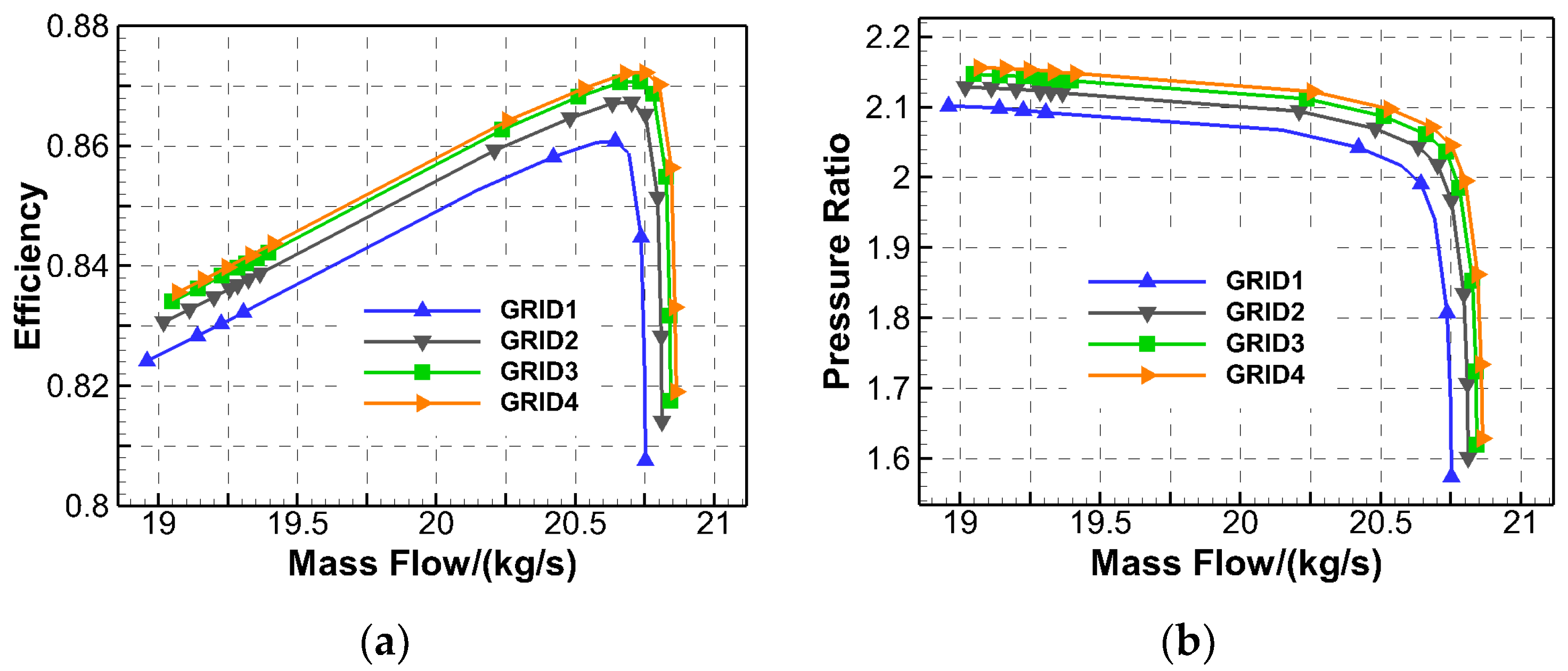
To study the influence of the number of grid nodes in numerical simulation on the flow field structure of the supersonic rotor, the grid independence check of Rotor37 is carried out in this Section. Figure 1 shows the isentropic efficiency and total pressure ratio characteristics of Rotor37 in different grid nodes. The number of grids of GRID1, GRID2, GRID3, and GRID4 was about 0.6 million, 0.8 million, 1 million, and 1.2 million, respectively. The four grids had the same topology structure. It can be seen that with the increase in the number of grid nodes, the peak efficiency and mass flow increased gradually, but when the number of grid nodes was more than 1 million, the increase in the number of grid nodes had little effect on the flow field. An excessive number of grid nodes will significantly increase the computing resources required, which is not conducive to the development and effective conduct of the research. Therefore, the final computing grid of Rotor37 was about 1 million.
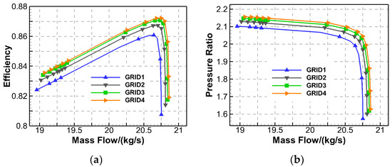
Figure 1.
The isentropic efficiency and total pressure ratio of Rotor37 in different grid nodes. (a) The isentropic efficiency; (b) the total pressure ratio.
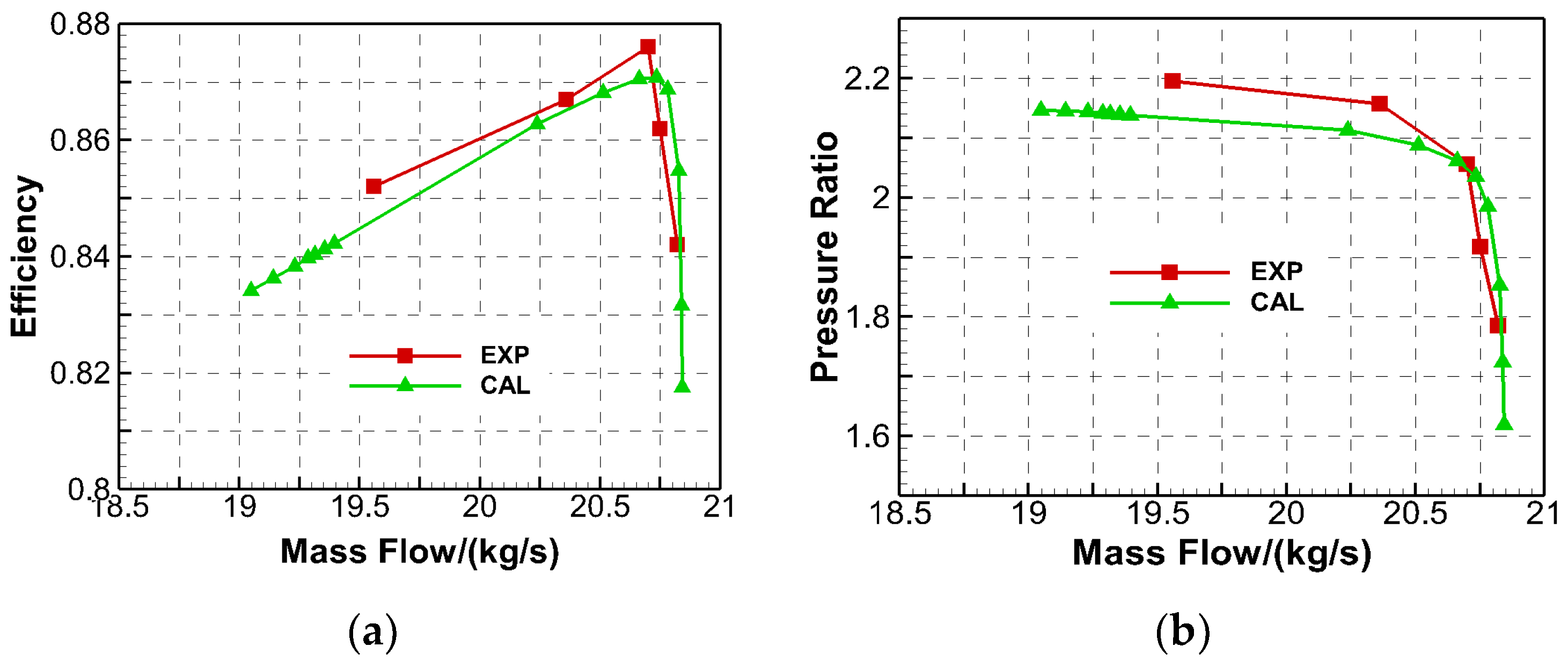
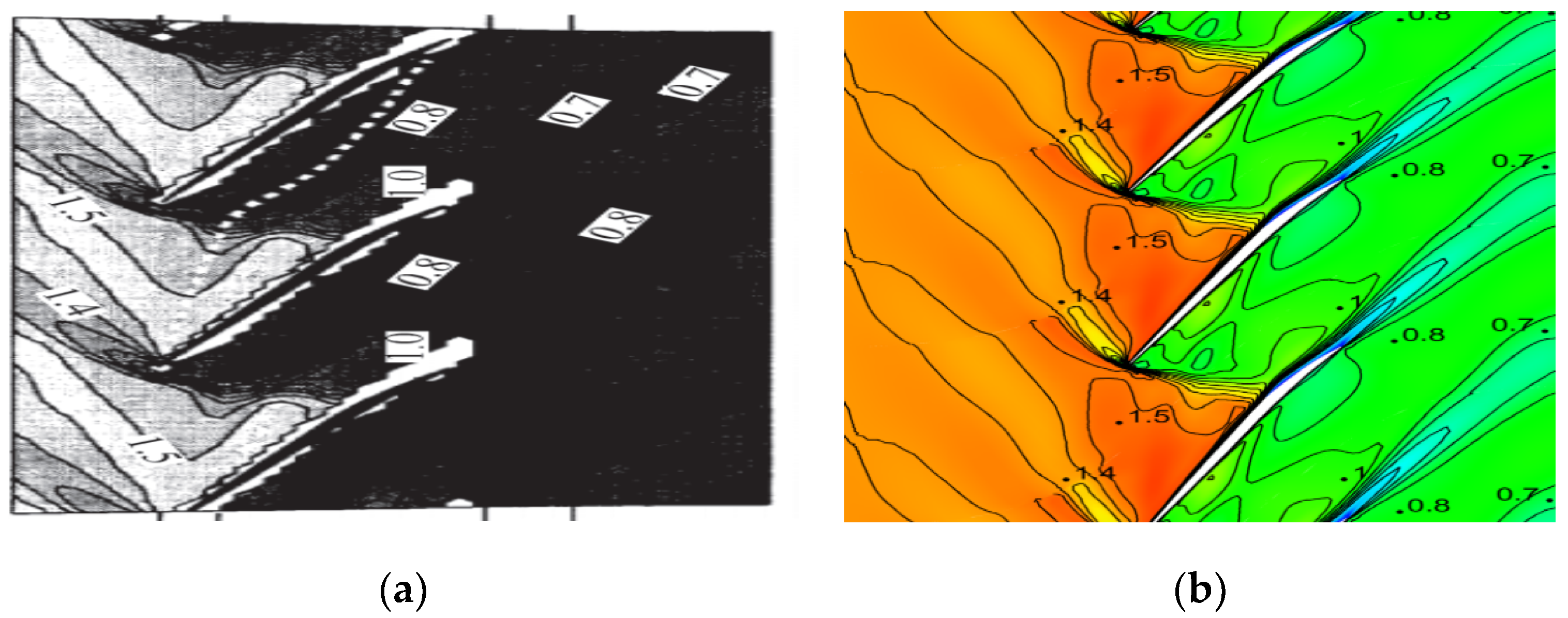
To further verify the accuracy of numerical simulation in performance prediction and flow field structure capture of a supersonic compressor, this paper also carried out a comparative study between numerical simulation results of Rotor37 and experimental results. Figure 2 shows the comparison between the numerical simulation results and the experimental results at the design speed of Rotor37. It was found that the variation trend of the characteristic curve of the numerical model was basically consistent with the experimental results. The maximum efficiency obtained by numerical simulation in this paper was 87.07%, and the corresponding pressure ratio was 2.036. The maximum efficiency was 87.6%, and the corresponding pressure ratio was 2.056. Figure 3 is the comparison between the experimental results and the numerical simulation results of the relative Mach number at 95% blade height at the maximum efficiency point of Rotor37. It can be seen that the Mach number obtained by numerical simulation was basically consistent with the experimental value, which proved that the results of the numerical simulation method in this paper are reliable.
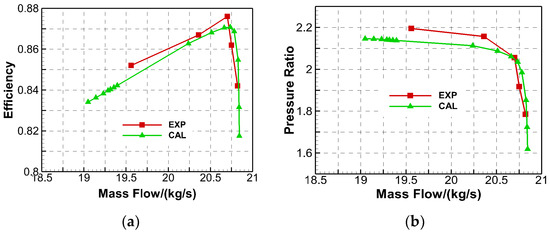
Figure 2.
The comparison of the numerical simulation and the experimental results of Rotor37. (a) The isentropic efficiency; (b) the total pressure ratio.

Figure 3.
The comparison of the relative Mach number at a 95% span at the maximum efficiency point. (a) The experimental results; (b) the numerical simulation results.
3. Design and Analysis of Supersonic Tandem Rotor
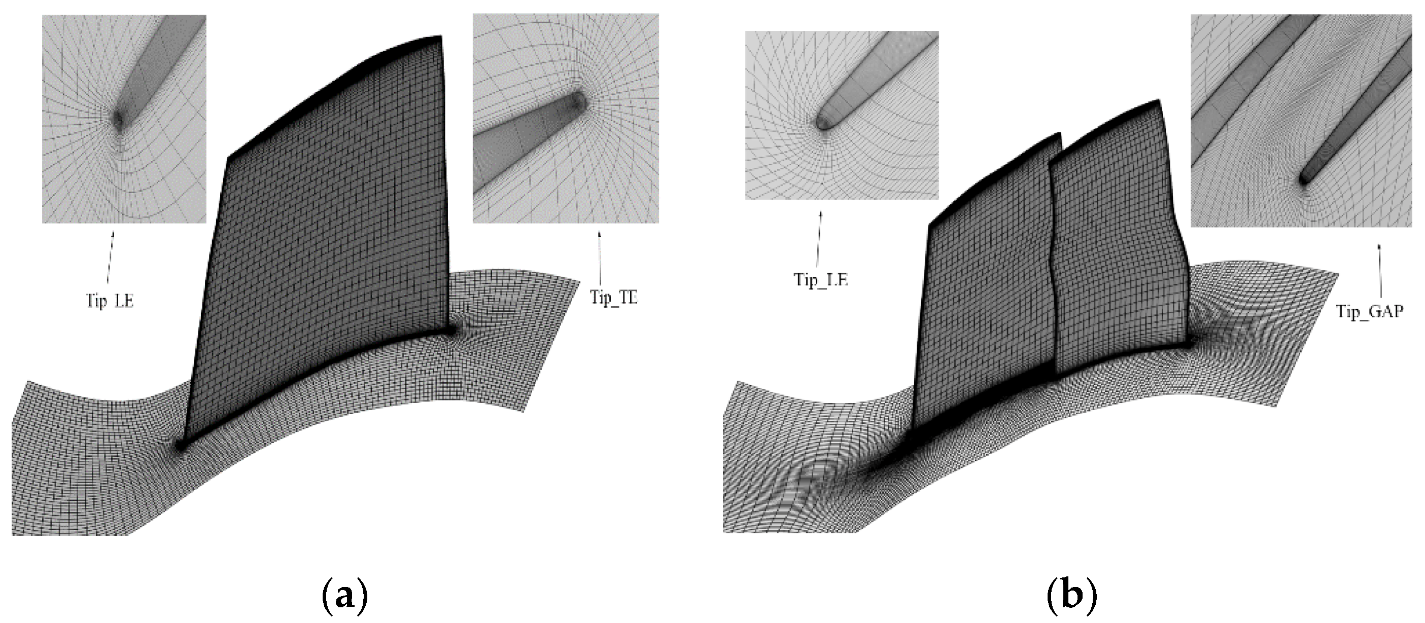
In this paper, the supersonic rotor Rotor37 was taken as the prototype, and five configuration parameters about the relative position of the front and rear blade were selected according to the design experience of the supersonic tandem cascade. Then, Rotor37 was redesigned to a supersonic tandem rotor. Considering that the inlet Mach number of the middle section and tip section of the rotor was relatively high, the precompression cascade was used for both the middle section and tip section to reduce the Mach number and shock loss. According to the numerical simulation method above, the computational grid of the tandem rotor was about 1.8 million. Figure 4 shows the final computational grid of Rotor37 and the tandem rotor. The overall cell count in the tip gap of Rotor37 and tandem rotors was 27 at the spanwise.
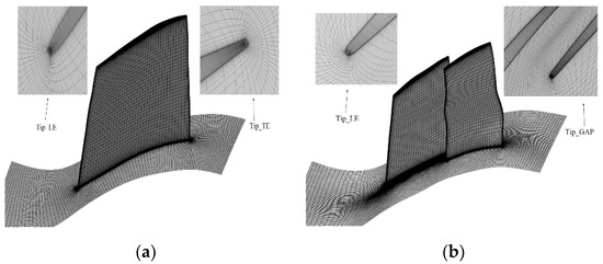
Figure 4.
The final computational grid of Rotor37 and the original tandem rotor. (a) Rotor37; (b) ORG.
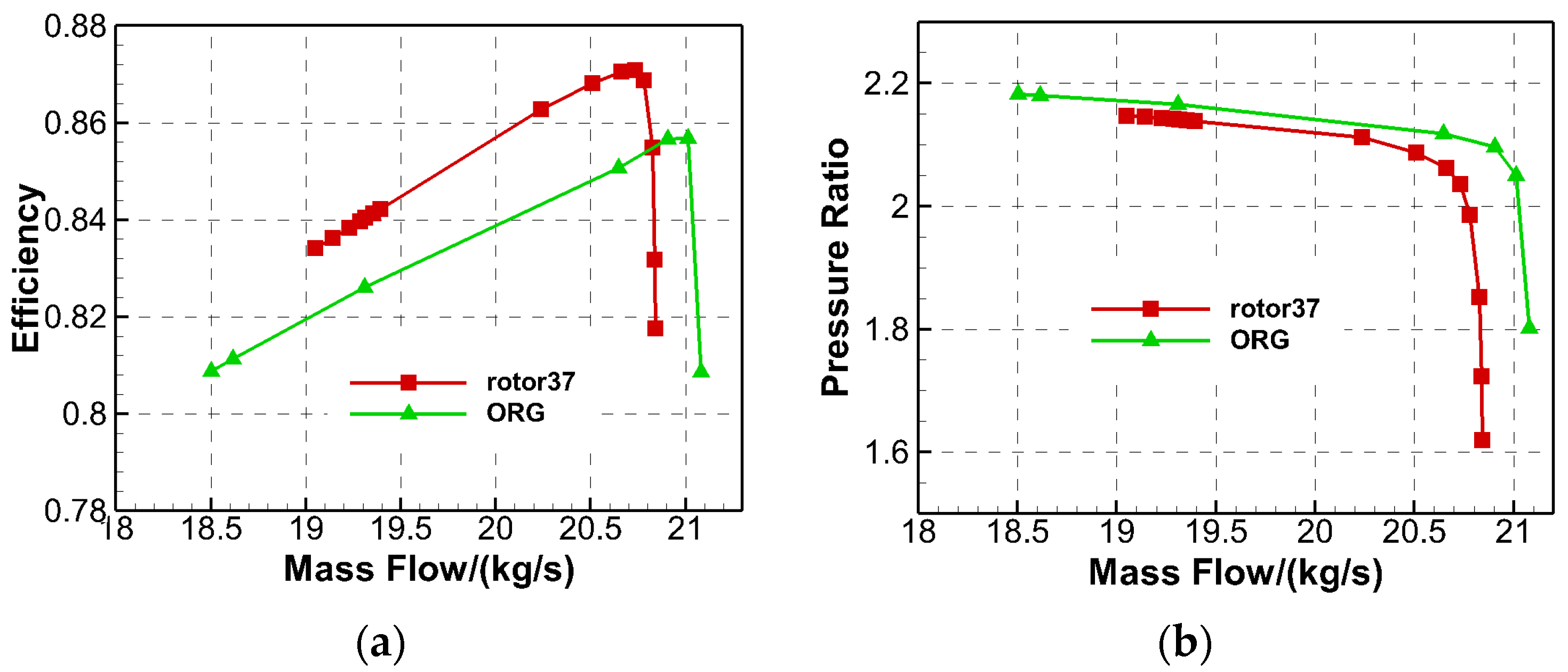
Figure 5 shows the characteristic comparison between Rotor37 and the original tandem rotor at the design speed. This paper selected the peak efficiency point as the rotor design point. As can be seen, compared with the Rotor37, the mass flow and the surge margin of the original tandem rotor obviously increased. However, the efficiency of the tandem rotor was slightly lower than Rotor37. The reason is that as the tandem rotor adopted the initial design blade, the blade surface layer separation is more serious, and the total pressure loss is larger. Therefore, a three-dimensional optimization design of the blades of the original tandem rotor is carried out in the following section.
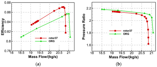
Figure 5.
The characteristic comparison of Rotor37 and the original tandem rotor. (a) The isentropic efficiency; (b) the total pressure ratio.
4. Optimization System
To improve the flow characteristics of the supersonic tandem rotor, this paper studied the optimization design method of supersonic tandem rotor blades. In the optimization, the physical programming method was used to transform the multi-objective problem into the single-objective problem, and the Kriging model was used to create a relationship between the target function and the optimization variable. Then the optimal value of the target function was found by the improved particle swarm optimization algorithm. The main flow chart of the optimization system includes: (1) the optimized Latin hypercube method was used to obtain the sample library, and the numerical model was used to calculate the corresponding value of the objective function of the sample. (2) The Kriging model of the comprehensive preference function of the physical programming method was constructed. (3) The multiple sampling points were obtained based on the improved PSO and the improved parallel multi-point sampling strategy of the Kriging model. (4) The numerical method was used to calculate the value of multiple objective functions and judge whether the convergence conditions were satisfied. If not, the evaluated multiple sampling points were added to the sample base, and the next round of optimization was started again.
4.1. Parameterization Method and Optimization Variables
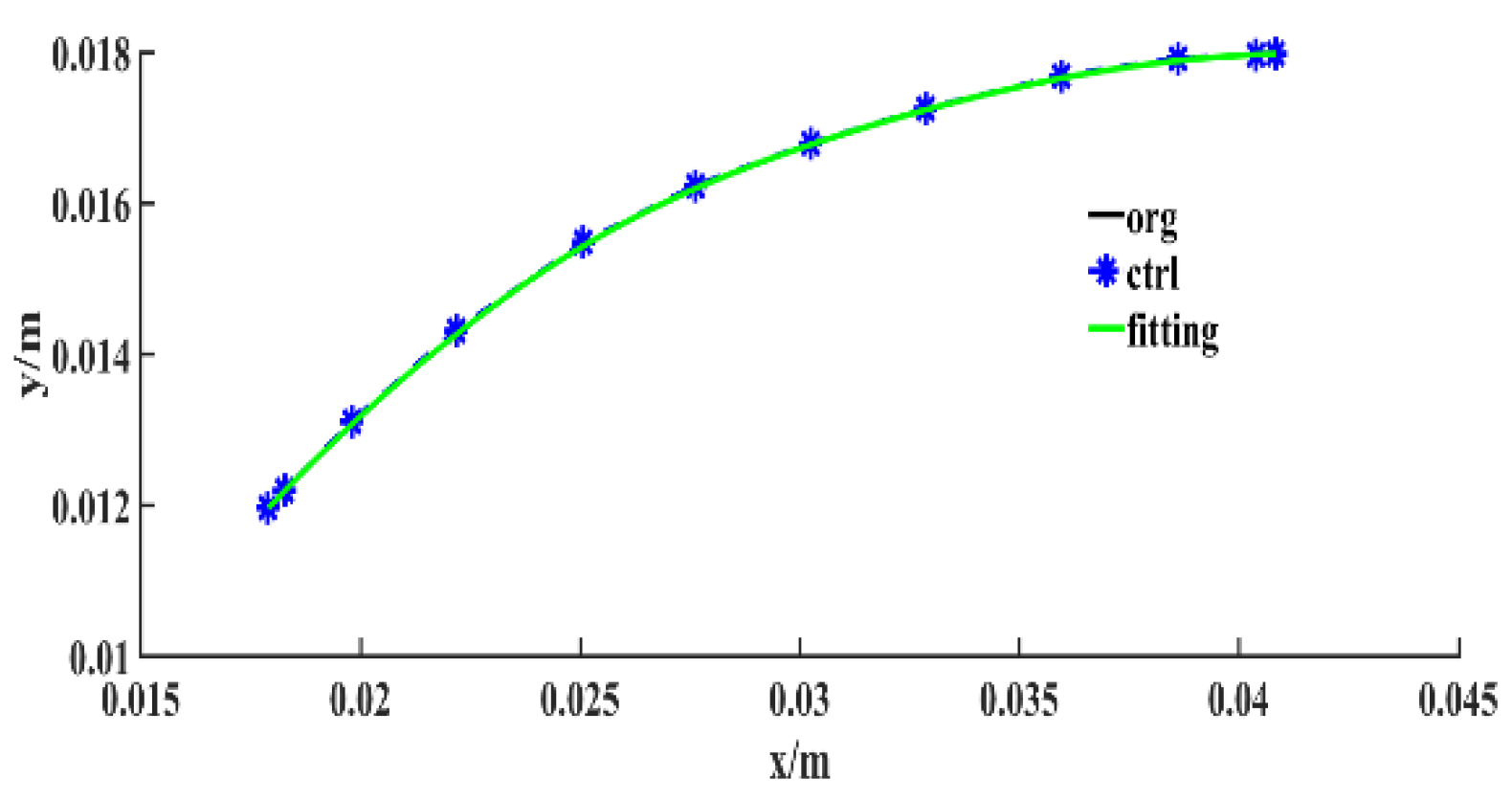
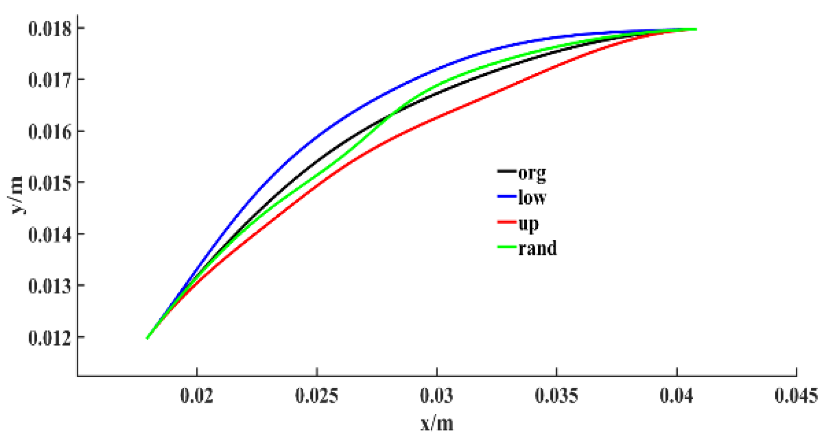
The parameterization of the camber line of the tandem blade and the parameterization of the thickness distribution of the tandem blade were the same as Reference [3] and accomplished by the NURBS method with 12 control points. Compared with the traditional polynomial method, the NURBS method can parameterize complex curves with fewer control points. Besides, the NURBS parameterization method can realize partial modification of complex curves and effectively reduce the number of optimization variables. Figure 6 and Figure 7, respectively, show the parameterization of the camber line and the bound and the rand of the camber line during optimization. In the picture, the ctrl and fitting present the NURBS control points and NURBS line. And the rand presents the sample of the camber line during optimization.

Figure 6.
The parameterization of camber line.
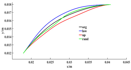
Figure 7.
The bound and the random sample of the camber line during optimization.
During the optimization, to ensure that the inlet and outlet geometric angle remained unchanged in the optimization process, the two control points of the NURBS curves at the beginning and the end remained unchanged, and the other 8 control points of NURBS of the camber line and the thickness distribution were selected as optimization variables of the tandem blade. In the process of NURBS parameterization, the irregular motion of control points may result in unreasonable tandem cascades. Therefore, in this study, the motion direction of control points was defined along the vertical direction of the NURBS curves, so that each of the control points could be described by a vertical coordinate, considering that the flow field structure of the front blade of the tandem rotor was complex and the total pressure loss of the front blade was larger. Besides, the flow field structure of the rear blade was good, and the changes in the geometry shape of the rear blade could not obtain a big effect on the performance of the tandem rotor. Therefore, only the front blade was optimized. The three-section cascade of the hub, mid, and tip section of the front blade was selected as the optimization object. The total number of optimization variables was 48.
4.2. Optimization Objective Function and Constraints
In order not to reduce the surge margin of the supersonic tandem rotor, this paper selected the design point and near stall point of the supersonic tandem rotor as a multi-objective optimization work condition. The optimization objective was to maximize the entropy efficiency of design point and near stall point, and the constraint condition was to ensure that the change of mass flow in the optimization condition was less than the given change limit of mass flow and the total pressure ratio was not less than the total pressure ratio of the original tandem rotor. Equations (1) and (2), respectively, give the constraints of the design point and the near-stall point. The surge margin in this paper is defined as Equation (3).
where and are, respectively, the mass flow of design point and near stall point, and are, respectively, the total pressure ratio of design point and near stall point.
5. Optimization Results and Analysis
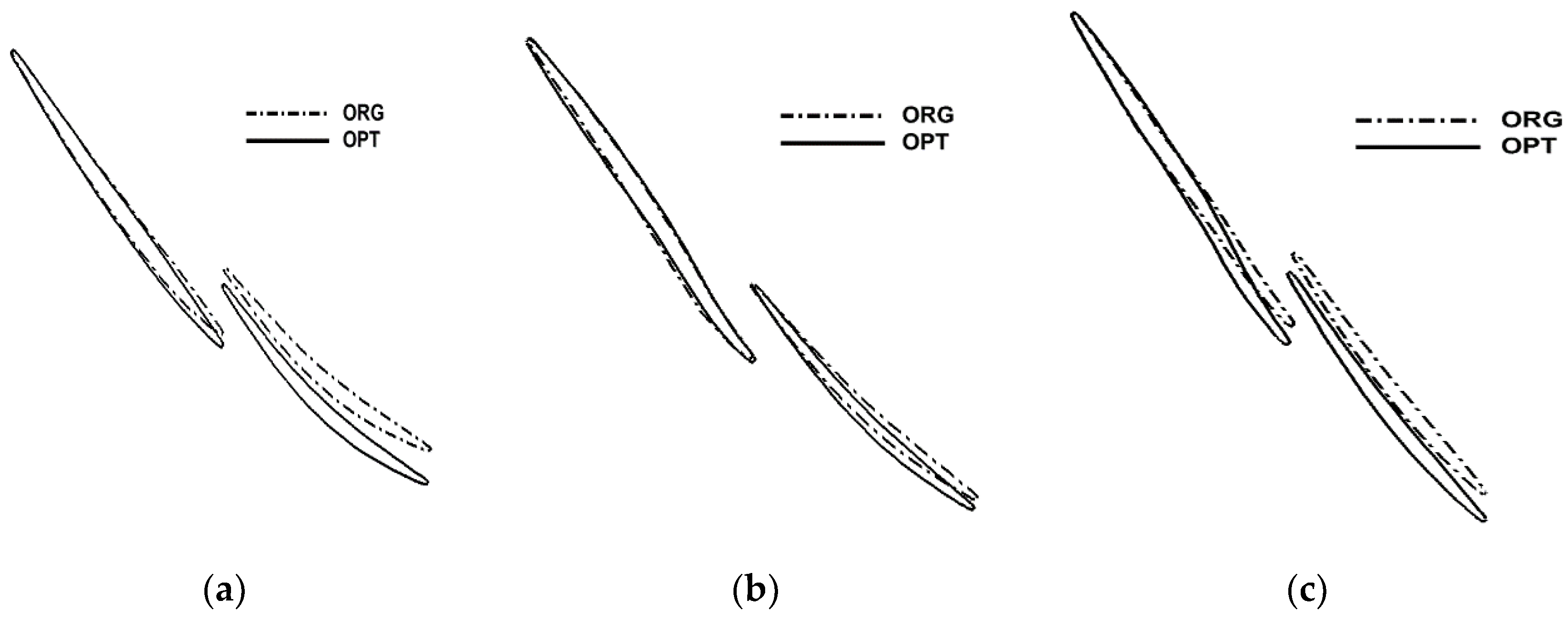
Figure 8 shows the cascade profile comparison of the tandem rotor before and after optimization. For description convenience, ORG represents the original tandem rotor, OPT represents the optimal tandem rotor. It can be seen that compared with the front blade of the original tandem rotor, after optimization, the turn angle of the rear segment of the front blade hub section was smaller, and the degree of precompression in the front segment of the middle section increased, which reduced the Mach number in front of the shock wave and the boundary layer separation loss caused by the shock wave. The expansion degree of the passage in the rear segment of the tip section decreased, and the adverse pressure gradient of the airflow through the blade tip section decreased. Table 2 shows the comparison of the design point performance and surge margin of the original and optimized tandem rotor, Rotor37, is also included in the table. Figure 9 shows the characteristics comparison of Rotor37 and the original and optimized tandem rotor.
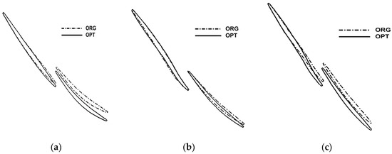
Figure 8.
The cascade profile comparison of the original and optimized tandem rotor. (a) The hub section; (b) the middle section; (c) the tip section.
Table 2.
The performance comparison of Rotor37 and the original and optimized tandem rotor.
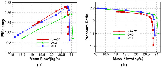
Figure 9.
The characteristics comparison of Rotor37 and the original and optimized tandem rotor. (a) The isentropic efficiency; (b) the total pressure ratio.
It can be seen from Table 2 and Figure 9, compared with the original tandem rotor, the optimized tandem rotor slightly reduced the mass flow at the design point, but the mass flow rate of the optimized tandem rotor was still higher than Rotor37. After optimization, the total pressure ratio and efficiency of the design point obviously increased, and the efficiency increased by 1.6%, and the surge margin increased by 2.75%. It can be seen from the total pressure ratio characteristics that the total pressure ratio of the original and optimized tandem rotor changed little.
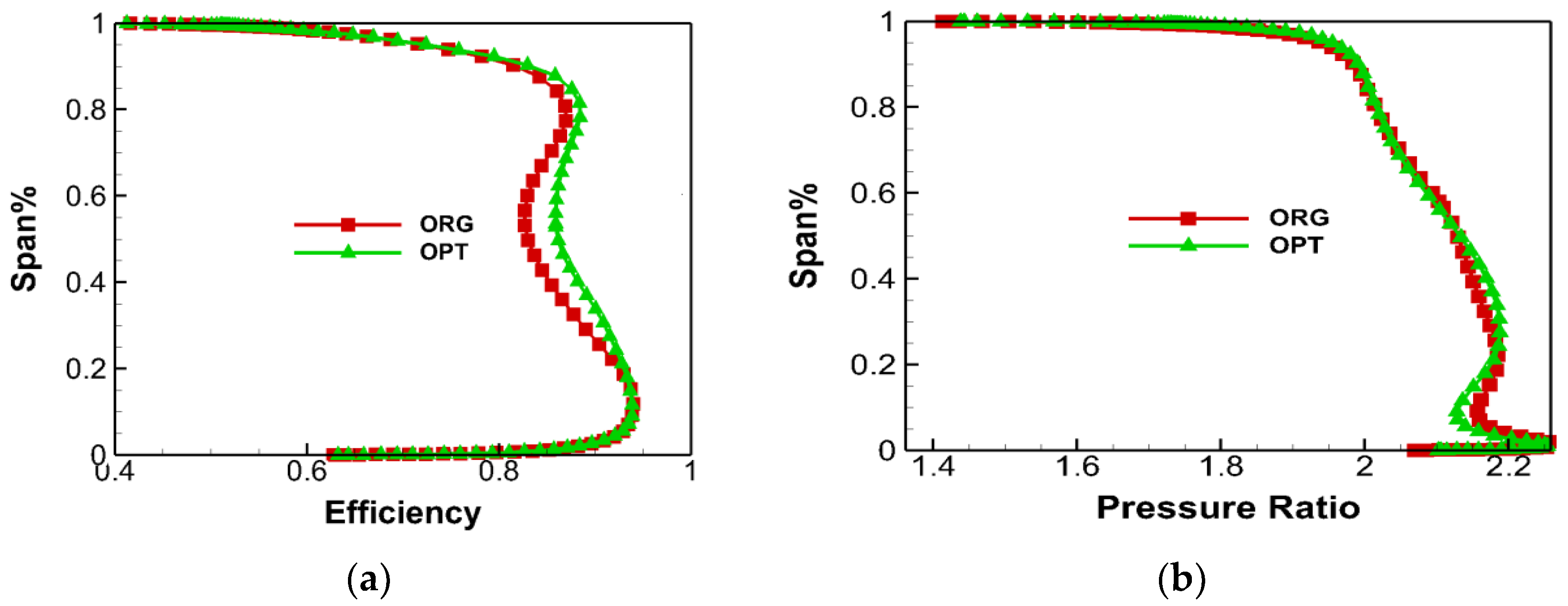
Figure 10 shows the span distribution of the efficiency and total pressure ratio on the design point of the original and optimized tandem rotor. It can be seen that compared with the original tandem rotor, the optimized tandem rotor significantly increased the efficiency of 20–80% span and reduced the total pressure loss of most of the span. Besides, the optimized tandem rotor reduced the total pressure ratio of the hub section, but increased the total pressure ratio and the load near the middle section. To explore the change mechanism of the efficiency and total pressure ratio of the original and optimized tandem rotor, the flow field structure of the tandem rotor was further analyzed.
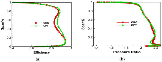
Figure 10.
The span performance of the original and optimized tandem rotor. (a) The efficiency; (b) the total pressure ratio.
Figure 11 shows the relative Mach number of 10% span at the design point of the original and optimized tandem rotor. After optimization, the flow field of the 10% span section of the tandem rotor seldom changed. The strength of the bow shock wave at the leading edge of the front blade was weak, and the upper branch of the bow shock wave at the leading edge extended to the suction surface of the adjacent blade to form a channel shock wave. After the inlet flow passed the shock wave, the subsonic flow continued to decelerate and increase pressure in the expansion channel of the rear blade, and there was no obvious boundary layer separation loss on the suction surface of the front and rear blade.
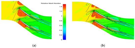
Figure 11.
The relative Mach number of 10% span of the original and optimized tandem rotor. (a) Original tandem rotor (ORG); (b) optimal tandem rotor (OPT).
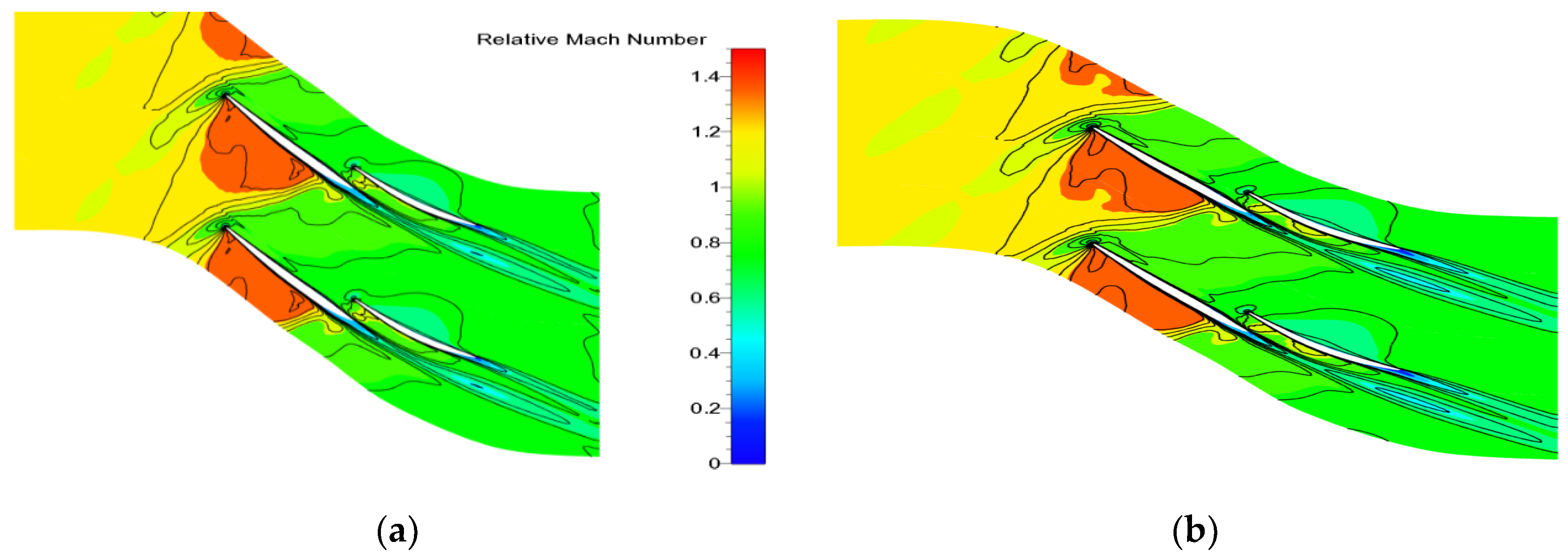
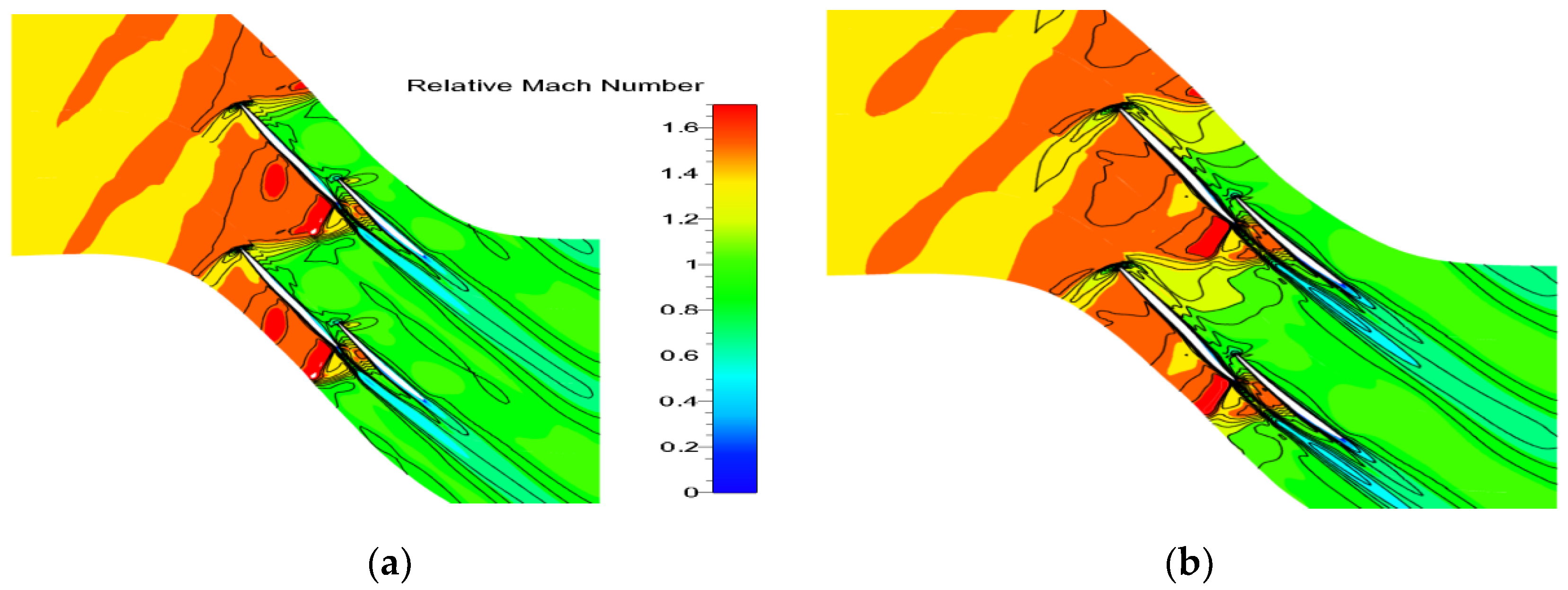
Figure 12 shows the relative Mach number of 50% span at the design point of the original and optimized tandem rotor. It can be seen that to reduce the loss of supersonic speed, the front blade of the original tandem rotor was a precompression blade, and the turning angle of the front blade was negative. The strength of the bow shock wave at the leading edge of the front blade was weak. After passing the lower branch of the bow shock wave, the supersonic flow was still supersonic. In the front segment of the blade, the supersonic inlet flow continued to accelerate and reduce pressure in the expansion channel. Due to the use of a precompression blade, the acceleration of the airflow in the front part of the blade was very small. A local booster deceleration zone appeared in the central segment, while the flow continued to accelerate through the channel shock in the rear segment. After passing the channel shock wave, there was obvious boundary layer separation and low-speed wake zone, and the wake of the front blade progressed to the downstream and mixed with the main flow, which caused an obvious total pressure loss. This is the reason for the low efficiency in the middle section of the original tandem rotor. After optimization, the precompression degree of the front and middle segment of the front blade increased, the trend of the negative turn angle of the front and middle segment of the front blade also increased, and the velocity of the airflow in the front segment was basically unchanged. The degree of deceleration in the middle segment of the blade increased, and the intensity of the shock wave and the boundary layer separation loss after the shock wave reduced, which significantly reduced the mixing loss between the wake of the front blade and the main flow.
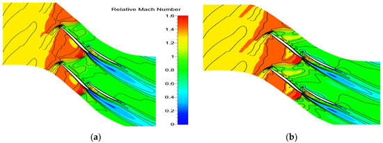
Figure 12.
The relative Mach number of 50% span of the original and optimized tandem rotor. (a) ORG; (b) OPT.
Figure 13 shows the relative Mach number of 90% span at the design point of the original and optimized tandem rotor. It can be seen that the inlet Mach number at the tip section was relatively high. To reduce the shock wave loss caused by supersonic velocity, the precompression blade was adopted at the tip section of the front blade. The turn angle of the front segment of the front blade of the tandem rotor was negative, and the back segment of the front blade was an equal-area straight path. The turn angle of the tandem rotor mainly concentrated in the rear blade. After optimization, the precompression degree of the front blade increased, and an obvious deceleration zone appeared on the suction surface of the front blade, which significantly reduced the Mach number in front of the shock wave and also obviously reduced the shock loss and boundary layer separation loss after the shock wave.

Figure 13.
The relative Mach number of 90% span of the original and optimized tandem rotor. (a) ORG; (b) OPT.
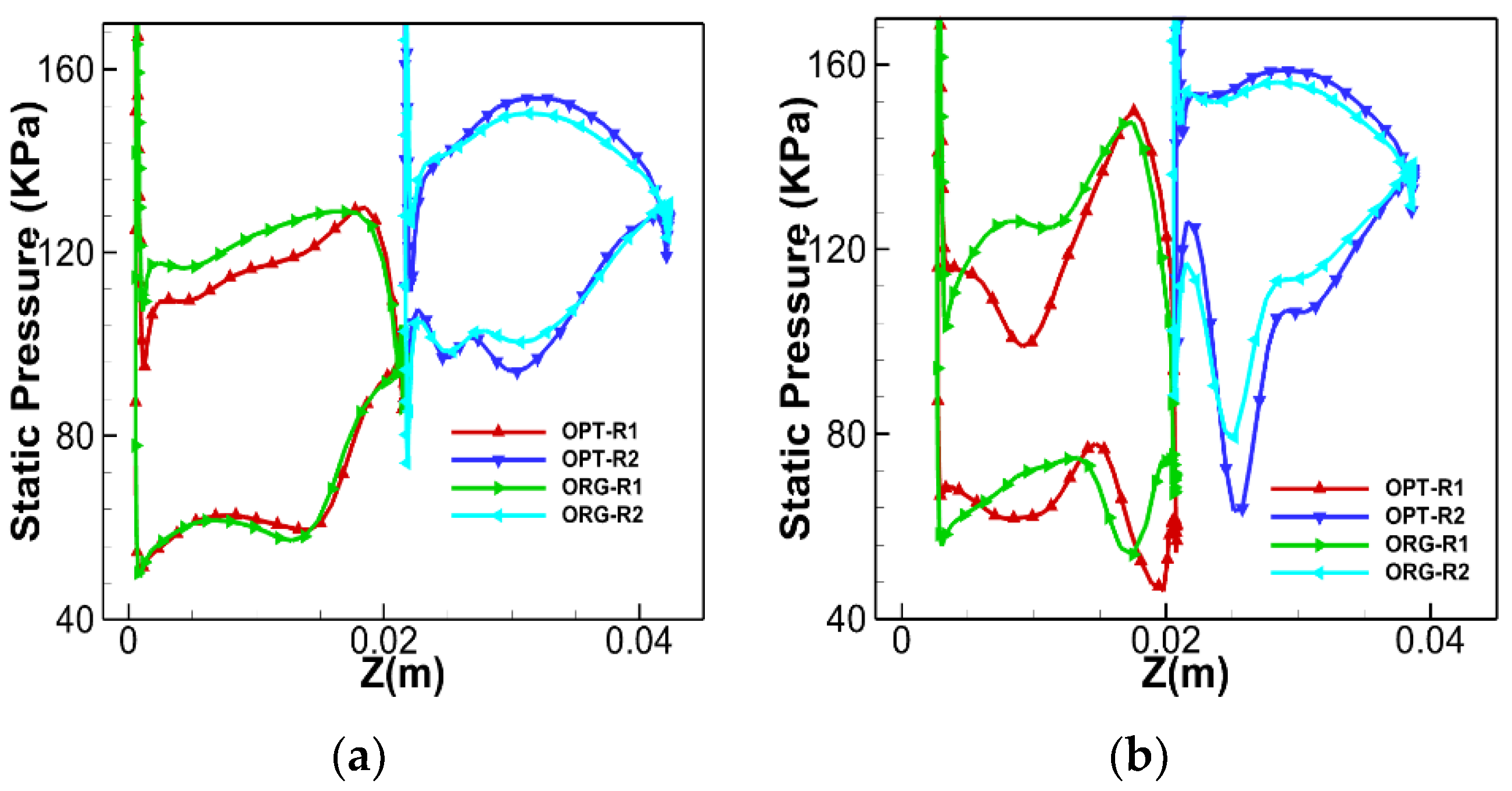
Figure 14 shows the static pressure distribution on the surface of the original and optimized tandem rotor on the design point. It can be seen that the three-dimensional optimization of the front blade of the tandem rotor changed the load distribution of the corresponding blade and had a great impact on the load distribution of the rear blade. At the 10% span section, after the optimization, the static pressure distribution on the suction surface of the front blade was almost unchanged. The static pressure on the pressure surface decreased. The load of the front blade decreased, but the load of the rear blade increased. At the 50% and 90% span, the variation of the load of the tandem rotor was consistent with that of the 10% span. After optimization, the load of the front blade decreased, while the load of the rear blade increased. Based on the above analysis, it can be seen that the reduction in front blade load is conducive to the reduction in tandem rotor shock loss and boundary layer separation loss after the shock wave. Therefore, as the load of the front blades decreased, the low-speed and high-entropy zone of the front blade reduced, the flow field of the front blade improved, the flow field of the rear blade improved, and the diffusion degree and load of the rear blade increased.

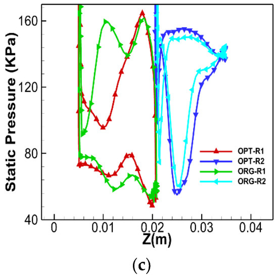
Figure 14.
The static pressure distribution on the surface of the original and optimized tandem rotor. (a) 10% span; (b) 50% span; (c) 90% span.
Besides, the supersonic tandem rotor means the existence of a shock wave, and the shock wave loss and the separation of the boundary layer after the shock wave were also obvious. As can be seen from the relative Mach number image (Figure 11 and Figure 13), for the rear blade, the position of the shock wave could be approximated by the position of the sudden rise of the static pressure on the suction surface of the blade. The front blade was different from the normal supersonic blade. The hub section was the same as the normal supersonic blade, but the middle section and tip section was not the same as the normal supersonic blade. For the middle and tip sections of the front blade, the position of the sudden rise of the static pressure on the pressure surface can be approximated as the position of the shock wave. As can be seen from Figure 14, the three-dimensional optimization of the front blade changes the position of the shock wave in the front blade, and the shock wave moved to the trailing edge of the front blade. The shock wave in the blade hub section moved to the trailing edge at a smaller distance. But the shock wave in the middle and tip section moved to the trailing edge at a larger distance. The shock wave moved from the front edge of the pressure surface to the middle of the pressure surface. Due to the use of a precompression blade, the deceleration degree of the supersonic flow increased as the shock wave moved to the trailing edge of the blade, which reduced the intensity of the shock wave and the boundary layer separation zone caused by the shock wave.
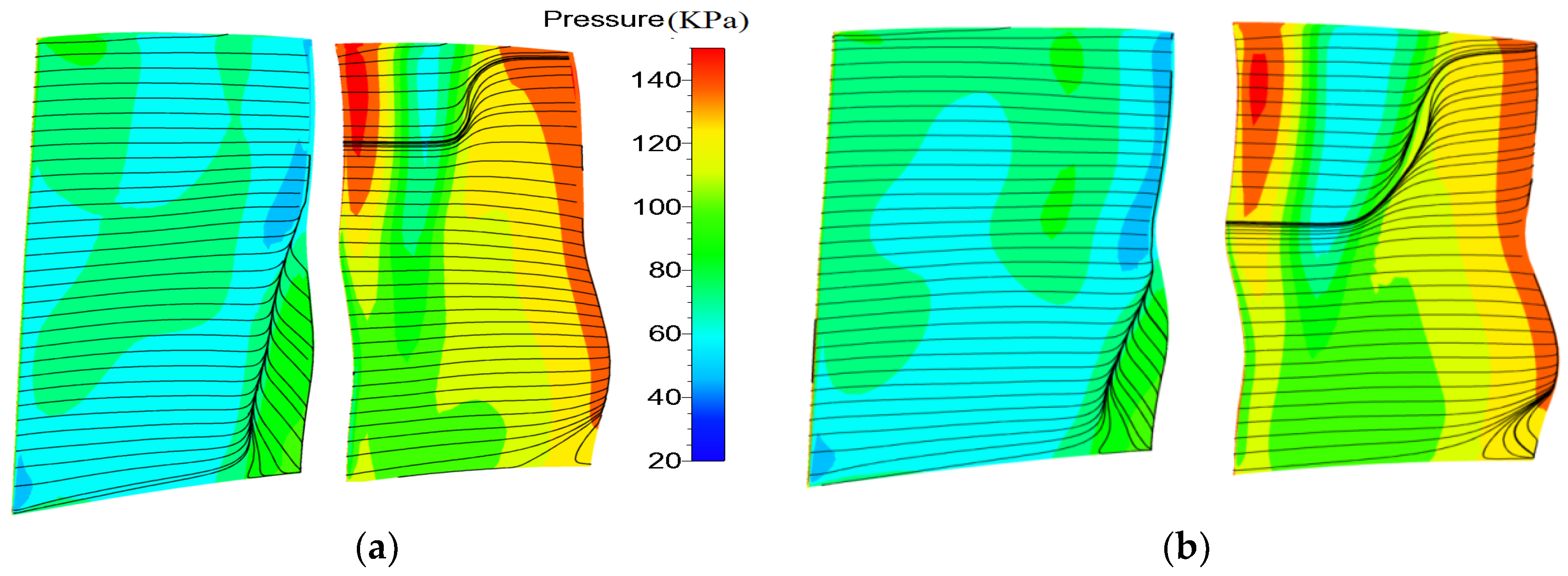
Figure 15 shows the surface static pressure and streamline of the suction surface of the original and optimized tandem rotor. There was an obvious separation line at the hub and middle section of the suction surface of the front blade of the original tandem rotor, and the position of the separation line extended from 10% span to 60% span. The separation line was generated by the boundary layer separation caused by the shock wave. Near the hub section of the front blade, there was obvious angular separation caused by radial migration of the end wall boundary layer. The three-dimensional optimization of the front blade significantly reduced the boundary layer separation range in the middle section of the front blade. The position of the separation line extended from the 10% span to about the 40% span, which improved the flow field structure in the middle section of the tandem rotor. On the suction surface of the rear blade of the optimized tandem rotor, the low-energy fluid in the middle section had radial migration to the tip section due to the action of centrifugal force, and the range of radial migration of the boundary layer was larger than that of the original rotor. However, there was no obvious boundary layer separation line on the suction surface of the rear blade. This is because the airflow on the rear blade was subsonic, and the proper boundary layer migration from the middle section to the tip section can improve the flow field in the blade.
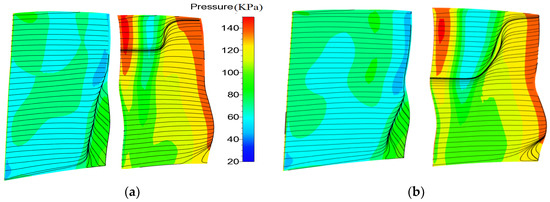
Figure 15.
Static pressure and streamline of the suction surface of the original and optimized tandem rotor. (a) ORG; (b) OPT.
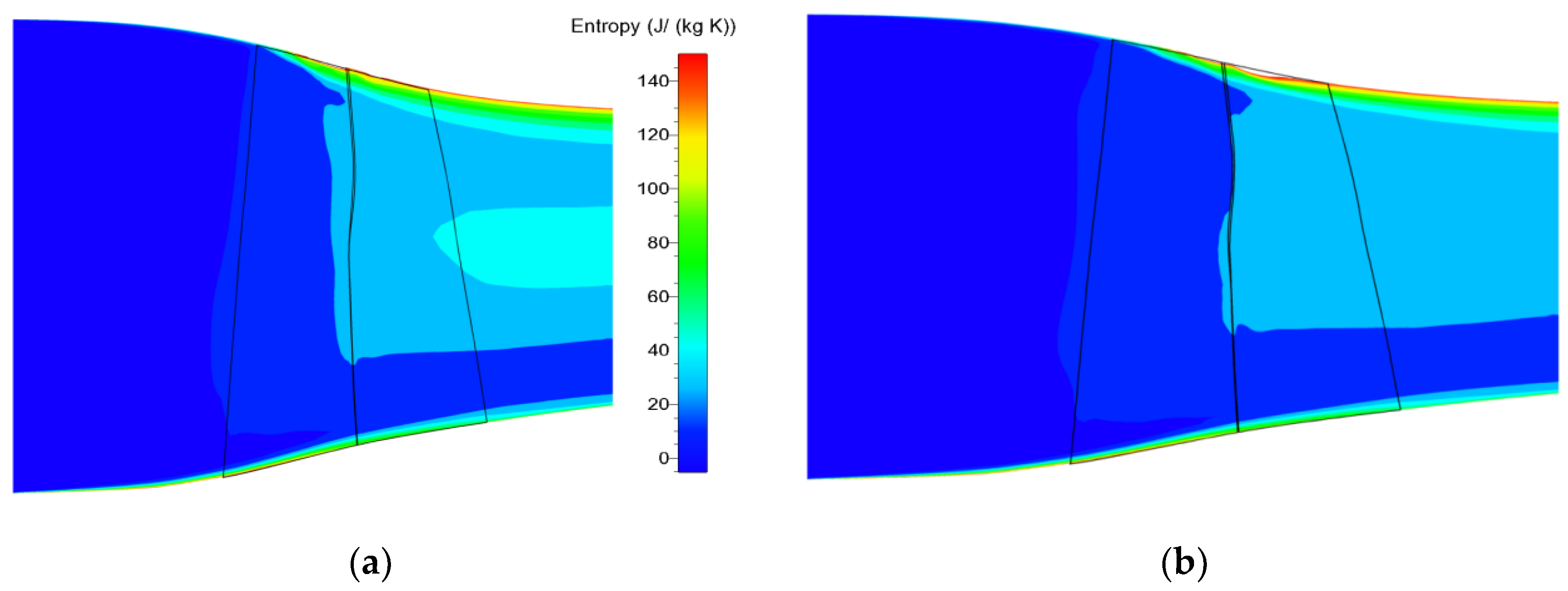
Figure 16 shows the entropy distribution of the mean flow surface of the original and optimized tandem rotor. It can be seen that there was an obvious high loss area in the middle section of the rear blade of the original tandem rotor, which was mainly caused by the mixing loss between the wake of the front blade and the main flow. After optimization, the high-loss area from the 20% span to the 90% span of the trailing edge of the front blade was significantly reduced, and the high-loss area was mainly caused by the shock wave loss and the boundary layer separation loss. At the same time, the high-loss area in the middle section of the rear blade was also significantly reduced, which indicates that the blade optimization significantly improved the flow field in the middle section of the blade and reduced the mixing loss between the low-energy fluid in the blade wake and the main flow.
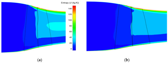
Figure 16.
The entropy distribution of the mean flow surface of the original and optimized tandem rotor. (a) ORG; (b) OPT.
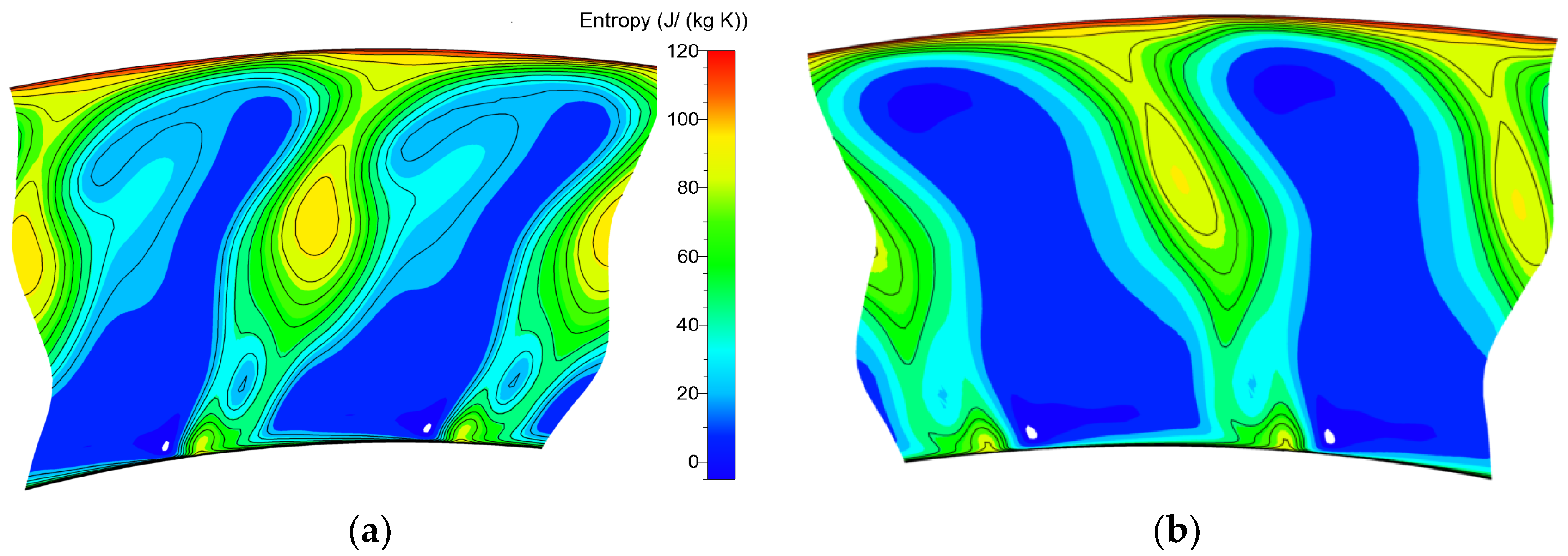
Figure 17 shows the entropy distribution of the S3 surface at the outlet of the original and optimized tandem rotor on the design point. It can be seen that after optimization, the range and intensity of the high-loss region in the middle section of the tandem rotor significantly decreased, while the range of the low-loss area in the middle region and tip region was significantly increased, but the range and strength of the high-loss area in the tip region changed little. From the above analysis, it can be seen that the reason for the decrease of total pressure loss in the middle region and tip region is that the three-dimensional optimization of the blade significantly reduced the shock loss and boundary layer separation loss of the front blade. At the same time, the mixing loss between low energy fluid and the main flow in blade wake reduced. Comparing with the entropy distribution in tip area of the original and optimized tandem rotor, it was found that the total pressure loss in the tip area was seldom changed, which indicates that the three-dimensional optimization of the blade did not significantly improve the flow field in the tip area, and had little impact on the leakage flow and the secondary flow generated by the mutual interference of the leakage flow and shock wave.
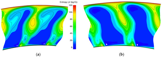
Figure 17.
The entropy distribution of the S3 surface at the outlet of the original and optimized tandem rotor. (a) ORG; (b) OPT.
6. Conclusions
In this study, to explore the flow mechanism and improve the performance of supersonic tandem rotor blades, the supersonic rotor Rotor37 was taken as the prototype and redesigned to an original supersonic tandem rotor. And then, a multi-objective optimization methodology was developed and applied to achieve the optimization design of the supersonic tandem rotor blades. The main conclusions from the current research are as follows.
- (1)
- Compared with Rotor37, the mass flow and the surge margin of the original tandem rotor obviously increased. However, the efficiency of the original tandem rotor was slightly lower than Rotor37. The reason is that the original tandem rotor adopted the initial design blade, the blade surface layer separation was more serious, and the total pressure loss was larger.
- (2)
- After multi-objective optimization, compared with the original tandem rotor, the total pressure ratio and efficiency of the optimized tandem rotor significantly increased, and the efficiency increased by 1.6%, and the surge margin increased by 2.75%.
- (3)
- The range and intensity of the high-loss region in the middle section of the optimized tandem rotor significantly decreased, and the range of the low-loss area in the middle region and tip region significantly increased, but the range and strength of the high-loss area in the tip region changed little. The reason for the decrease of total pressure loss in the middle region and tip region is that the three-dimensional optimization of the blade significantly reduced the shock loss and boundary layer separation loss of the front blade. At the same time, the mixing loss between low energy fluid and the main flow in blade wake also reduced.
- (4)
- The three-dimensional optimization of the blade did not significantly improve the flow field in the tip area and had little impact on the leakage flow and the secondary flow generated by the mutual interference of the leakage flow and shock wave.
Author Contributions
The research is initially proposed by R.P. and B.L. The manuscript is further improved by Z.S. All authors have read and agreed to the published version of the manuscript.
Funding
This paper was funded by the Natural Science Foundation of China (No. 51676162).
Conflicts of Interest
The authors declare no conflict of interest.
References
- Sanger, N.L. Analytical Study of the Effects of Geometric Changes on the Dlow Characteristics of Tandem-Bladed Compressor Stators; NASA TN-D-6264; National Aeronautics and Space Administration: Washington, DC, USA, 1971.
- Railly, J.W.; El-Sarha, M.E. An Investigation of the Flow through Tandem Cascades. In Proceedings of the Institute of Mechanical Engineers, 1965–1966; SAGE Publications: London, UK, 1965; Volume 180, pp. 66–73. [Google Scholar]
- Zhaoyun, S.; Bo, L. Optimization design for tandem cascades of compressors based on adaptive particle swarm optimization. Eng. Appl. Comput. Fluid Mech. 2018, 12, 535–552. [Google Scholar]
- Sulana, D.H.; Keenan, M.J.; Flynn, J.T. Single-Stage Experimental Evaluation of Highly-Loaded High-Mach-Number Compressor Stages. Part 2: Data and Performance Multiple-Circular-Arc Rotor; NASA-CR-72694; National Aeronautics and Space Administration: Washington, DC, USA, 1970.
- Brent, J.A.; Cheatham, J.G.; Nilsen, A.W. Single-Stage Experimental Evaluation of Tandem-Airfoil Rotor and Stator Blading for Compressors; NASA-CR-120803; National Aeronautics and Space Administration: Washington, DC, USA, 1972.
- Brent, J.A.; Clemmons, D.R. Single-Stage Experimental Evaluation of Tandem-Airfoil Rotor and Stator Blading for Compressors. Part 8: Final Report; NASA-CR-134713; National Aeronautics and Space Administration: Washington, DC, USA, 1974.
- Brent, J.A.; Cheatham, J.G.; Clemmons, D.R. Single-Stage Ex-Perimental Evaluation of Tandem-Airfoil Rotor and Stator Blading for Compressors. Part 5: Analysis and Design of Stages D and E; NASA-CR-121008; National Aeronautics and Space Administration: Washington, DC, USA, 1972.
- Brent, J.A.; Cheatham, J.G. Single-Stage Experimental Evaluation of Tandem-Airfoil Rotor and Stator Blading for Compressors. Part 4: Data and Performance for Stage B; NASA-CR-121145; National Aeronautics and Space Administration: Washington, DC, USA, 1973.
- Wu, G.; Zhuang, B.; Guo, B. Experimental Investigations of Tandem Blade Cascades with Double Circular Arc Profiles. In Proceedings of the ASME 1985 Beijing International Gas Turbine Symposium and Exposition, Beijing, China, 1–7 September 1985. ASME paper 85-IGT-94. [Google Scholar]
- Roy, B.; Saha, U.K. Experimental Analysis of Controlled Diffusion Compressor Cascades with Single and Tandem Airfoils. In Proceedings of the ASME 1995 International Gas Turbine and Aeroengine Congress and Exposition, Houston, TX, USA, 5–8 June 1995. ASME paper 95-CTP-41. [Google Scholar]
- Roy, B.; Saha, U.K. On the Application of Variable Camber Blading in Axial Flow Fans and Compressors. In Proceedings of the ASME 1996 Turbo Asia Conference, Jakarta, Indonesia, 5–7 November 1996. ASME paper 96-TA-58. [Google Scholar]
- Bammeert, K.; Staude, R. New features in the design of axial-flow compressors with tandem blades. In Proceedings of the ASME 1981 International Gas Turbine Conference and Products Show, Houston, TX, USA, 9–12 March 1981. ASME Paper n81-GT-113. [Google Scholar]
- Bammert, K.; Staude, R. Optimization for Rotor Blades of Tandem Design for Axial Flow Compressors. ASME79-GT-125. J. Eng. Power 1980, 102, 369–375. [Google Scholar] [CrossRef]
- Bammert, K.; Beelte, H. Investigation of an Axial-Flow Compressor with Tandem Cascades. ASME-80-GT-93. J. Eng. Power 1980, 102, 971–977. [Google Scholar] [CrossRef]
- McGlumphy, J.; Ngm, W.F.; Wellborn, S.R.; Kempf, S. Numerical Investigation of Tandem Airfoils Subsonic Axial-Flow Tandem Compressor Blades. ASME 2007-GT-43929. J. Turbomach. 2009, 131, 021018. [Google Scholar] [CrossRef]
- McGlumphy, J.; Ng, W.F.; Wellborn, S.R. 3D Numerical Investigation of Tandem Airfouls for a Core Compressor Rotor. ASME 2008-GT-50427. J. Turbomach. 2010, 132, 031009. [Google Scholar] [CrossRef]
- Urasek, D.C.; Janetzke, D.C. Performance of Tandem-Bladed Transonic Compressor Rotor with Tip Speed of 1375 Feet per Second; NASA TM X-2484; National Aeronautics and Space Administration: Washington, DC, USA, 1972.
- Hasegawa, H.; Matsuoka, A.; Suga, S. Development of highly loaded fan with tandem cascade. In Proceedings of the 41st Aerospace Sciences Meeting and Exhibit, Reno, NV, USA, 6–9 January 2003. AIAA Paper 2003 p. 1065. [Google Scholar]
- Sakai, Y.; Matsuoka, A.; Suga, S.; Hashimoto, H. Design and Test of Transonic Compressor Rotor with Tandem Cascade. In Proceedings of the International Gas Turbine Congress, Tokyo, Japan, 2–7 November 2003. [Google Scholar]
- Yuan, T.; Xianjun, Y.; Baojie, L. Analysis of matching characteristic of transonic tandem stator airfoil and its optimization. J. Aerosp. Power 2012, 27, 2278–2286. [Google Scholar]
- Zhao, B.; Liu, B. Analysis of Transonic Tandem Rotor and Matching Characteristic of Forward and Aft Blades. Chin. J. Aeronaut. 2011, 32, 978–987. [Google Scholar]
- Forrester, A.I.J.; Keane, A.J. Recent Advances in Surrogate-Based Optimization. Prog. Aerosp. Sci. 2009, 45, 50–79. [Google Scholar] [CrossRef]
- Mcallister, C.D.; Simpson, T.W.; Hacker, K.; Lewis, K.; Messac, A. Integrating Linear Physical Programming Within Collaborative Optimization for Multiobjective Multidisciplinary Design Optimization. Struct. Multidiscip. Optim. 2005, 29, 178–189. [Google Scholar] [CrossRef]
- Zhaoyun, S.; Bo, L.; Hao, C. Adaptive particle swarm optimization with population diversity control and its application in tandem blade optimization. Proc. Inst. Mech. Eng. Part C J. Mech. Eng. Sci. 2019, 6, 1859–1875. [Google Scholar]
- Han, L.; Yuan, W.; Wang, Y. Influence of tip leakage flow and ejection on stall mechanism in a transonic tandem rotor. Aerosp. Sci. Technol. 2018, 77, 499–509. [Google Scholar] [CrossRef]
- Spalart, P.R.; Allmaras, S.R. A One Equation Turbulence Model for Aerodynamic Flows. In Proceedings of the 30th Aerospace Sciences Meeting and Exhibit, Reno, NV, USA, 6–9 January 1992. AIAA Paper 92-0439. [Google Scholar]
- Payyappalli, M.M.; Shine, S.R. Numerical Investigation on Tandem Compressor Cascades. In Proceedings of the ASME 2015 Gas Turbine India Conference, Hyderabad, India, 2–3 December 2015. ASME Paper GTINDIA2015-1311. [Google Scholar]
- Boehle, M.; Frey, T. Numerical and experimental investigations of three-dimensional flow structure of tandem cascades in the sidewall region. J. Fluids Eng. 2014, 136, 071102. [Google Scholar] [CrossRef]
- Reid, R.D.; Moore, L. Design and Overall Performance of Four Highly Loaded, High-Speed Inlet Stages for an Advanced High-Pressure Ratio Core Compressor; NASA Technical Paper 1337; National Aeronautics and Space Administration: Washington, DC, USA, 1978.
- Reid, L. Performance of Single Stage Transonic AFC Rotor and Stator Aspect Ratio of 1.19 and 1.26, Resp. and with Design Pressure Ratio of 2.05; NASA Technical Paper 1659; National Aeronautics and Space Administration: Washington, DC, USA, 1980.


© 2020 by the authors. Licensee MDPI, Basel, Switzerland. This article is an open access article distributed under the terms and conditions of the Creative Commons Attribution (CC BY) license (http://creativecommons.org/licenses/by/4.0/).