Abstract
Air source heat pumps (ASHPs) are widely recognized as energy-saving and environmentally friendly heating and air-conditioning equipment with broad applications. However, when conventional ASHPs are operated at a low ambient temperature, they suffer from problems such as high discharge temperature and low heating efficiency. To address these problems, this study designed a new type of dual evaporator combined with a compressor casing thermal storage heat pump system (DE-CCTS) on the basis of a low-temperature air source heat pump water heater with enhanced vapor injection (EVI). The proposed DE-CCTS used thermal storage phase change material (PCM), which was filled in the secondary evaporator (the thermal storage heat exchanger), to recover the waste heat of the compressor casing. Unlike that in the original system under different ambient temperatures, the suction temperature increased by 0.1–1 °C, the discharge temperature decreased by 0.1–0.5 °C, and the coefficient of performance (COP) of DE-CCTS increased by 0.85–4.72% under the proposed system. These effects were especially evident at low temperatures.
1. Introduction
With the development of the global economy, energy shortage and environmental pollution have become major global problems. Air source heat pumps (ASHPs), as clean and efficient heating devices, have broad applications. However, when ASHPs are used in extreme temperatures, they suffer from problems such as low heating efficiency and excessively high compressor discharge temperature [1,2,3]. Researchers have proposed many solutions to these problems, such as the addition of auxiliary heating systems, the use of two-stage or multistage compression cycles, and the use of enhanced vapor injection (EVI). Existing studies have helped broaden the use of ASHPs, especially those with EVI, which has become a research hotspot in this field with good comprehensive performance [4,5].
Wang [6] reported that rotary compressors encounter severe performance degradation at low ambient temperatures, and thereby introduced a rotary compressor prototype with a novel end-plate injection structure. Compared with a single-stage rotary compressor, the proposed rotary compressor with a novel end-plate injection structure enhanced the heating capacity and coefficient of performance (COP) by 16.2–31.6% and 5.1–12.0%, respectively. Chen [7] proposed a new direct-expansion solar-assisted vapor injection heat pump cycle with a subcooler for water heaters to improve the performance of traditional subcooler vapor injection heat pump cycles using solar energy. Under the considered conditions, the new cycle yielded average improvements of 14.6% and 42.9% in heating COP and heating capacity, respectively, relative to the traditional cycle. Both cycles have optimum injection pressures to obtain the maximum heating COP. Xu [8] adopted a newly designed vapor-injected heat pump using injection subcooling to improve the heating performance of an R32 heat pump at cold regions. The vapor injection with subcooling further decreased the R32 compression discharge temperature. Qi [9] discussed a novel hybrid vapor injection cycle (HVIC) with a subcooler and flash tank for ASHPs. In the HVIC, an ejector is applied to realize the advantages of the subcooler and flash tank vapor injection. In this manner, the irreversible thermodynamic loss can be efficiently reduced, and the system performance can be improved, especially at low ambient temperatures. Wang [10] proposed a novel ejector enhanced vapor injection cycle (EVIC) for ASHPs. In the EVIC, an ejector associated with an additional flash tank is introduced to enhance the overall system performance at low ambient temperatures.
However, a certain amount of heat from the operation of compressors is usually dissipated to the ambient environment. Ooi [11] estimated that 10–20% of the total power was dissipated to the ambient environment through the compressor casing by convection and conduction. Park [12] indicated that the heat dissipating from the compressor was approximately 6.3% of the total power. In other words, over a period of time, a considerable amount of heat energy is dissipated to the surrounding environment through the compressor casing.
Liu’s group studied the heat utilization of compressor casings and identified considerable effects. Liu [13] proposed a constant temperature water immersion thawing system using fixed-frequency refrigerator compressor casing heat storage. The new system reduced the compressor casing and discharge temperature by 3.8 °C and 2.5 °C, respectively; and its water loss rate was only 15.9% of that of microwave thawing. Liu [14] studied the defrosting system of an ASHP utilizing compressor casing heat storage combined with a hot gas bypass cycle. The compressor casing temperature of the new system was reduced by 4.6 °C, and the new system exerted the least influence on the indoor temperature among the other defrosting methods. Liu [15] developed a bypass cycle defrosting system using fixed-frequency refrigerator compressor casing thermal storage. The experimental results revealed that the defrosting time and defrost energy consumption decreased by 65–77% and 89–92%, respectively, relative to the results of the 180–419 W electric heater defrosting method. In order to use the heat of the compressor casing for defrosting, Zhang [16] designed a novel ASHP and found that in the new system, the discharge and suction pressure increased by 0.33 and 0.14 MPa, respectively, and the defrosting time was shortened by 65%. A study that motivated the current work is that of Huang [17], who proposed a novel heat recovery device that reuses the heat of a compressor casing to avoid liquid slugging and supplement a certain amount of heat into the system under low temperatures. The suction temperature rose from 295.45 K to 320.55 K, thus indicating that the new system successfully delivered heat from the compressor casing to the refrigerant.
In the present study, a new type of dual evaporator combined with a compressor casing thermal storage heat pump system (DE-CCTS) was proposed, which recovered the waste heat of compressor casings to improve the suction temperature and supplement a certain amount of heat into the system under low temperatures. For the purpose of comparison, experiments using the original system and the proposed DE-CCTS were conducted. The results were analyzed after the experiments.
2. Operating Principle of DE-CCTS
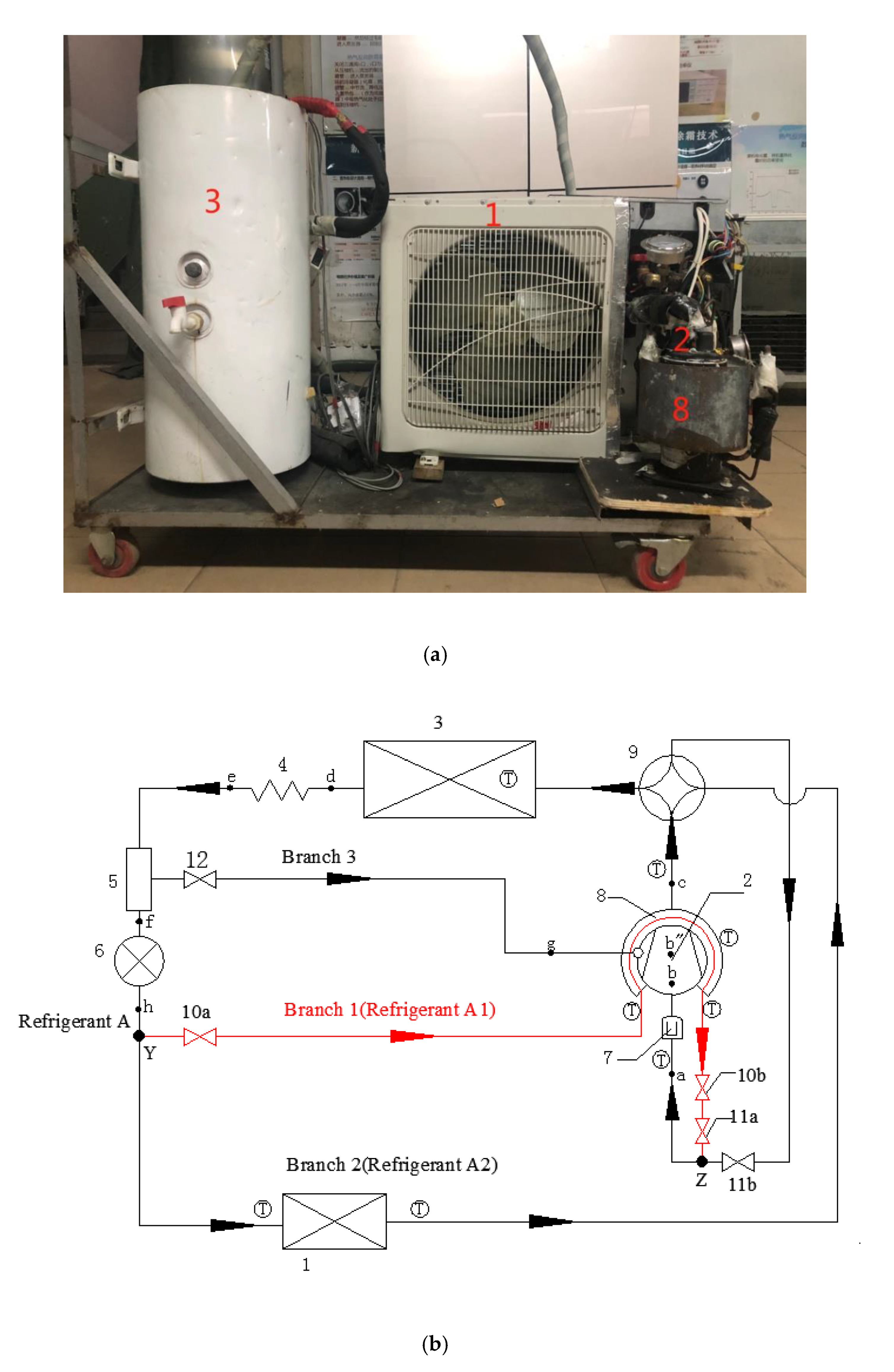
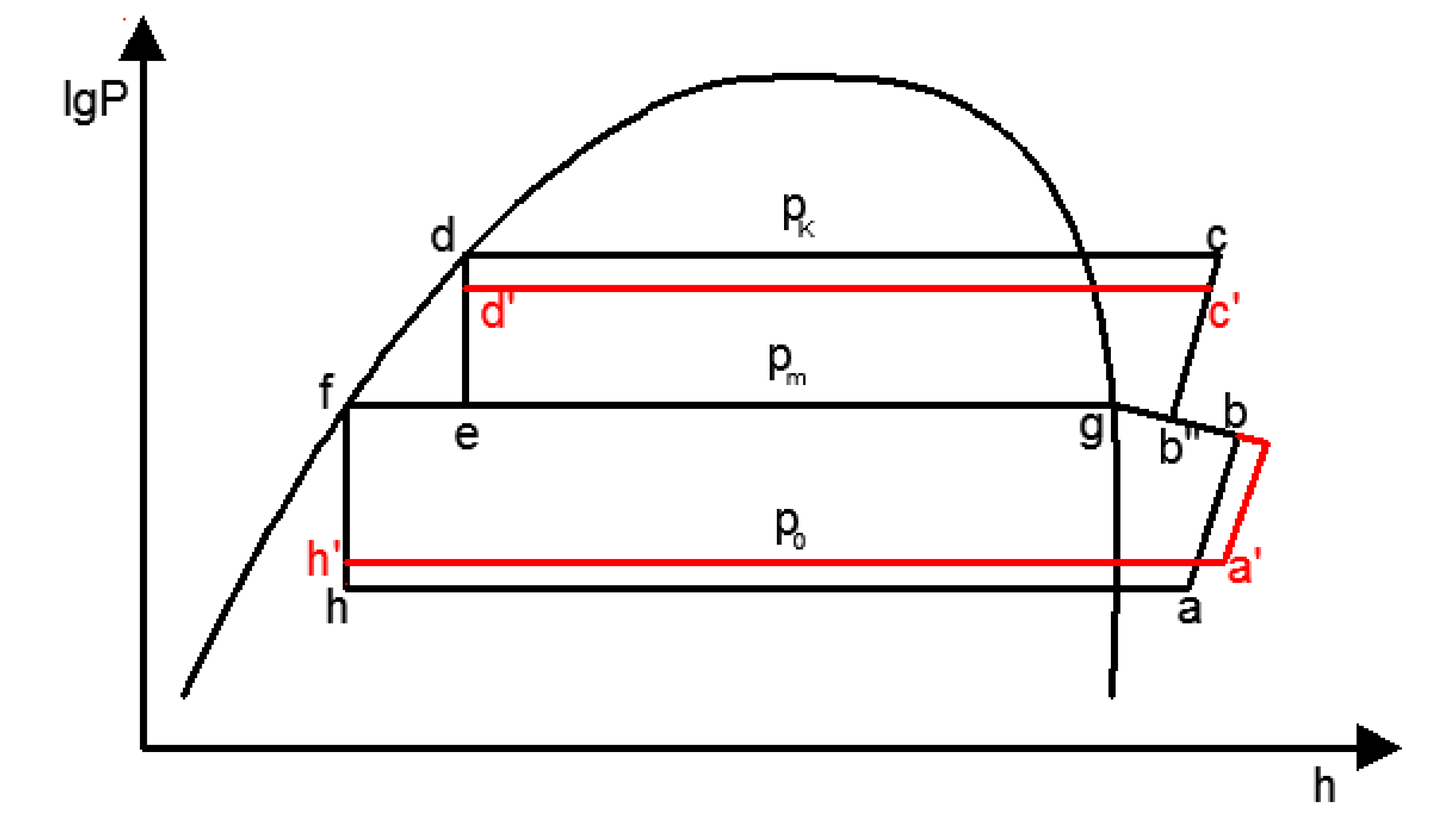
The actual image, flow chart and pressure-enthalpy diagram of the original system and proposed DE-CCTS are shown in Figure 1 and Figure 2, respectively. When the system is performing a heating cycle at a low temperature, the high-temperature and high-pressure vapor at point a discharged from the compressor enter the indoor heat exchanger through the four-way reversing valve. The vapor then cools to a saturated liquid at point d and enters the flashtank to complete two-phase separation after being throttled to point e by the capillary. The vapor-injected supply circuit (Branch 3) opens on its own at a low temperature. Hence, the refrigerant vapor discharged from the flashtank enters the vapor-injected supply opening of the compressor, and the refrigerant liquid at point f discharged from the flashtank is throttled to point h by the electronic expansion valve (EEV). The gas–liquid mixture from the EEV enters Branches 1 and 2, which is called Refrigerant A. Refrigerant A starts to split at point Y and enters Branches 1 and 2, which is called Refrigerant A1 and Refrigerant A2, respectively. By opening and adjusting the opening degree of the manual control valve, Refrigerant A1 enters Branch 1, and the secondary evaporator is located on this branch. The thermal storage heat exchanger wrapped outside the compressor casing is used as a secondary evaporator to heat Refrigerant A1. Meanwhile, Refrigerant A2 enters Branch 2, and the main evaporator (outdoor heat exchanger) is located on this branch. In the end, Refrigerants A1 and A2 are mixed into the compressor suction port at point Z as superheated steam.

Figure 1.
Actual image and flow chart of the proposed dual evaporator combined with a compressor casing thermal storage heat pump system (DE-CCTS). 1. Main evaporator; 2. Compressor; 3. Water tank (with a condenser coil inside); 4. Capillary tube; 5. Flashtank; 6. Electronic expansion valve (EEV) 7. Gas–liquid separator; 8. Secondary evaporator; 9. Four-way reversing valve; 10. Manual control valve; 11. One-way valve; 12. Solenoid valve, (a) Actual image (b) Flow chart.

Figure 2.
Pressure-enthalpy diagram of the original system and proposed DE-CCTS.
The heat of compressor casing is used as a new auxiliary heat source, and its temperature is much higher than the ambient temperature, which is equivalent to the heat source of main evaporator. Theoretically, the suction and evaporation temperatures of the DE-CCTS are increased, so the suction and evaporation pressure are increased. In this manner, discharge temperature and pressure are decreased, and the heating capacity is increased. From the pressure-enthalpy diagram in Figure 2, it can be seen that h′-a′ and d′-c′ represent the suction and discharge pressure of the DE-CCTS, respectively. The suction pressure Po is higher than that of the original system, and the discharge pressure Pk is lower than that of the original system. At the same time, it can be seen that the compression ratio of the DE-CCTS is also reduced compared with that of the original system.
3. Experimental Apparatus and Method
3.1. Experimental Apparatus
3.1.1. DE-CCTS Device
As shown in Figure 1, DE-CCTS is based on a China Gree low-temperature ASHP water heater, whose model and operating refrigerant are KFRS-3.5JPd/NaA-1 and R410A, respectively. The main components of the proposed DE-CCTS are the compressor, water tank (with a condenser coil inside), flashtank, outdoor heat exchanger (main evaporator), and thermal storage heat exchanger (secondary evaporator). The rated power and maximum power of the compressor are 0.833 and 2 kW, respectively. The water tank is self-made with a total capacity of 50 L. It has an inner coiled pipe heat exchanger with a total length of 10 m that heats the water in the water tank. The main evaporator is a finned heat exchanger and the secondary evaporator is self-made.
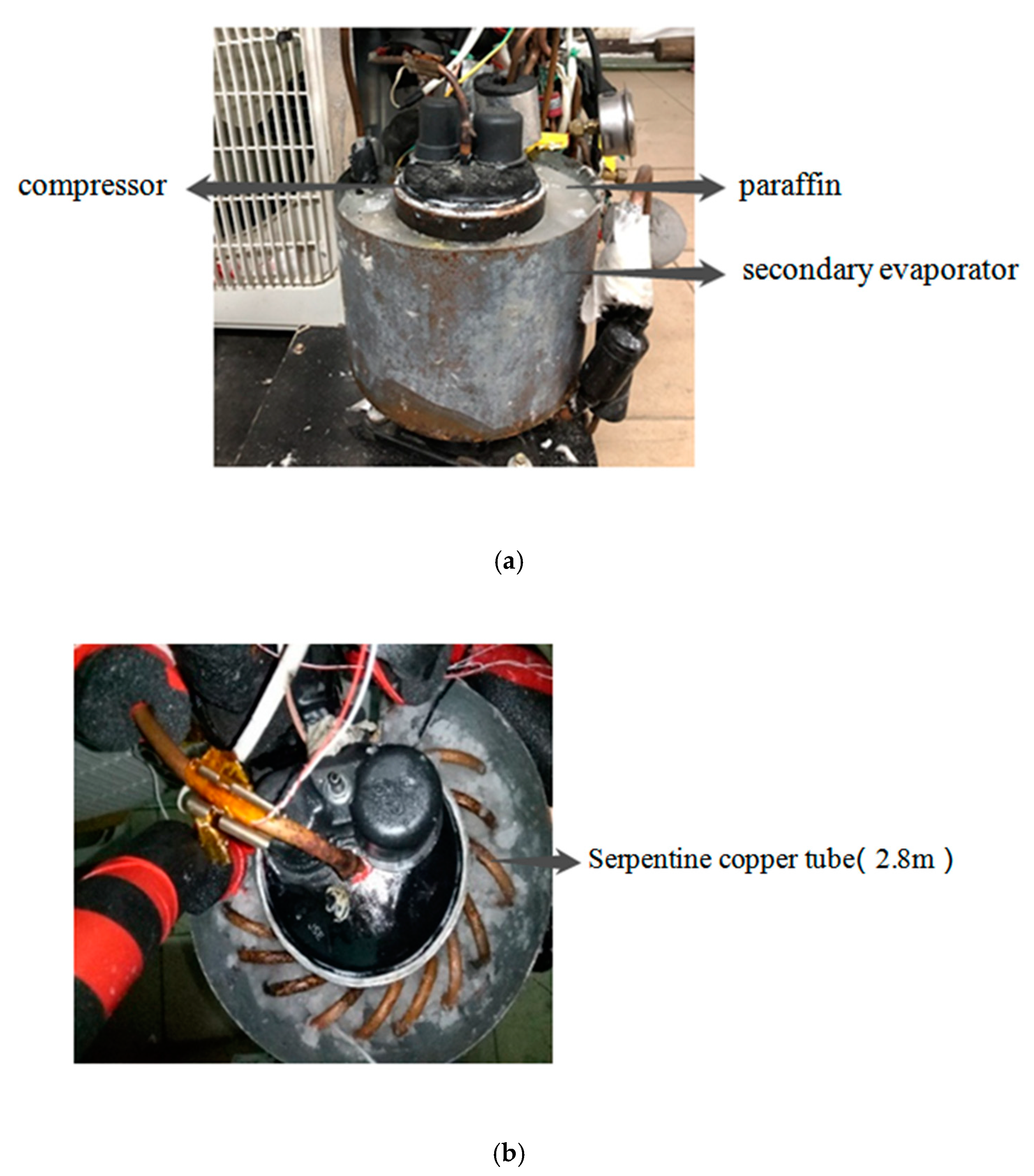
The secondary evaporator is the core part of this experiment, which is used to fill the PCM and complete the thermal storage and release operation between the PCM and the refrigerant in the heating cycle. Its size is determined in accordance with the mass of the thermal storage PCM and the shape of the compressor casing. As shown in Figure 3, the secondary evaporator is made into a hollow cylinder. The secondary evaporator is filled with 1.74 kg paraffin with phase change temperature of 45 °C, and the inner disc of paraffin has a diameter of 6 mm and a length of 2.8 m serpentine copper tube. The secondary evaporator is surrounded by a thin iron sheet to form a circular tank. Because the secondary evaporator needs to closely fit the compressor casing to absorb the waste heat, a layer of silica gel between the casing and the iron sheet is applied to enhance heat conduction. The experiment prototype is a 1.5 P compressor with height of 200 mm and diameter of 100 mm. According to the shape and size of the compressor, the inner diameter and outer diameter of the secondary evaporator are 100 mm and 180 mm, respectively, that is, the wall thickness of the secondary evaporator is 40 mm and the height is 150 mm.

Figure 3.
Secondary evaporator, (a) Filled PCM, (b) Half-filled PCM (exposed internal heat exchange tube).
3.1.2. Measuring Instrument and Measuring Point Layout
The experimental data required to be collected are the real-time changes in the values of parameters such as temperature, power, and humidity. The data are collected by automatic detection using Agilent 34,970, which is a multifunctional data acquisition instrument, and the data were collected, on average, once every 30 s. The measurement parameters and the instrument characteristics are shown in Table 1.

Table 1.
Measurement parameters and instrument characteristics.
The DE-CCTS has nine temperature measurement points, namely, the temperatures of the compressor suction and discharge ports, compressor casing, thermal storage PCM and water, and inlets and outlets of the main evaporator and secondary evaporator. Multiple temperature sensors are arranged, and the average value is taken after performing multiple tests to ensure the accuracy of the experiment. The arrangement of temperature measuring points is shown in Figure 1.
3.2. Experimental Method
All tests were in accordance with low ambient temperature air source heat pump (water chilling) packages—Part 2: Heat pump (water chilling) packages for household and similar applications of the China National standard [18], and were completed in the Environmental Simulation Laboratory in the Department of Refrigeration and Cryogenic Engineering of Beijing University of Technology.
The length and width of the laboratory were 2 m, and the height was 3 m. The wall was mainly insulated by rock wool board. The temperature and humidity were regulated in the following three ways, respectively: The heating method was a fin heating tube, the cooling method was an air-cooled refrigeration unit, and the humidification method was the water vapor heated by heating tube. The laboratory could simulate nine different ambient temperature conditions so that the outdoor temperature met the required experimental requirements, and the humidity requirements could also be achieved, namely, −25 °C; −18 °C; −12 °C, 30% RH; −6 °C, 50% RH; 0 °C, 40% RH; 7 °C, 90% RH; 15 °C; 25 °C; 35°C. When the outdoor temperature reached the condition, the indoor temperature was 25°C.
3.2.1. On-Time Mode of DE-CCTS and Performance Comparison
The DE-CCTS was tested under nine different ambient temperatures of −25 °C, −18 °C, −12 °C, −6 °C, 0 °C, 7 °C, 15 °C, 25 °C and 35 °C. The opening degree of the manual control valve (equivalent to adjusting the mass flow of Refrigerant A1) and the opening time of Branch 1 at these temperatures served as the focuses of this study. Multiple tests on the proposed DE-CCTS were performed at each ambient temperature. By constantly changing the opening degree of the manual control valve and the opening time of Branch 1, the suction and discharge temperatures, the rate of water temperature rise, and the COP of the DE-CCTS were compared to determine the optimal on-time mode under different ambient temperatures.
In the experiment performed under the nine ambient temperatures, the water in the water tank was controlled to ensure the same initial water temperature, water temperature rise, and mass of water. Under the premise of controlling the same heating capacity and optimal on-time mode, the suction and discharge temperatures, the rates of water temperature rise, and the COP values of the original system and the proposed DE-CCTS were compared. Under nine temperature conditions, the original system and the DE-CCTS all heat a tank of water of 50 L from 20 °C to 52 °C, that is to say, the heating capacity of two systems is the same, and the COP is determined by the power consumption. The calculation formula of COP is shown in (1), where M refers to a tank of water with a mass of 50 kg; C refers to the specific heat capacity of water of 4.2 kJ/(kg·°C); Δt refers to a water temperature rise of 32 °C; W refers to the integral of instantaneous power under each temperature condition, that is, the power consumption under each temperature condition.
M—Mass of the water in the water tank, kg, C—Specific heat capacity of water, kJ/(kg·°C), Δt—Water temperature rise, °C, W—Power consumption, kJ.
3.2.2. Uncertainty Analysis COP Value
Based on the mathematical model of synthesis uncertainty, the uncertainty of COP value is analyzed from the perspective of Type-A uncertainty and Type-B uncertainty. Type-A uncertainty analysis refers to that under each temperature condition, the experiment is carried out many times, and finally multiple COP values are taken. The DE-CCTS has been tested many times (six times) under each temperature condition. Under the premise that the data size and trend are basically the same with time under each temperature condition, these COP values are recorded as COP1, COP2, COP3, COP4, COP5 and COP6, respectively. In addition, the average of the six COP values is calculated according to formula (2) and recorded as COP’. Based on the statistical analysis method, the experimental standard deviation can be obtained, so the calculation formula of uncertainty of Type-A of the measured COP value are shown in (3).
Type-B uncertainty analysis means that the uncertainty is not obtained by repeated date acquisition of experiment, while the uncertainty is evaluated according to the uncertainty of measurement device. Temperatures are measured using Pt100 temperature transducers with an uncertainty of ±0.1 °C, and the power input to the compressor is measured using a power meter with an uncertainty of ±0.2%. During the test of heating COP, the C (specific heat capacity) and ρ (density) can be regarded as constants, and the COP is determined by three independent variables, namely tin (inlet temperature of water), tout (outlet temperature of water) and W (power consumption). Type-B uncertainty for the heating COP can be calculated with the follow Equation (4). The composite standard uncertainty of the heating COP can be obtained from the combination of Type-A uncertainty and Type-B uncertainty, and the calculation formula is shown in (5).
Since COP values are varied under different conditions, the range of standard relative errors are calculated according to the following formulas. The range of standard relative error under nine temperature conditions is 1.01–1.45%, and the maximum standard relative error of COP is 1.45%, so experimental COP value reliable enough.
4. Results and Discussion
4.1. Thermal Storage PCM
Phase change temperature, the type and mass of thermal storage PCM are the key issues explored in this study. Under the premise that the compressor is maximally insulated and the remaining volume outside the compressor is all occupied by the insulation cotton, the average temperature of the compressor casing is 58 °C when the compressor is continuously operated at low temperatures for multiple cycles. Hence, the phase change temperature of the thermal storage PCM should be lower than 58 °C.
In the phase change temperature range, inorganic materials are primarily crystalline water and salt materials, which have high thermal conductivity. However, during repeated phase changes, inorganic materials are prone to dehydration, which results in changes in their physical and chemical properties and reduced reliability. In this phase change temperature range, organic materials are mostly multicarbon organic matter. Such materials have good stability but low thermal conductivity and long duration of phase change. In the current study, the paraffin is used as thermal storage PCM. Liquid paraffin with a 17 °C phase change temperature is included in the PCM to reduce the phase change temperature and thereby make it suitable for the compressor casing temperature. The solid–liquid ratio of the paraffin is 6:4. The thermophysical parameters of the PCM according to Differential Scanning Calorimetry (DSC) are shown in Table 2. Calculating Formulas (6) and (7) yield a mixed paraffin mass of 1.45 kg.
Q—Heat released by the compressor casing during one cycle, kJ. α—Proportion of waste heat accounting for the total power of the compressor. P—Rated power of the compressor, kW. t—Maximum time for a running cycle of the compressor, s.
m—Mass of thermal storage PCM, kg. γ—Latent heat of thermal storage PCM, kJ/kg.

Table 2.
Thermal properties of the phase change material.
4.2. On-Time Mode of DE-CCTS under Different Ambient Temperatures
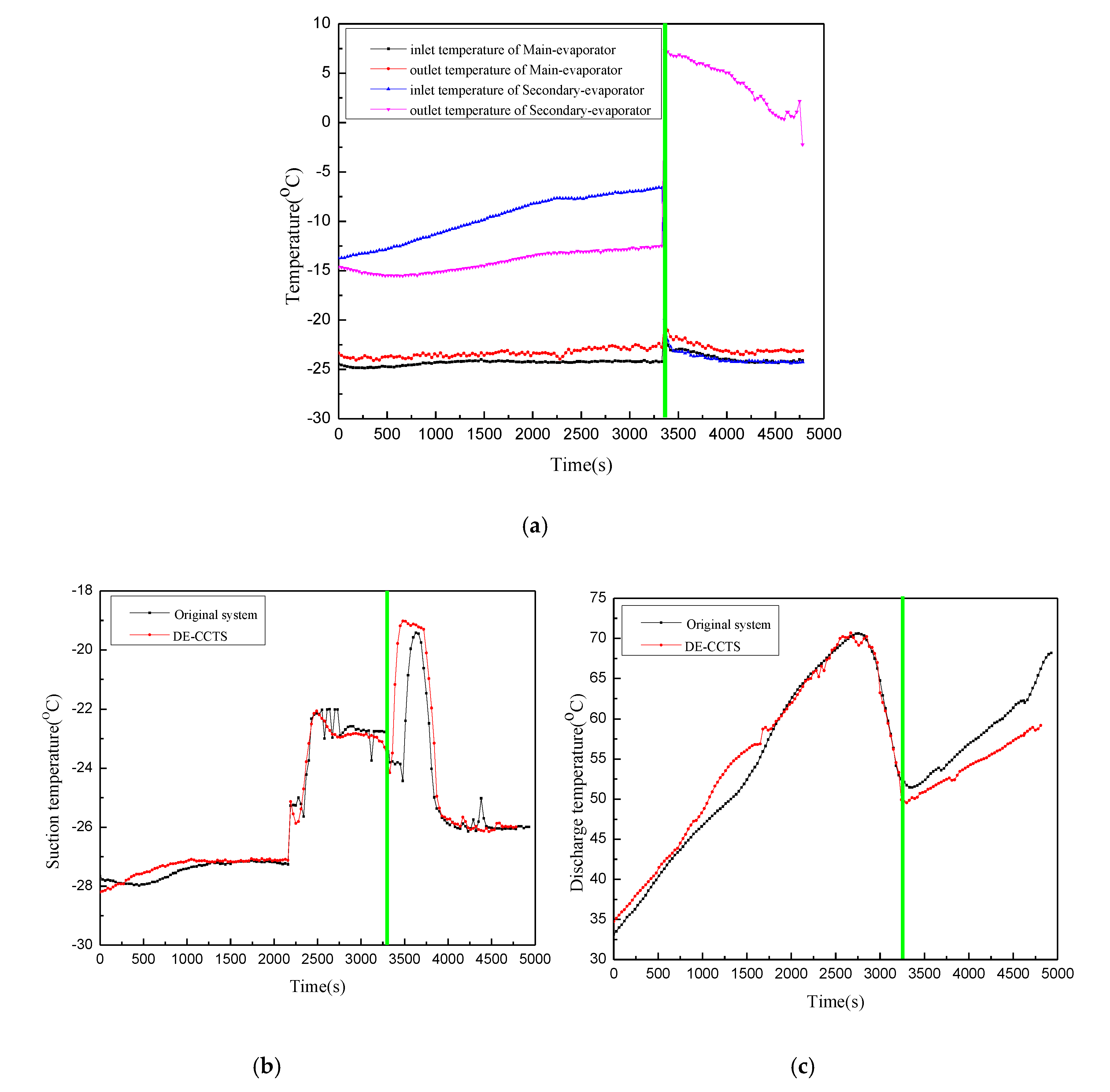
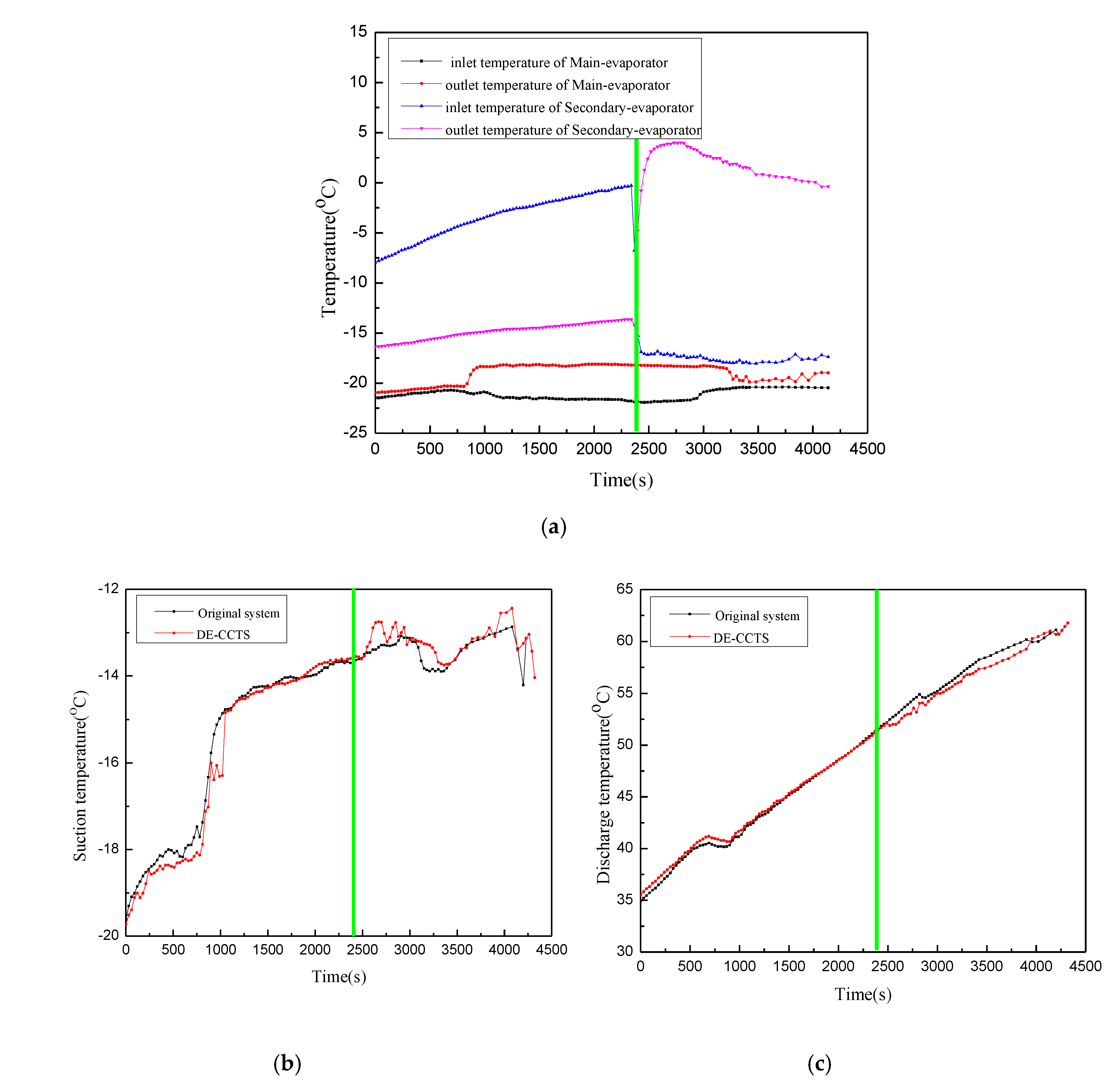
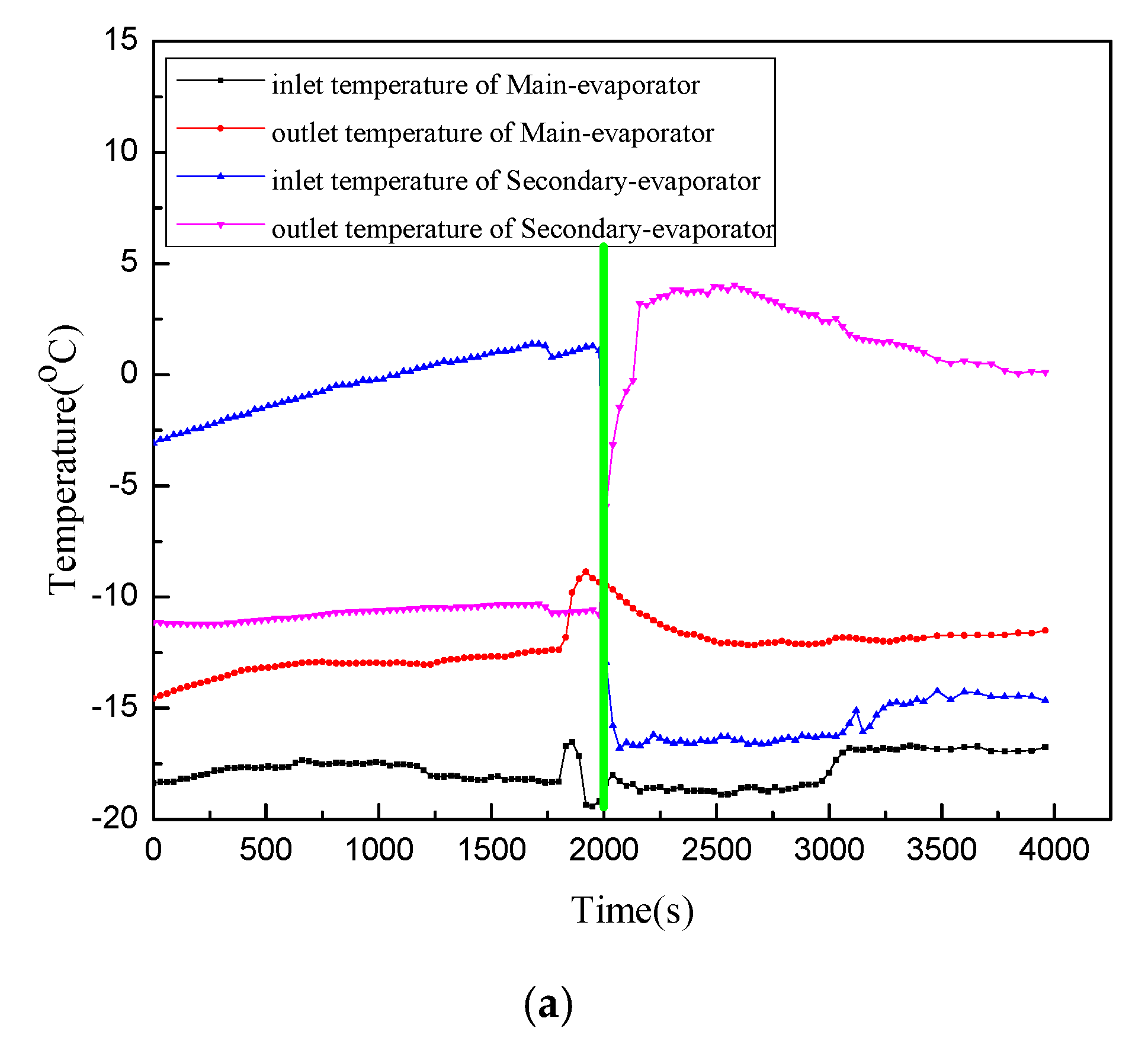
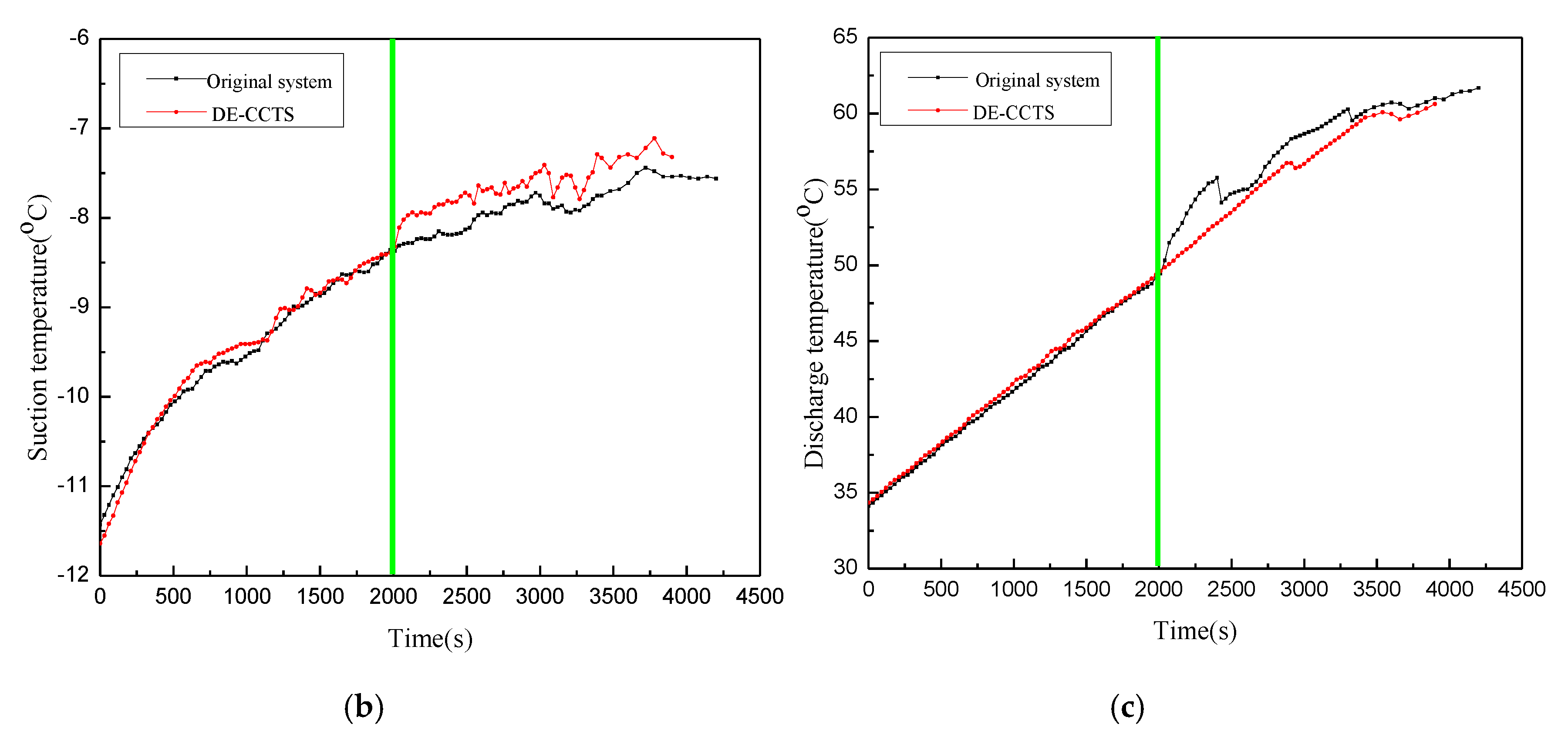
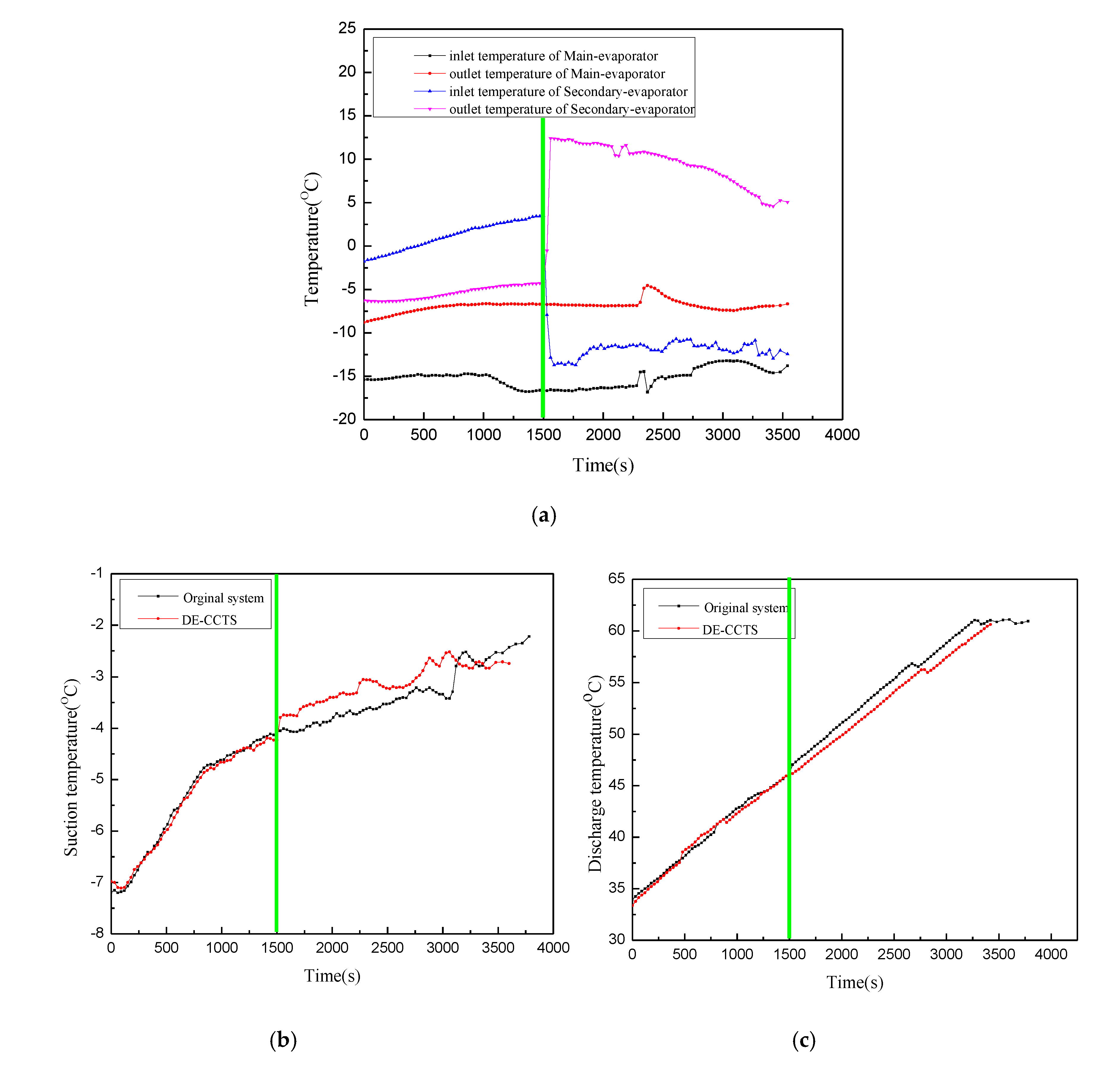
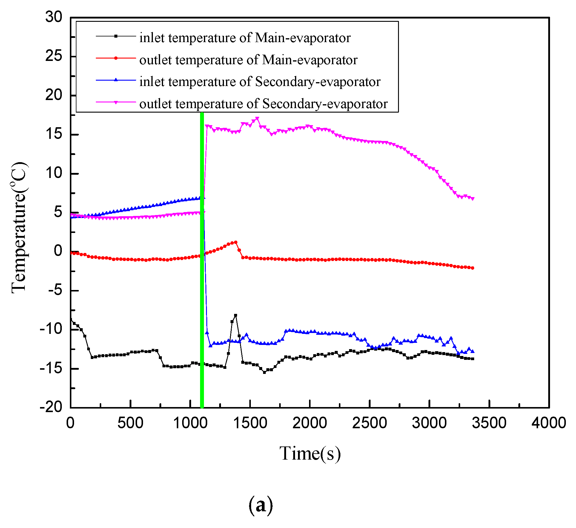
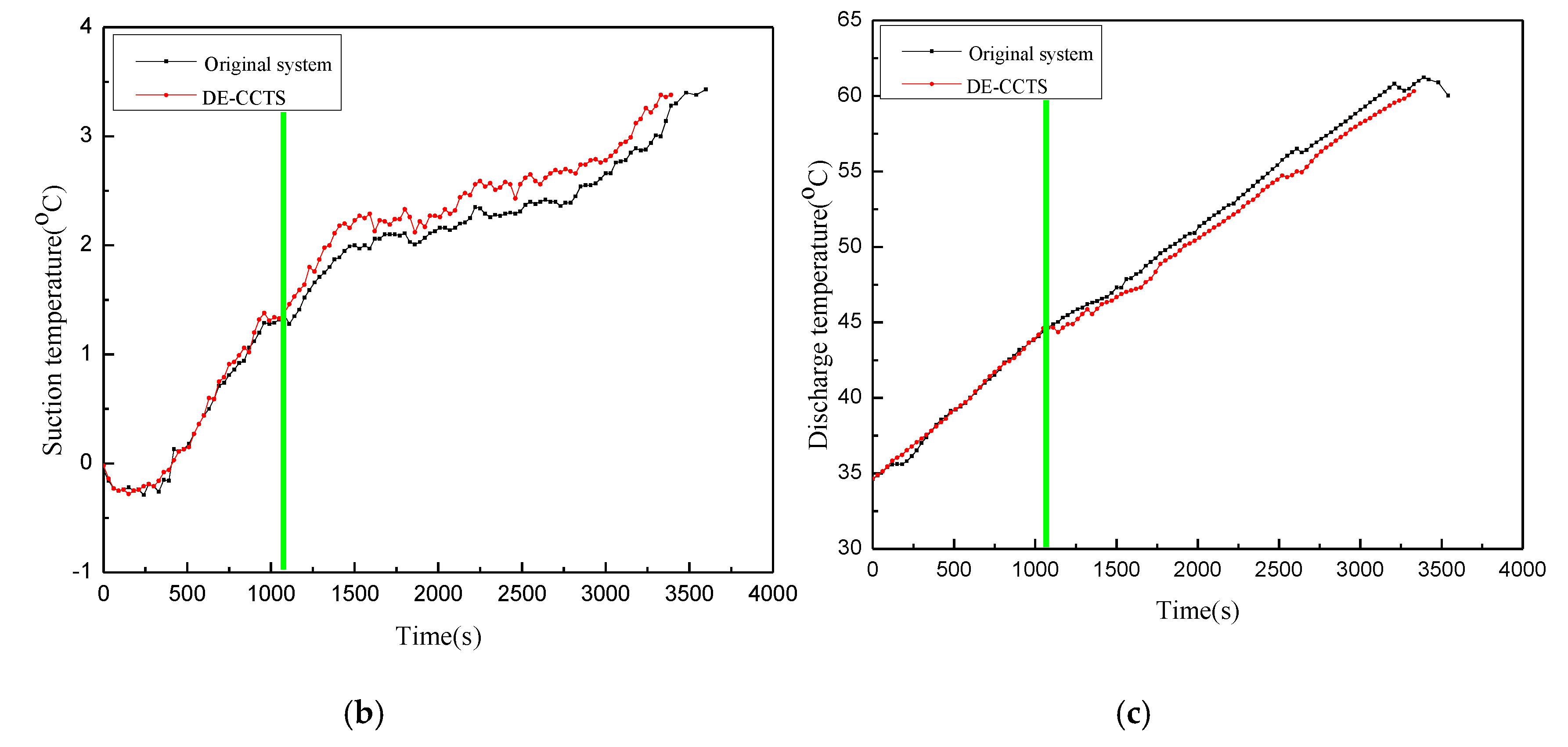
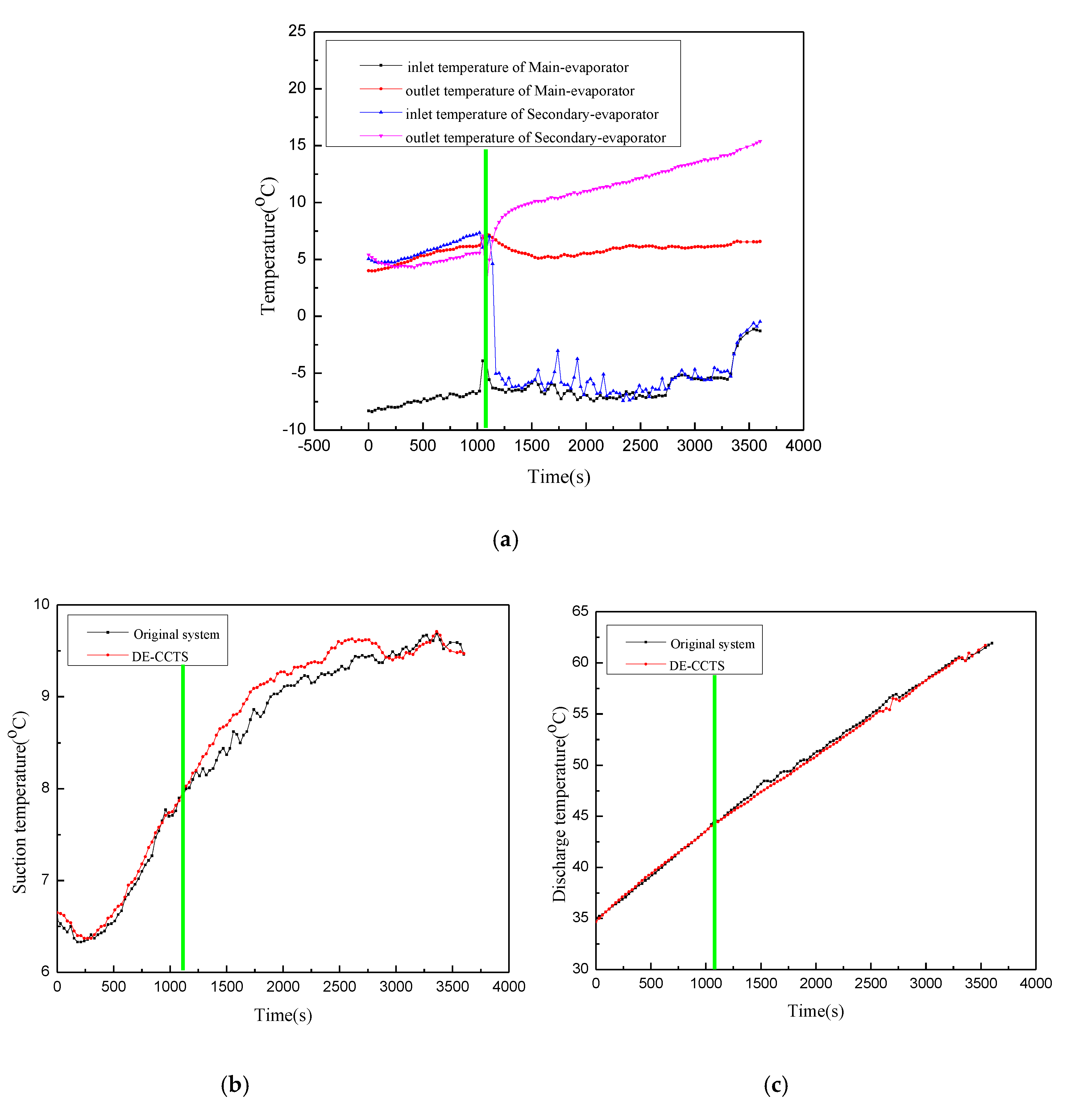
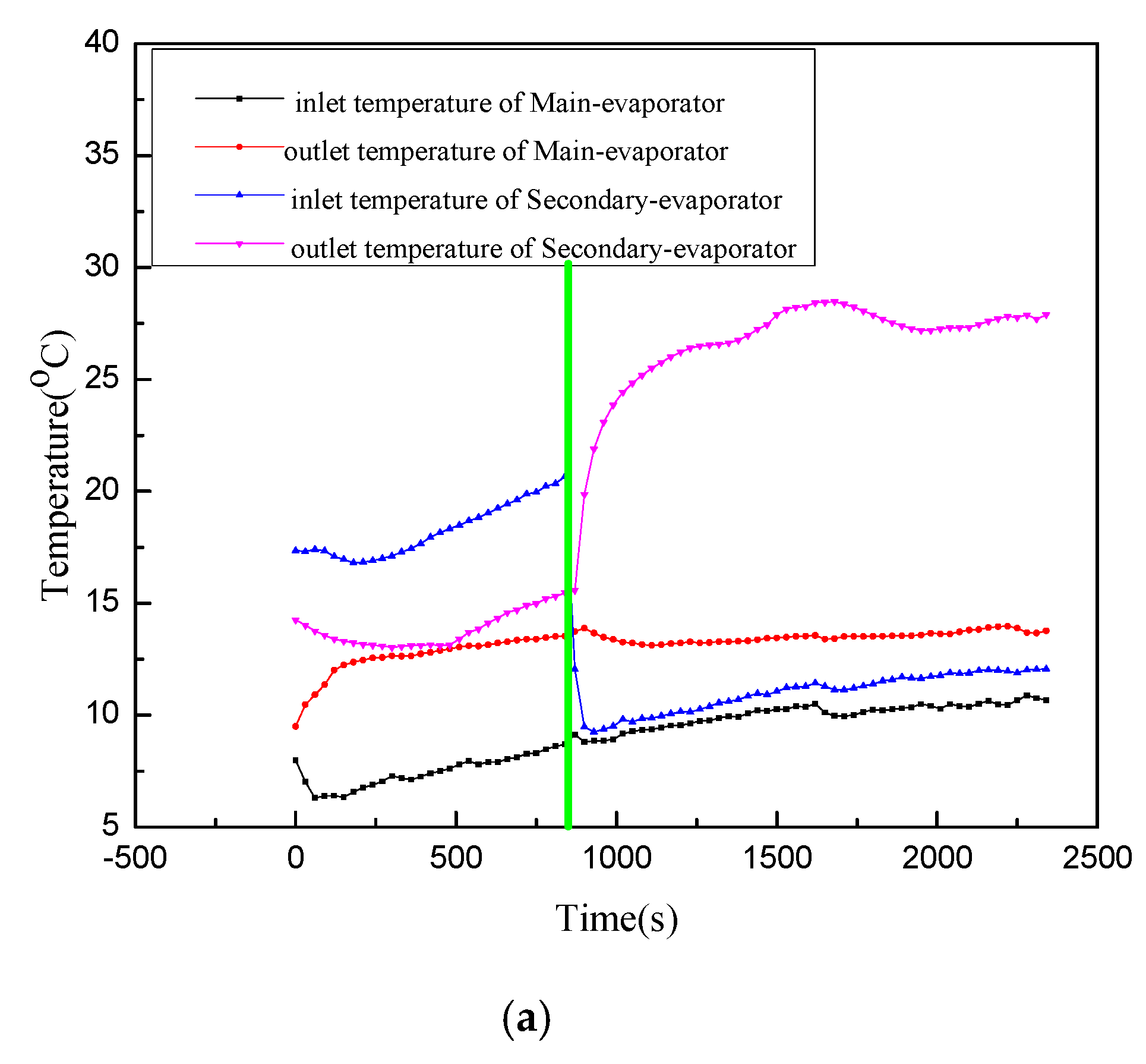
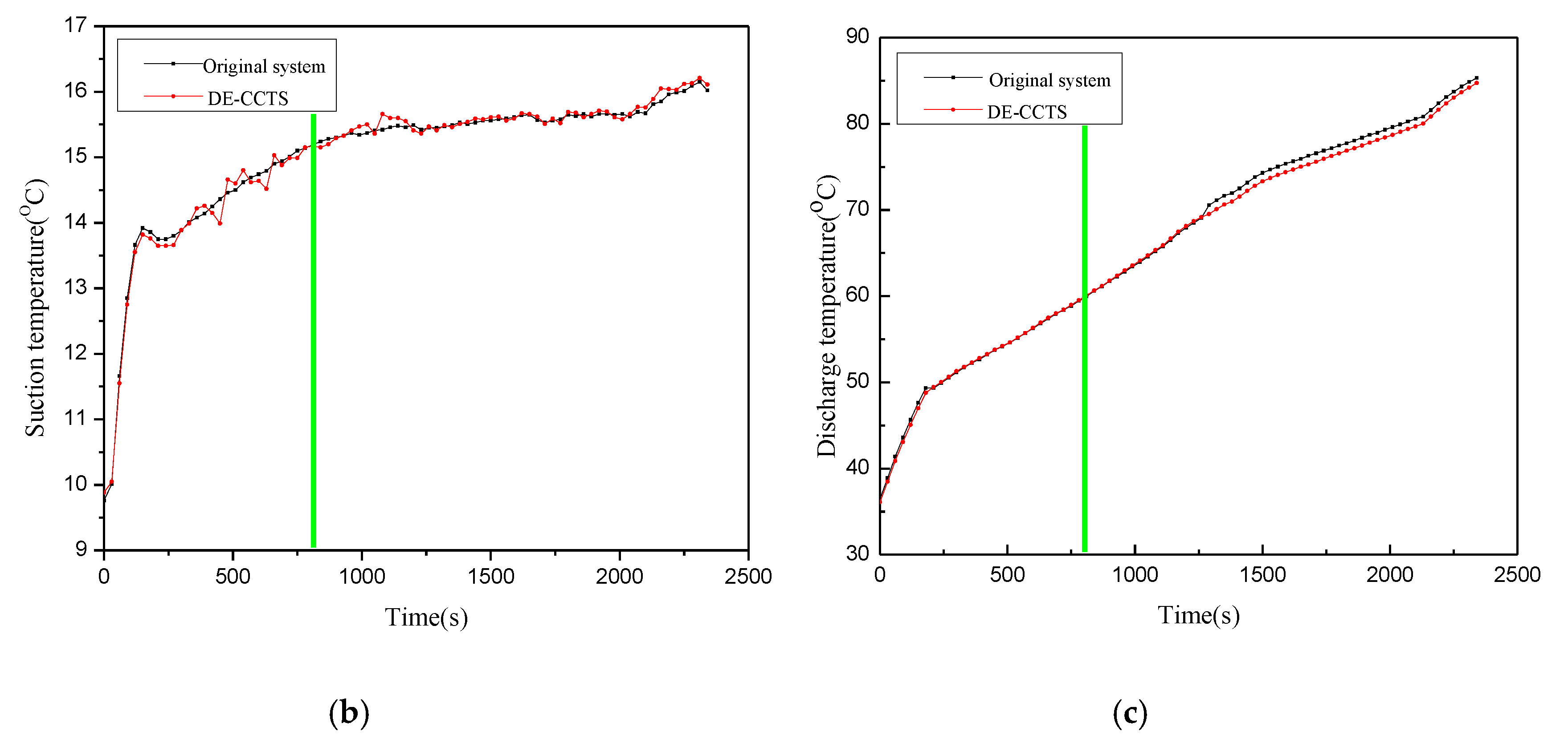
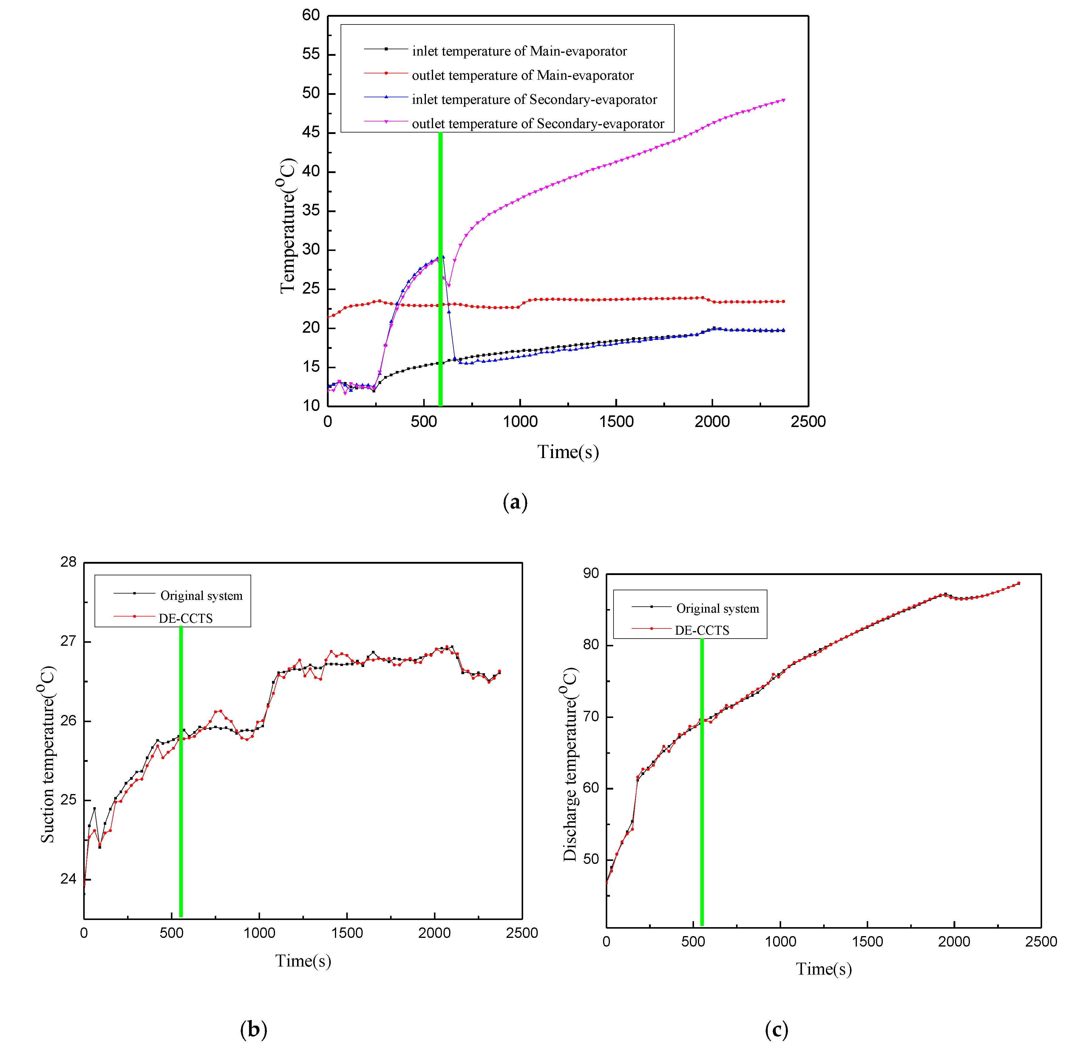
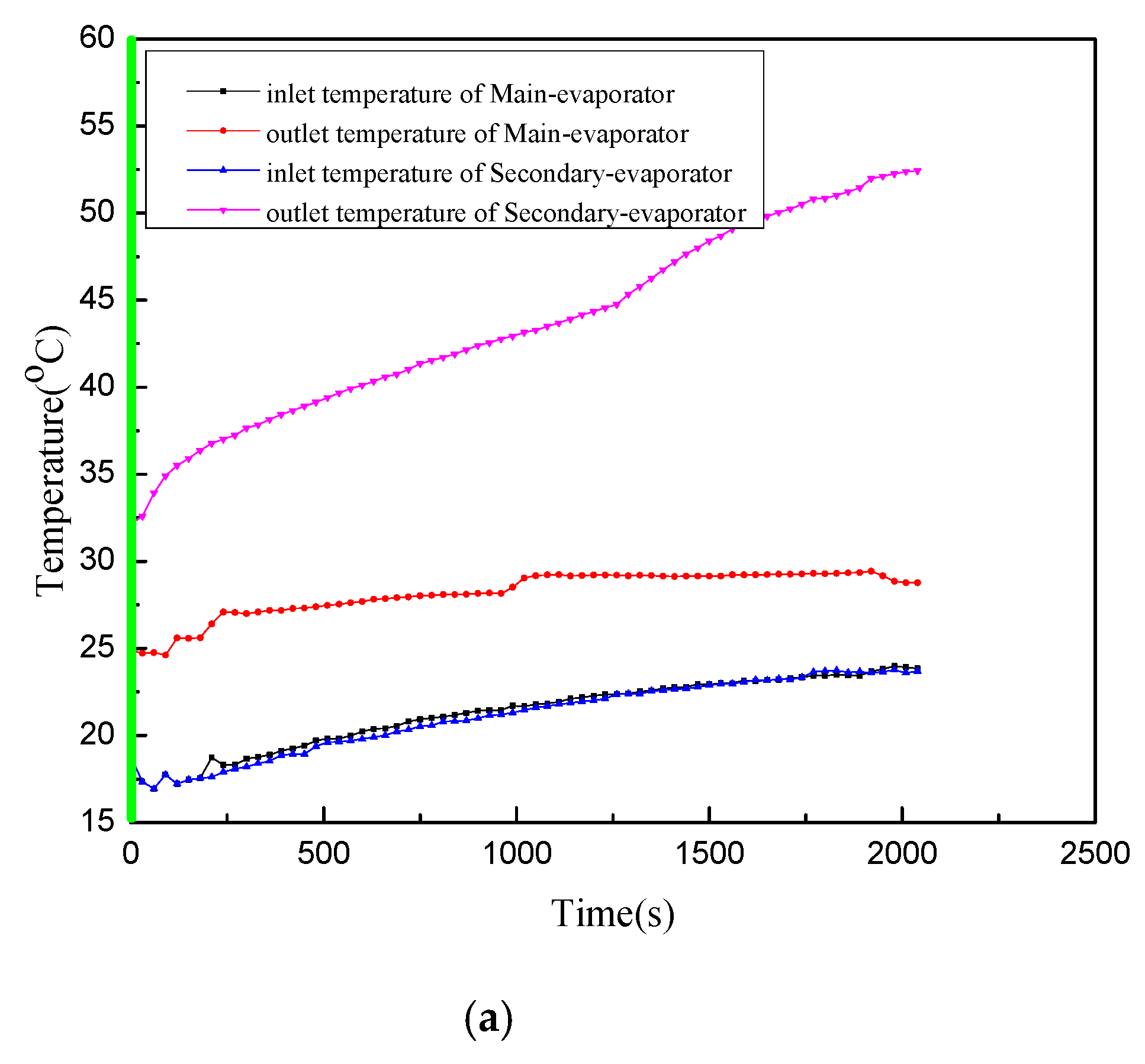
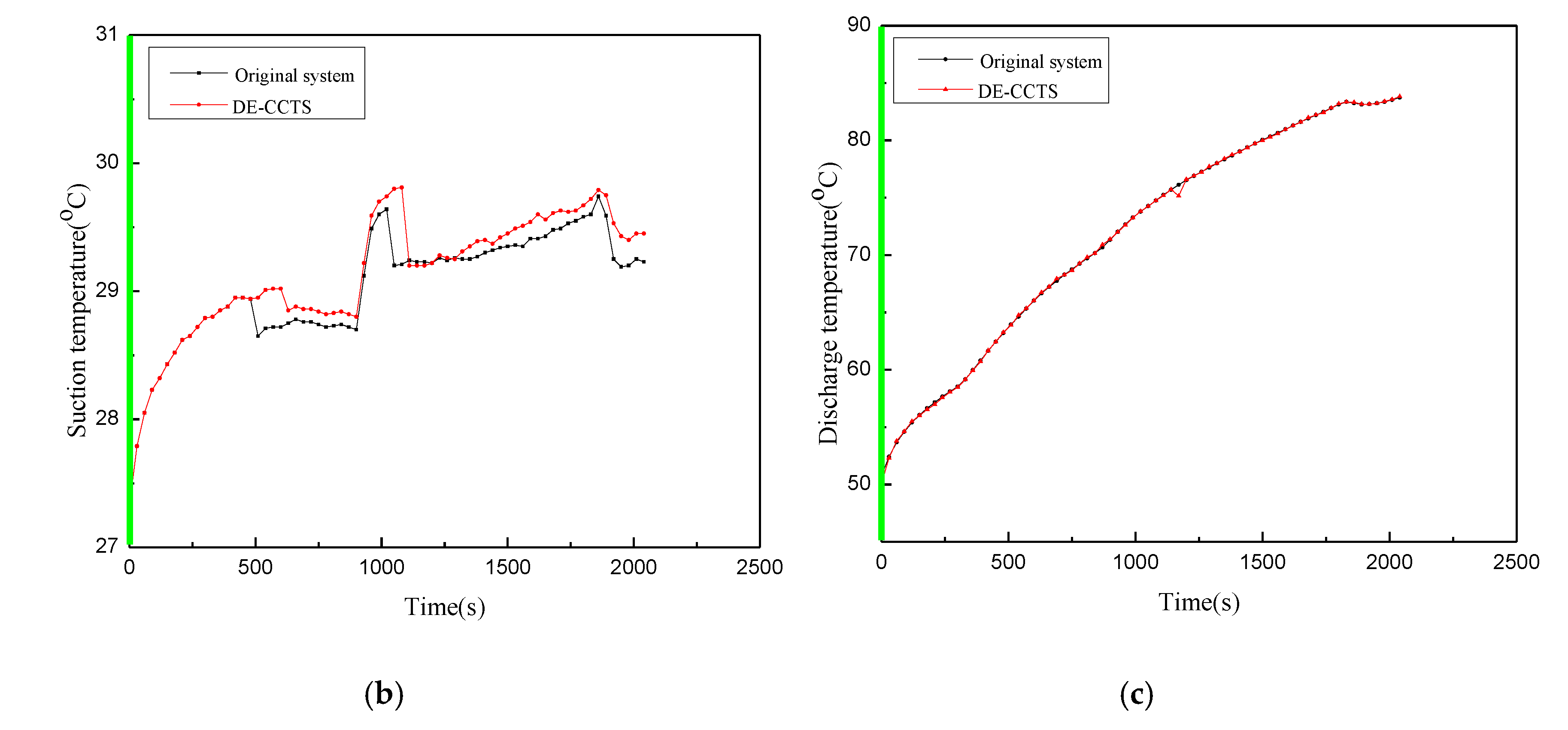
Figure 4a, Figure 5a, Figure 6a, Figure 7a, Figure 8a, Figure 9a, Figure 10a, Figure 11a and Figure 12a show the inlet and outlet temperatures of the main evaporator and secondary evaporator under nine ambient temperatures; here, the mass of Refrigerant A1 and the opening time of Branch 1 are different. The mass flow of Refrigerant A1 is small. As a result, the mass flow meter does not work so that Refrigerant A1 cannot be measured. After several tests, the opening degree of the manual control valve is based on the inlet and outlet temperatures of the secondary evaporator. According to the trend of the inlet and outlet temperatures of the secondary evaporator, the following nine temperature conditions are divided into two parts for analysis: the first opening mode is at −25 °C, −18 °C, −12 °C, −6 °C and 0 °C, the second opening mode is at 7 °C, 15 °C, 25 °C and 35 °C. In Figure 4, Figure 5, Figure 6, Figure 7, Figure 8, Figure 9, Figure 10, Figure 11 and Figure 12, the green vertical line represents the opening of Branch 1, which means that the secondary evaporator starts to work.

Figure 4.
Temperature chart for −25 °C, (a) Inlet and outlet temperatures of the main and secondary evaporators of the proposed DE-CCTS, (b) Suction temperature, (c) Discharge temperature.

Figure 5.
Temperature chart for −18 °C, (a) Inlet and outlet temperatures of the main and secondary evaporators of the proposed DE-CCTS, (b) Suction temperature, (c) Discharge temperature.

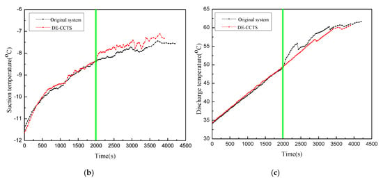
Figure 6.
Temperature chart for −12 °C, (a) Inlet and outlet temperatures of the main and secondary evaporators of the proposed DE-CCTS, (b) Suction temperature, (c) Discharge temperature.

Figure 7.
Temperature chart for −6 °C, (a) Inlet and outlet temperatures of the main and secondary evaporators of the proposed DE-CCTS, (b) Suction temperature, (c) Discharge temperature.

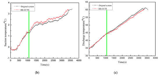
Figure 8.
Temperature chart for 0 °C, (a) Inlet and outlet temperatures of the main and secondary evaporators of the proposed DE-CCTS, (b) Suction temperature, (c) Discharge temperature.

Figure 9.
Temperature chart for 7 °C, (a) Inlet and outlet temperatures of the main and secondary evaporators of the proposed DE-CCTS, (b) Suction temperature, (c) Discharge temperature.

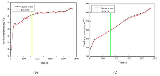
Figure 10.
Temperature chart for 15 °C, (a) Inlet and outlet temperatures of the main and secondary evaporators of the proposed DE-CCTS, (b) Suction temperature, (c) Discharge temperature.
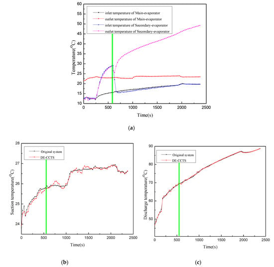
Figure 11.
Temperature chart for 25 °C, (a) Inlet and outlet temperatures of the main and secondary evaporators of the proposed DE-CCTS, (b) Suction temperature, (c) Discharge temperature.

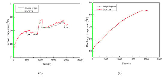
Figure 12.
Temperature chart for 35 °C, (a) Inlet and outlet temperatures of the main and secondary evaporators of the proposed DE-CCTS, (b) Suction temperature, (c) Discharge temperature.
Firstly, the inlet and outlet temperatures of the two evaporators at a low temperature were introduced. At −25 °C, −18 °C, −12 °C, −6 °C and 0 °C, with the increase of temperature, the proportion of the opening time of Branch 1 to the total time is 33%, 42.9%, 54.4%, 58.3% and 60.3%, respectively. When the Branch 1 is not opened, the inlet and outlet temperatures of the secondary evaporator are significantly higher than those of the main evaporator, and the inlet and outlet temperatures of the secondary evaporator keep increasing. This stage is defined as the first stage of DE-CCTS at a low temperature. At the end of the first stage, the manual control valve is opened and the opening degree of the two valves is adjusted. The opening degree is adjusted according to the inlet and outlet temperatures of the Refrigerant A1. When the valve is adjusted to the optimal opening degree, the inlet temperature of the secondary evaporator drops rapidly but is still higher than that of the main evaporator, and the outlet temperature of the secondary evaporator suddenly rises to a maximum value and then decreases. This stage is defined as the second stage of DE-CCTS at low temperature.
Secondly, inlet and outlet temperatures of the two evaporators at medium-high temperatures were introduced. At 7 °C, 15 °C, 25 °C and 35 °C, with the increase of temperature, the proportion of the opening time of Branch 1 to the total time is 63.6%, 65.9%, 74.4% and 100%, respectively. When the Branch 1 is not opened, temperature trend is basically the same as that at low temperature. This stage is defined as the first stage of DE-CCTS at medium-high temperatures. At the end of the first stage, when the valve is adjusted to the optimal opening degree, the inlet temperature of the secondary evaporator drops rapidly but is still higher than that of the main evaporator, and the outlet temperature of the secondary evaporator slowly rises. This stage is defined as the second stage of DE-CCTS at medium-high temperatures.
4.3. Summary of the Law of on-Time Mode
The total time required for heating 50 L water in the water tank from 20°C to 52°C and the opening time of Branch 1 under nine temperature conditions are shown in Table 3. It can be seen from Table 3 that as the temperature increases, the proportion of the opening time of Branch 1 to the total time increases gradually. As the ambient temperature gradually increases, the heat stored in the secondary evaporator is more and more, so the opening time of the Branch 1 is longer and longer, but at the same time, the opening degree of the manual control valve is another important factor.

Table 3.
Opening time of Branch 1 under nine ambient temperature.
The opening degree of manual control valve at nine ambient temperatures is different, and the mass flow of Refrigerant A1 is too small to be measured, so the abstract method of the inlet and outlet temperatures of the main evaporator and the secondary evaporator is used to determine the optimal opening degree of the DE-CCTS. With the increase of temperature, the opening degree of the manual control valve is smaller and smaller. Since the opening time is extended, in order to avoid Refrigerant A1 quickly taking away the heat stored in the secondary evaporator, the mass flow of Refrigerant A1 should not be too large, and the opening degree of valve is relatively small.
In the first stage of the nine temperature conditions, the reason why the inlet and outlet temperatures of the secondary evaporator of the DE-CCTS is relatively high is that the Branch 1 is not opened, at this time, the secondary evaporator is in the thermal storage stage, and the heat absorbed by the PCM is more and more, so the temperature of the copper tube immersed in the PCM is higher and higher. The reason why the outlet temperature trend of the secondary evaporator of DE-CCTS is different at low and medium-high temperature is that the opening degree of valve at medium-high temperature is smaller than that at low temperature, so the mass flow of Refrigerant A1 is relatively small, and Refrigerant A1 slowly absorbs the heat stored by PCM, so the outlet temperature of the secondary evaporator rises slowly. In the case of low temperature, the opening degree of manual control valve is larger than that of medium-high temperature, so when the Branch 1 is opened, the mass flow of refrigerant A1 is larger, and Refrigerant A1 quickly absorbs the heat stored by PCM, and then the outlet temperature drops slowly.
4.4. Performance Comparison between Original System and DE-CCTS
Figure 4b,c, Figure 5b,c, Figure 6b,c, Figure 7b,c, Figure 8b,c, Figure 9b,c, Figure 10b,c, Figure 11b,c and Figure 12b,c show the suction and discharge temperatures of the original system and the proposed DE-CCTS, respectively. At −25 °C, −18 °C, −12 °C, −6 °C, 0 °C and 7 °C, the suction temperature increases, and the discharge temperature decreases when the secondary evaporator is opened. Under these six ambient temperatures, the rate of water temperature rise in the DE-CCTS is improved relative to that of the original system. At 15 °C and 25 °C, the suction temperature, the discharge temperature, and the rate of water temperature rise of the proposed DE-CCTS do not change when the secondary evaporator is opened. Relative to that of the original system at 35 °C, the suction temperature of the proposed DE-CCTS increases. The COP values of the original system and the DE-CCTS and the percentage of COP increase are shown in Table 4. Theoretically, as the temperature decreases, the increase rate of the COP values will increase. The proposed DE-CCTS is not effective at −18 °C and −25 °C because minimal heat is accumulated at low temperatures.

Table 4.
COP values under nine ambient temperature.
By comparing the temperature values of the original system and the proposed DE-CCTS, the cause of this phenomenon is theoretically analyze using the lgP-h diagram. Figure 2 presents the lgP-h diagrams of the original system and DE-CCTS when the vapor-injected supply circuit (Branch 3) is opened at a low temperature. Relative to the original system, the proposed DE-CCTS shows increased suction temperature and pressure and reduced compression ratio. Therefore, the discharge temperature, discharge pressure, and power consumption are all reduced. The ambient environment and the heat of the compressor casing are considered as the ambient heat sources of the main and secondary evaporators, respectively. The temperature of the compressor casing is relatively high. Thus, the temperature of the mixed refrigerant from both evaporators rises, that is, the suction temperature increases. Therefore, the effects of the secondary evaporator are evident when the ambient temperature is low. Theoretically, the rate of increase of the COP rises as the ambient temperature decreases. When the proposed DE-CCTS is at −18 °C and −25 °C, the COP drops rapidly because the ambient temperature is excessively low, thereby causing minimal heat accumulation in the paraffin.
By testing the performance of the system under nine constant temperature conditions, we can analyze the performance changes of the system based on the daily temperature changes in Beijing, the capital of China in winter. In the winter of Beijing, the temperature can reach −12 °C in the morning, and then slowly rises to −6 °C. The maximum temperature can reach 0 °C at about two o’clock in the afternoon and drops to −12 °C at night. We can see that the increase rate of COP value is the largest at −12 °C and the smallest at 0 °C, which is fully consistent with the increase rate of COP values of the system under nine temperature conditions.
In addition, it should be mentioned that the secondary evaporator had the effect of reducing compressor noise. Under the premise that the indoor and outdoor temperatures were set at 25 °C, the experiments of measuring the compressor noise were measured in the quiet environment. First, the background noise was measured in the laboratory, and the average noise value of 37.2 dB was taken. Secondly, the experiments of original system were carried out, that is, there was no package of the second evaporator outside the compressor. The experiment measured a group of data every 5 minutes for 1 h. The average compressor noise value was 58.9 dB, which was the working noise of exposed compressor. Finally, under the same conditions, the experiment of DE-CCTS was carried out, taking the average noise value as 49.7 dB, which is the working noise of the compressor wrapped by the secondary evaporator. Compared with the two systems, the DE-CCTS could reduce noise by 15.6%, which showed that the secondary evaporator had a significant effect on noise reduction.
5. Conclusions
Experimental research using a China Gree low-temperature ASHP water heater with EVI was conducted. The conclusions are as follows:
- (1)
- The proposed DE-CCTS uses thermal storage PCM, which is filled in the secondary evaporator, to recover the waste heat of the compressor casing. The waste heat of the compressor casing is considered a high-temperature ambient environment of the secondary evaporator. It increases the suction temperature and decreases the discharge temperature, especially at low temperatures.
- (2)
- Relative to the original system under different ambient temperatures, the proposed DE-CCTS shows a 0.1–1°C increase in suction temperature, a 0.1–0.5 °C decrease in discharge temperature, and 0.85–4.72% increase in the COP. These effects are especially evident at low temperatures.
Author Contributions
Conceptualization, Z.L. and F.L.; methodology, F.L.; validation, Z.L., F.L. and X.Q.; formal analysis, F.L.; investigation, Z.L.; resources, Y.S.; data curation, F.L.; writing—original draft preparation, F.L.; writing—review and editing, F.L.; visualization, Y.S.; supervision, Z.L.; project administration, F.L.; funding acquisition, X.Q. All authors have read and agreed to the published version of the manuscript.
Funding
This work is supported by the Beijing Natural Science Foundation (Grant No. 3202008), the National Natural Science Foundation of China (Grant No. 51776006) and Dezhou “Blue Fire” project of science and technology development center of Ministry of Education (Grant No. Q9005014201901).
Acknowledgments
Thanks to the laboratory of Environmental Energy college of Beijing university of technology for providing us with the necessary instruments.
Conflicts of Interest
The authors declare no conflict of interest.
References
- Zhang, L.; Jiang, Y.; Dong, J.; Yao, Y. Advances in vapor compression air source heat pump system in cold regions: A review. Renew. Sustain. Energy Rev. 2018, 8, 353–365. [Google Scholar] [CrossRef]
- Zheng, N.; Song, W.; Zhao, L. Theoretical and experimental investigations on the changing regularity of the extreme point of the temperature difference between zeotropic mixtures and heat transfer fluid. Energy 2013, 55, 541–552. [Google Scholar] [CrossRef]
- Zhang, Q.; Zhang, L.; Nie, J.; Li, Y. Techno-economic analysis of air source heat pump applied for space heating in northern China. Appl. Energy 2017, 207, 533–542. [Google Scholar] [CrossRef]
- Chen, J.; Havtun, H.; Palm, B. Conventional and advanced exergy analysis of an ejector refrigeration system. Appl. Energy 2015, 144, 139–151. [Google Scholar] [CrossRef]
- Kelly, J.A.; Fu, M.; Clinch, J.P. Residential home heating: The potential for air source heat pump technologies as an alternative to solid and liquid fuels. Energy Policy 2016, 98, 431–442. [Google Scholar] [CrossRef]
- Wang, B.; Ding, Y.; Shi, W. Experimental research on vapor-injected rotary compressor through end-plate injection structure with check valve. Int. J. Refrig. 2018, 96, 131–138. [Google Scholar] [CrossRef]
- Chen, J.; Yu, J. Energy and exergy analysis of a new direct-expansion solar assisted vapor injection heat pump cycle with subcooler for water heater. Sol. Energy 2018, 171, 613–620. [Google Scholar] [CrossRef]
- Xu, S.; Niu, J.; Cui, Z.; Ma, G. Experimental research on vapor-injected heat pump using injection subcooling. Appl. Therm. Eng. 2018, 136, 674–681. [Google Scholar] [CrossRef]
- Qi, H.; Liu, F.; Yu, J. Performance analysis of a novel hybrid vapor injection cycle with subcooler and flash tank for air-source heat pumps. Int. J. Refrig. 2017, 74, 540–549. [Google Scholar] [CrossRef]
- Wang, X.; Yu, J.; Xing, M. Performance analysis of a new ejector enhanced vapor injection heat pump cycle. Energy Convers. Manag. 2015, 100, 242–248. [Google Scholar] [CrossRef]
- Ooi, K.T.; Wong, T.N. A computer simulation of a rotary compressor for household refrigerators. Appl. Therm. Eng. 1997, 17, 65–78. [Google Scholar] [CrossRef]
- Park, Y.C. Transient analysis of a variable speed rotary compressor. Energy Convers. Manag. 2010, 51, 277–287. [Google Scholar] [CrossRef]
- Liu, Z.; Lou, F.; Qi, X.; Zhao, B.; Yan, J.; Shen, Y. Performance study of constant temperature water immersion thawing system using refrigerator compressor casing heat. Int. J. Energy Res. 2019, 1–12. [Google Scholar] [CrossRef]
- Liu, Z.; Fan, P.; Wang, Q.; Chi, Y.; Zhao, Z.; Chi, Y. Air source heat pump with water heater based on a bypass-cycle defrosting system using compressor casing thermal storage. Appl. Therm. Eng. 2018, 128, 1420–1429. [Google Scholar] [CrossRef]
- Liu, Z.; Zhao, F.; Zhang, L.; Zhang, R.; Yuan, M.; Chi, Y. Performance of bypass cycle defrosting system using compressor casing thermal storage for air-cooled household refrigerators. Appl. Therm. Eng. 2018, 130, 1215–1223. [Google Scholar] [CrossRef]
- Zhang, L.; Dong, J.; Jiang, Y.; Yao, Y. A novel defrosting method using heat energy dissipated by the compressor of an air source heat pump. Appl. Energy 2014, 133, 101–111. [Google Scholar]
- Huang, B.; Jian, Q.; Luo, L.; Zhao, J. Experimental study of enhancing heating performance of the air-source heat pump by using a novel heat recovery device designed for reusing the energy of the compressor shell. Energy Convers. Manag. 2017, 138, 38–44. [Google Scholar] [CrossRef]
- China National Standardization Management Committee. Low Ambient Temperature Air Source Heat Pump (Water Chilling) Packages—Part 2: Heat Pump (Water Chilling) Packages for Household and Similar Application; GB/T 25127.2-2010; China Standards Press: Shenzhen, China, 2010. (In Chinese) [Google Scholar]
© 2020 by the authors. Licensee MDPI, Basel, Switzerland. This article is an open access article distributed under the terms and conditions of the Creative Commons Attribution (CC BY) license (http://creativecommons.org/licenses/by/4.0/).

