A Novel Three-Phase Current Source Rectifier Based on an Asymmetrical Structure to Reduce Stress on Semiconductor Devices
Abstract
1. Introduction
2. Topological Structure
3. Basic Operation Principle and Stress Characteristics of the Proposed CSR
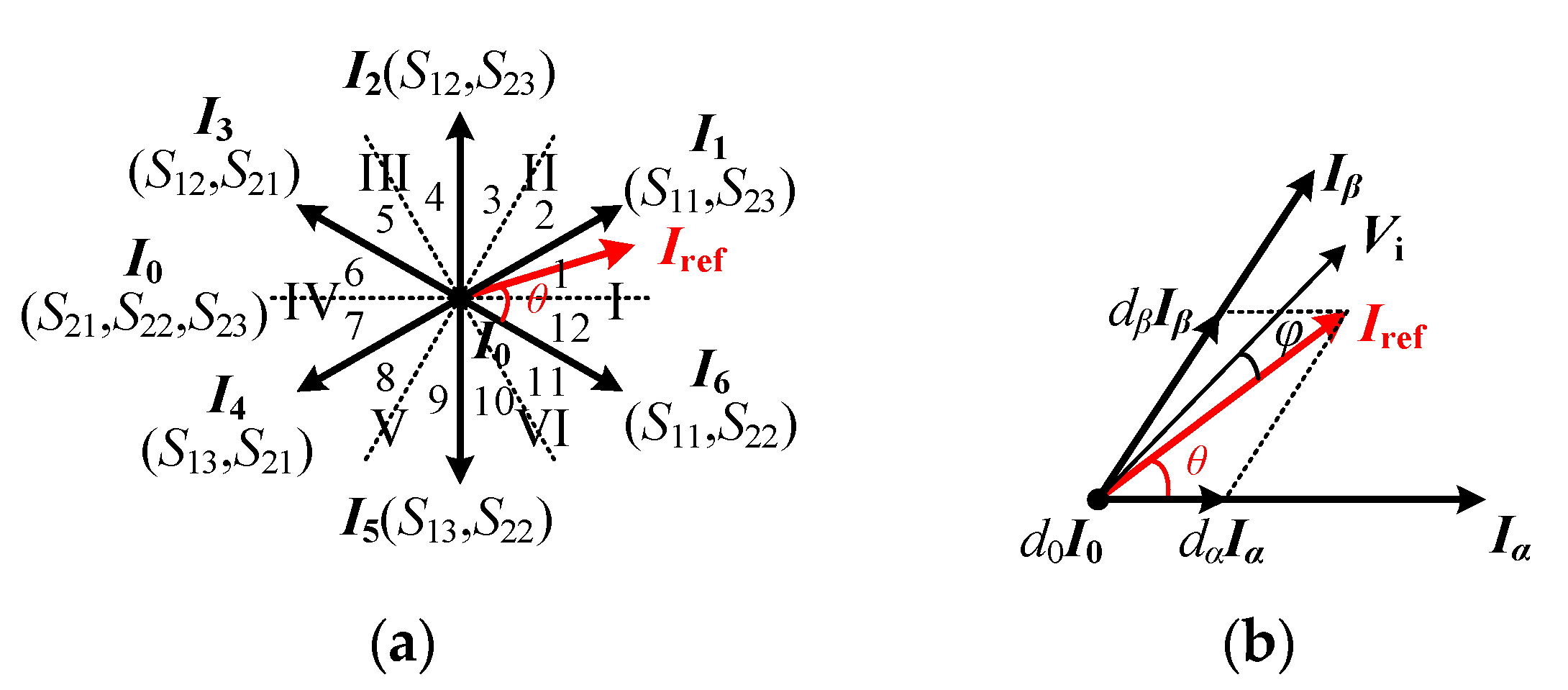
3.1. Modulation Scheme
3.2. Operation Modes
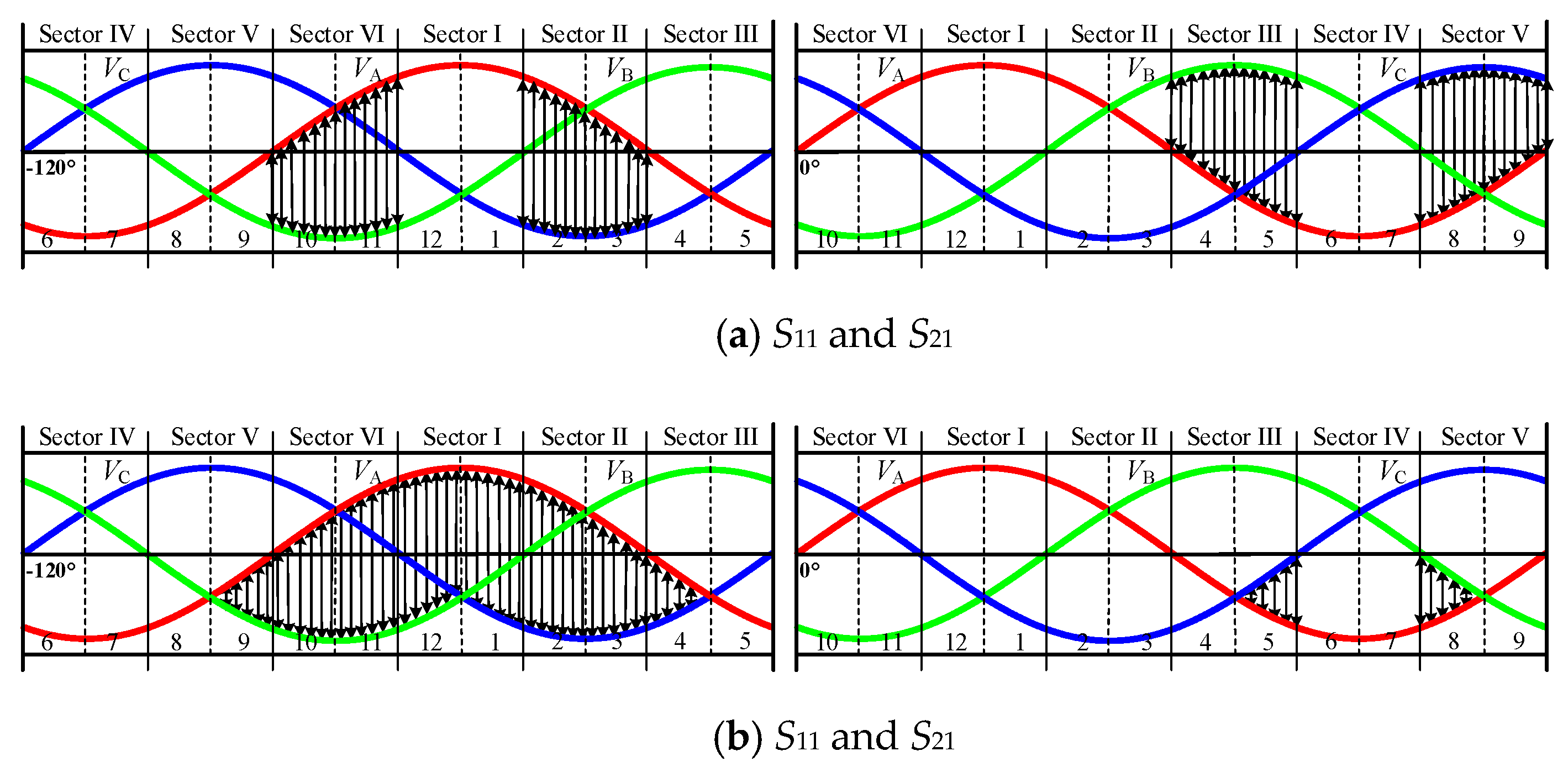
3.3. Voltage Stress
- (1)
- Upper arm: If Vx > VP (x = A, B, C), the transistors withstand the voltage stress Vx−VP, otherwise, the transistors withstand zero voltage stress.
- (2)
- Lower arm: If Vx > VN (x = A, B, C), the transistors withstand zero voltage stress, otherwise, the transistors withstand the voltage stress VN−Vx.
3.4. Current Stress
4. Discussions
4.1. Influence of Input Displacement Angle
4.2. Power Loss Analysis
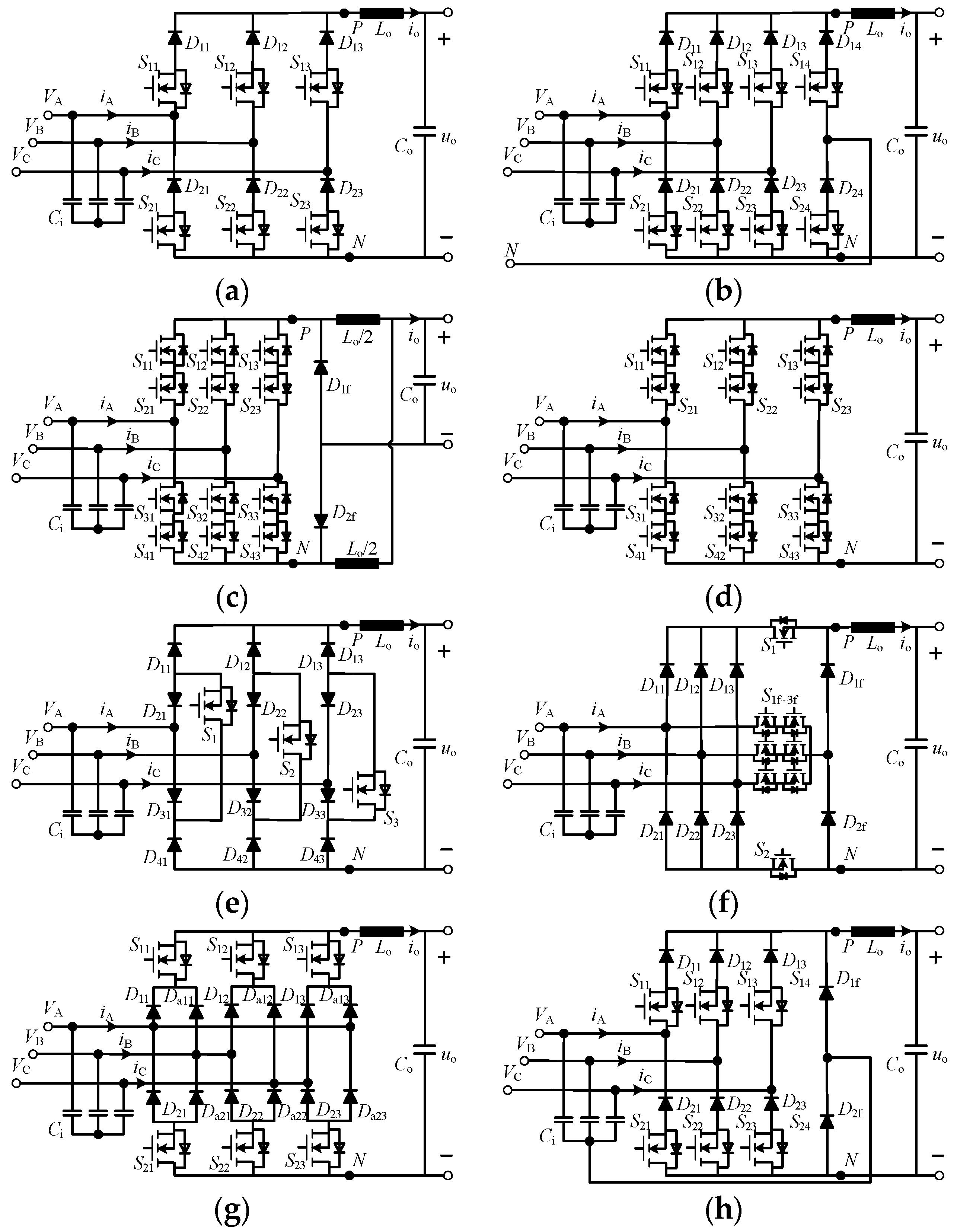
4.3. Comparative Analysis of Other Conventional CSRs
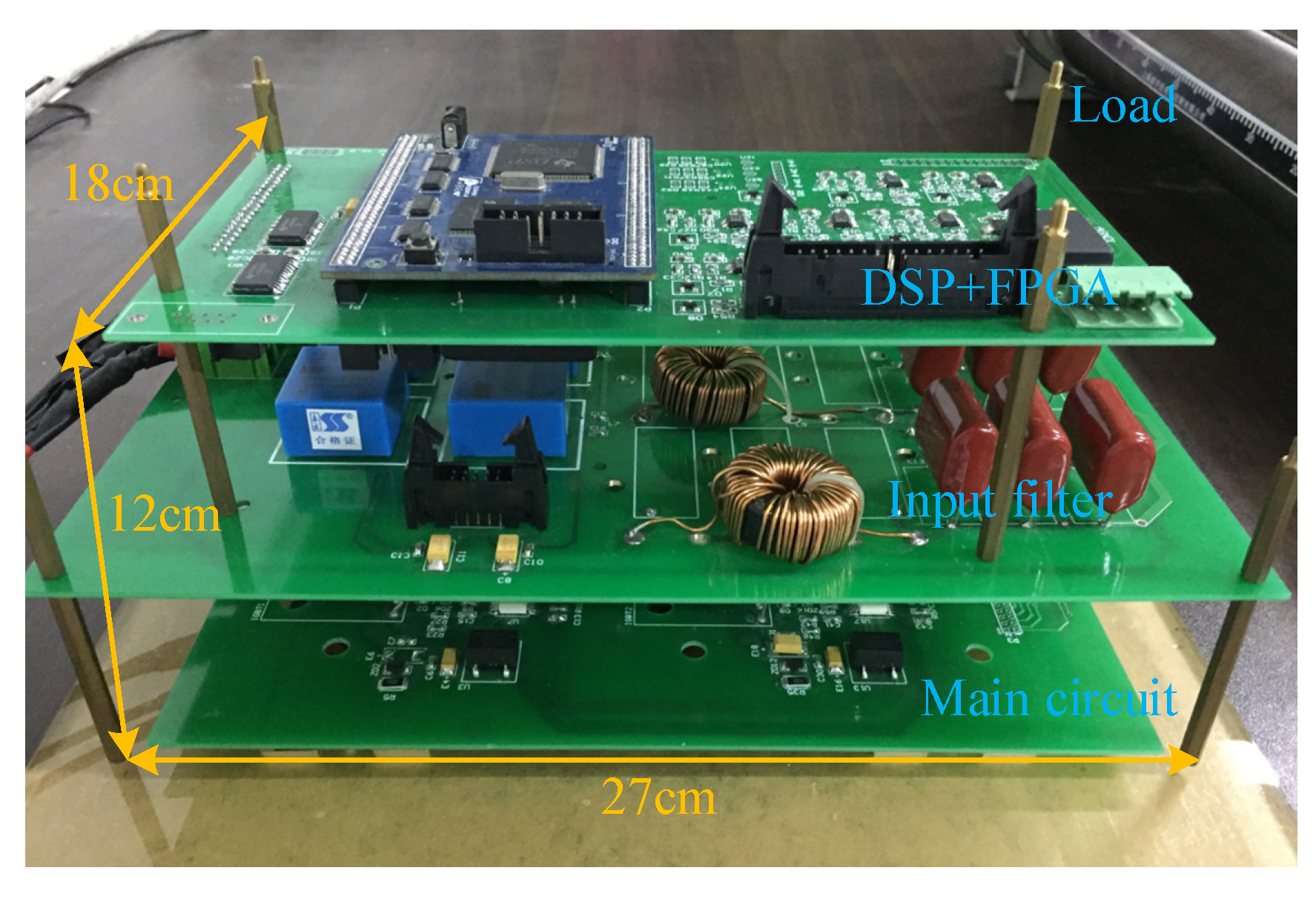
5. Experimental Result
5.1. Voltage Stress
5.2. Unity Power Factor Operation
5.3. Current Stress and Efficiency
5.4. Temperature Rising
6. Conclusions
Author Contributions
Funding
Conflicts of Interest
References
- Kolar, J.W.; Friedli, T. The Essence of three-phase PFC rectifier systems—Part I. IEEE Trans. Power Electron. 2013, 28, 176–198. [Google Scholar] [CrossRef]
- Friedli, T.; Hartmann, M.; Kolar, J.W. The essence of three-phase PFC rectifier systems—Part II. IEEE Trans. Power Electron. 2014, 29, 543–560. [Google Scholar] [CrossRef]
- Lee, J.-Y.; Heo, K.-W.; Kim, K.-T.; Jung, J.-H. Analysis and design of three-phase buck rectifier employing ups to supply high reliable DC power. Energies 2020, 13, 1704. [Google Scholar] [CrossRef]
- Blecharz, K.; Morawiec, M. Nonlinear control of a doubly fed generator supplied by a current source inverter. Energies 2019, 12, 2235. [Google Scholar] [CrossRef]
- Stupar, A.; Friedli, T.; Minibock, J.; Kolar, J.W. Towards a 99% efficient three-phase buck-type PFC rectifier for 400-V DC distribution systems. IEEE Trans. Power Electron. 2012, 27, 1732–1744. [Google Scholar] [CrossRef]
- Xu, F.; Guo, B.; Tolbert, L.M.; Leon, M.T.; Fei, W.; Benjamin, B.J. An all-SiC three-phase buck rectifier for high-efficiency data center power supplies. IEEE Trans. Ind. Appl. 2013, 49, 2662–2673. [Google Scholar] [CrossRef]
- Xu, F.; Guo, B.; Xu, Z.; Tolbert, L.M.; Fei, W.; Benjamin, B.J. Paralleled Three-Phase Current-Source Rectifiers for High-Efficiency Power Supply Applications. IEEE Trans. Ind. Appl. 2015, 51, 2388–2397. [Google Scholar] [CrossRef]
- Yaramasu, V.; Wu, B.; Sen, P.C.; Kouro, S.; Narimani, M. High-power wind energy conversion systems: State-of-the-art and emerging technologies. Proc. IEEE 2015, 103, 740–788. [Google Scholar] [CrossRef]
- Kazmierkowski, M.P.; Malesani, L. Current control techniques for three-phase voltage-source PWM converters: A survey. IEEE Trans. Ind. Electron. 1998, 45, 691–703. [Google Scholar] [CrossRef]
- Suh, Y.; Steinke, J.K.; Steimer, P.K. Efficiency comparison of voltage-source and current-source drive systems for medium-voltage applications. IEEE Trans. Ind. Electron. 2007, 54, 2521–2531. [Google Scholar] [CrossRef]
- Li, Y.; Ding, L.; Li, Y.W. Isomorphic relationships between voltage-source and current-source converters. IEEE Trans. Power Electron. 2020, 34, 7131–7135. [Google Scholar] [CrossRef]
- Rodriguez, J.R.; Dixon, J.W.; Espinoza, J.R.; Pontt, J.; Lezana, P. PWM regenerative rectifiers: State of the art. IEEE Trans. Ind. Electron. 2005, 52, 5–22. [Google Scholar] [CrossRef]
- Wu, B.; Narimani, M. High-Power Converters and AC Drives; John Wiley & Sons: New York, NY, USA, 2006. [Google Scholar]
- Salo, M.; Tuusa, H. A vector controlled current-source PWM rectifier with a novel current damping method. IEEE Trans. Power Electron. 2000, 15, 464–470. [Google Scholar] [CrossRef]
- Slazar, L.S.; Zapata, F.H.; Wiechmann, E.F. Analysis, design and experimental evaluation of a four-pole PWM rectifier using space vector modulation. In Proceedings of the 28th Annual IEEE Power Electronics Specialists Conference, Saint Louis, MO, USA, 27 June 1997; Volume 1, pp. 484–490. [Google Scholar]
- Singh, A.K.; Jeyasankar, E.; Das, P.; Panda, S.K. A matrix-based nonisolated three-phase AC–DC rectifier with large step-down voltage gain. IEEE Trans. Power Electron. 2017, 32, 4796–4811. [Google Scholar] [CrossRef]
- Dang, H.-L.; Jun, E.-S.; Kwak, S. Reduction of DC current ripples by virtual space vector modulation for three-phase AC–DC matrix converters. Energies 2019, 12, 4319. [Google Scholar] [CrossRef]
- Nussbaumer, T.; Baumann, M.; Kolar, J.W. Comprehensive design of a three-phase three-switch buck-type PWM rectifier. IEEE Trans. Power Electron. 2007, 22, 551–562. [Google Scholar] [CrossRef]
- Soeiro, T.B.; Friedli, T.; Kolar, J.W. Design and implementation of a three-phase buck-type third harmonic current injection PFC rectifier SR. IEEE Trans. Power Electron. 2013, 28, 1608–1621. [Google Scholar] [CrossRef]
- Guo, B.; Wang, F.F.; Aeloiza, E. A novel three-phase current source rectifier with delta-type input connection to reduce the device conduction loss. IEEE Trans. Power Electron. 2016, 31, 1074–1084. [Google Scholar] [CrossRef]
- Lei, J.; Feng, S.; Zhao, J.; Chen, W.; Wheeler, P.; Shi, M. An improved three-phase buck rectifier topology with reduced voltage stress on transistors. IEEE Trans. Power Electron. 2020, 35, 2458–2466. [Google Scholar] [CrossRef]
- Silva, M.; Hensgens, N.; Oliver, J.A.; Alou, P.; García, Ó.; Cobos, J.A. Isolated swiss-forward three-phase rectifier with resonant reset. IEEE Trans. Power Electron. 2016, 31, 4795–4808. [Google Scholar] [CrossRef]
- Zhang, B.; Xie, S.; Wang, X.; Xu, J. Modulation method and control strategy for full-bridge-based swiss rectifier to achieve ZVS operation and suppress low-order harmonics of injected current. IEEE Trans. Power Electron. 2020, 35, 6512–6522. [Google Scholar] [CrossRef]
- Afsharian, J.; Xu, D.; Wu, B.; Gong, B.; Yang, Z. The optimal PWM modulation and commutation scheme for a three-phase isolated buck matrix-type rectifier. IEEE Trans. Power Electron. 2018, 33, 110–124. [Google Scholar] [CrossRef]
- Schrittwieser, L.; Leibl, M.; Kolar, J.W. 99% efficient isolated three-phase matrix-type DAB buck–boost PFC rectifier. IEEE Trans. Power Electron. 2019, 35, 138–157. [Google Scholar] [CrossRef]
- Hu, W.; Xie, Y.; Guan, Y.; Wang, Z.; Zhang, Z.; Xu, J. A novel volt-second self-balancing SVPWM scheme to eliminate steady-state DC bias for a three-phase isolated AC-DC matrix converter. IEEE Trans. Power Electron. 2020. [Google Scholar] [CrossRef]
- Korkh, O.; Blinov, A.; Vinnikov, D.; Chub, A. Review of isolated matrix inverters: Topologies, modulation methods and applications. Energies 2020, 13, 2394. [Google Scholar] [CrossRef]
- Jahdi, S.; Alatise, O.; Bonyadi, R.; Alexakis, P.; Fisher, C.A.; Gonzalez, J.O.; Ran, L.; Mawby, P. An analysis of the switching performance and robustness of power MOSFETs body diodes: A technology evaluation. IEEE Trans. Power Electron. 2015, 30, 2383–2394. [Google Scholar] [CrossRef]
- Lin, Z.; Hu, S.; Yuan, Q.; Zhou, X.; Tang, F. Low-reverse recovery charge superjunction MOSFET with a p-type schottky body diode. IEEE Electron. Device Lett. 2017, 38, 1059–1062. [Google Scholar] [CrossRef]
- Grbovic, P.J.; Gruson, F.; Idir, N.; Moigne, P.L. Turn-on performance of reverse blocking IGBT (RB IGBT) and optimization using advanced gate driver. IEEE Trans. Power Electron. 2009, 25, 970–980. [Google Scholar] [CrossRef]
- Sarnago, H.; Lucia, O.; Mediano, A.; Burdio, J.M. Modulation scheme for improved operation of an RB-IGBT-based resonant inverter applied to domestic induction heating. IEEE Trans. Ind. Electron. 2012, 60, 2066–2073. [Google Scholar] [CrossRef]
- Zhou, K.; Huang, L.; Luo, X.; Li, Z.; Li, J.; Dai, G.; Zhang, B. Characterization and performance evaluation of the superjunction RB-IGBT in matrix converter. IEEE Trans. Power Electron. 2017, 33, 3289–3301. [Google Scholar] [CrossRef]
- Guo, B.; Wang, F.; Burgos, R.; Aeloiza, E. Modulation scheme analysis for high-efficiency three-phase buck-type rectifier considering different device combinations. IEEE Trans. Power Electron. 2014, 30, 4750–4761. [Google Scholar] [CrossRef]






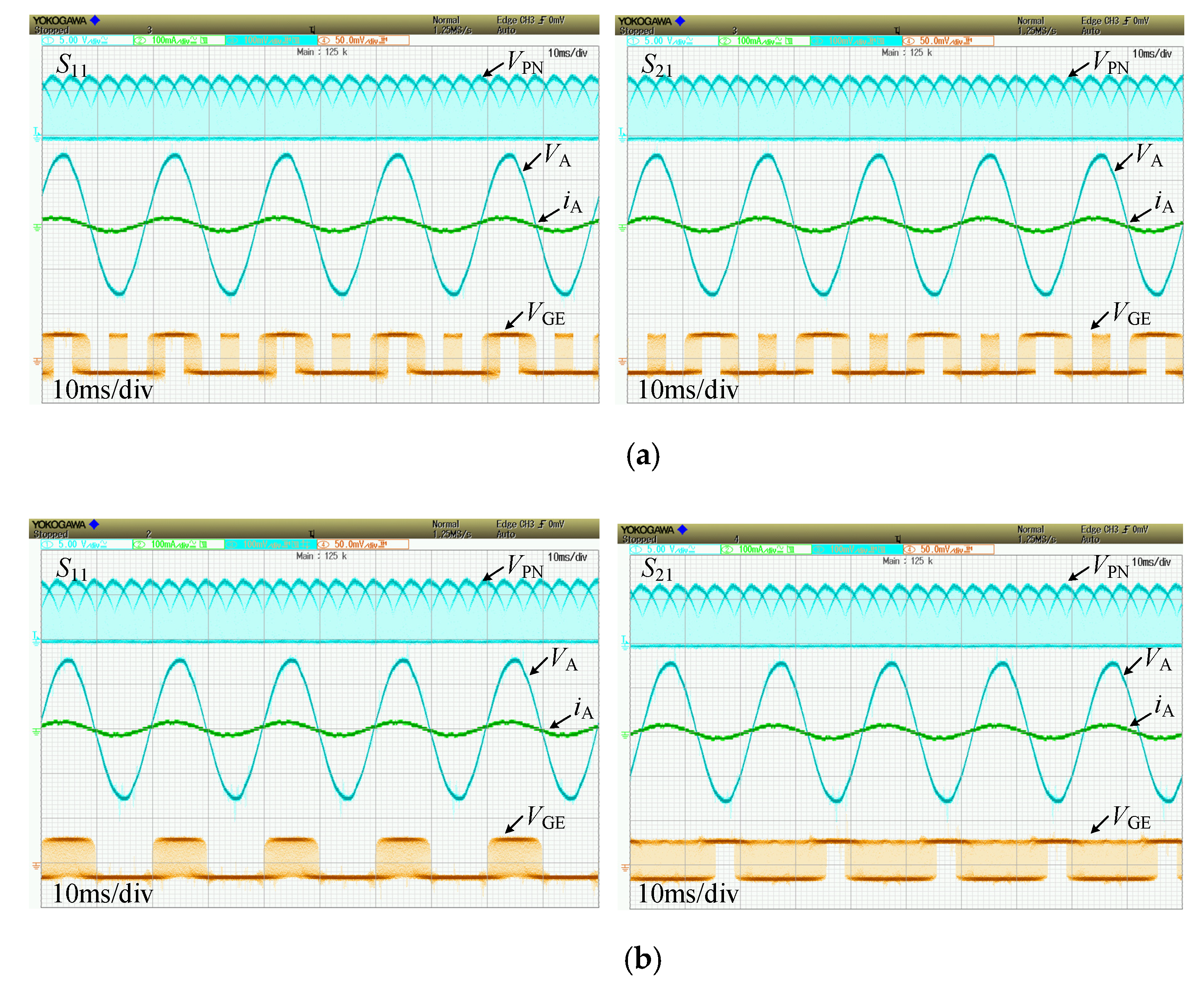


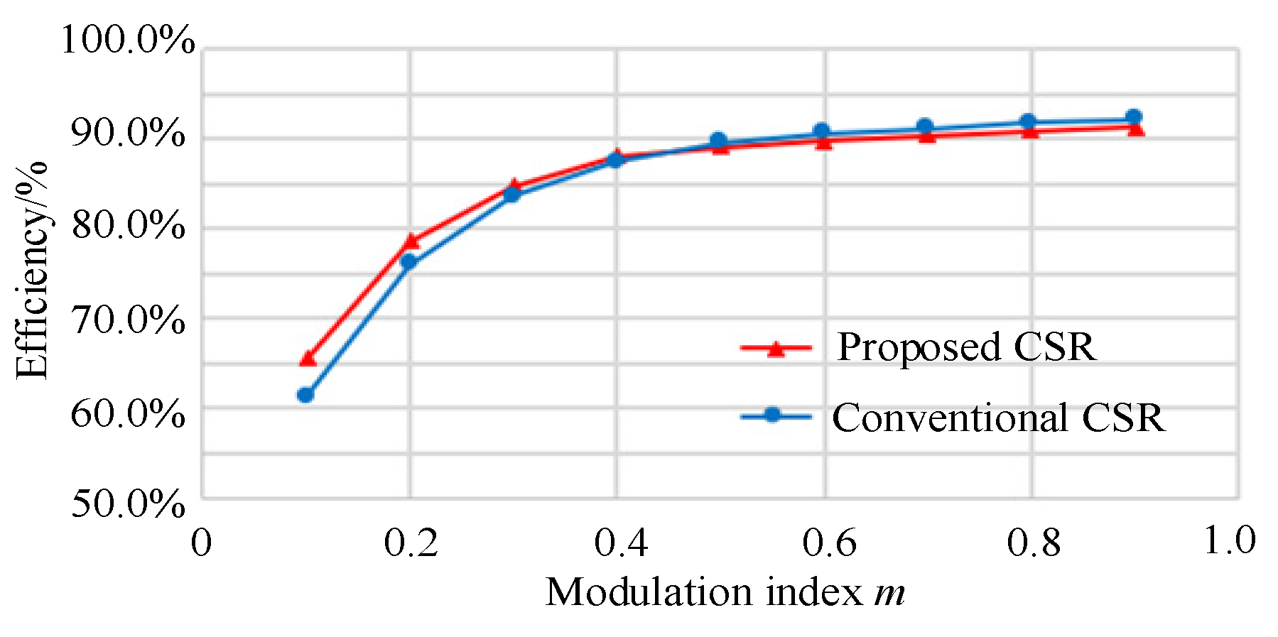

| Vectors | Upper Arm | Lower Arm | VPN | iA | iB | iC | |||||
|---|---|---|---|---|---|---|---|---|---|---|---|
| S11 | S12 | S13 | S21 | S22 | S23 | ||||||
| Active vectors | I1 | √ | × | × | × | × | √ | VAC | io | 0 | −io |
| I2 | × | √ | × | × | × | √ | VBC | 0 | io | −io | |
| I3 | × | √ | × | √ | × | × | VBA | −io | io | 0 | |
| I4 | × | × | √ | √ | × | × | VCA | −io | 0 | io | |
| I5 | × | × | √ | × | √ | × | VCB | 0 | −io | io | |
| I6 | √ | × | × | × | √ | × | VAB | io | −io | 0 | |
| Zero vector | I0 | × | × | × | √ | √ | √ | 0 | 0 | 0 | 0 |
| Conventional CSR | Proposed CSR | ||||||
|---|---|---|---|---|---|---|---|
| Mode 1 | Mode 2 | Mode 3 | Mode 1 | Mode 2 | Mode 3 | ||
| Upper arm | S11 | 0 | 0 | 0 | 0 | 0 | VA−VC |
| S12 | 0 | 0 | 0 | 0 | 0 | VB−VC | |
| S13 | 0 | 0 | 0 | 0 | 0 | 0 | |
| Lower arm | S21 | 0 | 0 | 0 | 0 | 0 | 0 |
| S22 | 0 | 0 | VA−VB | 0 | 0 | 0 | |
| S23 | VB−VC | 0 | VA−VC | VB−VC | 0 | 0 | |
| Conventional CSR | Proposed CSR | ||||||
|---|---|---|---|---|---|---|---|
| Mode 1 | Mode 2 | Mode 3 | Mode 1 | Mode 2 | Mode 3 | ||
| Upper arm | S11 | 0 | VA−VB | VA−VC | 0 | VA−VB | VA−VC |
| S12 | 0 | 0 | VB−VC | 0 | 0 | VB−VC | |
| S13 | 0 | 0 | 0 | 0 | 0 | 0 | |
| Lower arm | S21 | 0 | 0 | 0 | 0 | 0 | 0 |
| S22 | 0 | 0 | 0 | 0 | 0 | 0 | |
| S23 | 0 | 0 | 0 | 0 | 0 | 0 | |
| Number of Devices | Stress on Transistors | Gain | PFC | |||
|---|---|---|---|---|---|---|
| Transistor | Diode | Current | Voltage | |||
| Proposed | 6 | 6 | Low | Low | 1.5 Vim | Yes |
| Six-switch [14] | 6 | 6 | High | High | 1.5 Vim | Yes |
| Four-wire [15] | 8 | 8 | High | High | 1.5 Vim | Yes |
| Current doubler [16] | 12 | 2 | Low | High | 0.75 Vim | Yes |
| Matrix-type [17] | 12 | 0 | High | High | 1.5 Vim | Yes |
| Three-switch [18] | 3 | 12 | High | High | 1.5 Vim | Yes |
| Swiss-type [19] | 8 | 8 | High | High | 1.5 Vim | Yes |
| Delta-type [20] | 6 | 12 | Low | High | 1.5 Vim | Yes |
| Split diode [21] | 6 | 8 | High | Medium | 1.5 Vim | NO |
| Parameter | Symbol | Value/Types |
|---|---|---|
| Input voltage | Vrms | 55 V |
| Input frequency | fg | 50 Hz |
| Input filter resistor | Ri | 5 Ω |
| Input filter inductor | Li | 380 µH |
| Input filter capacitor | Ci | 10 µF |
| Output filter inductor | Lo | 2.5 mH |
| Output filter capacitor | Co | 33 µF |
| Switching frequency | fs | 10 kHz |
| Modulation index | m | 0.8 |
| Output power | Po | 200 W |
| Transistors | S11–S23 | FGA25N120 |
| Diodes | D11–D23 | RHRG30120 |
| Control circuit | DSP + FPGA | TMS320F28335/ CoreEP4CE6d |
© 2020 by the authors. Licensee MDPI, Basel, Switzerland. This article is an open access article distributed under the terms and conditions of the Creative Commons Attribution (CC BY) license (http://creativecommons.org/licenses/by/4.0/).
Share and Cite
Hu, W.; Xie, Y.; Wang, Z.; Zhang, Z. A Novel Three-Phase Current Source Rectifier Based on an Asymmetrical Structure to Reduce Stress on Semiconductor Devices. Energies 2020, 13, 3331. https://doi.org/10.3390/en13133331
Hu W, Xie Y, Wang Z, Zhang Z. A Novel Three-Phase Current Source Rectifier Based on an Asymmetrical Structure to Reduce Stress on Semiconductor Devices. Energies. 2020; 13(13):3331. https://doi.org/10.3390/en13133331
Chicago/Turabian StyleHu, Wang, Yunxiang Xie, Zhiping Wang, and Zhi Zhang. 2020. "A Novel Three-Phase Current Source Rectifier Based on an Asymmetrical Structure to Reduce Stress on Semiconductor Devices" Energies 13, no. 13: 3331. https://doi.org/10.3390/en13133331
APA StyleHu, W., Xie, Y., Wang, Z., & Zhang, Z. (2020). A Novel Three-Phase Current Source Rectifier Based on an Asymmetrical Structure to Reduce Stress on Semiconductor Devices. Energies, 13(13), 3331. https://doi.org/10.3390/en13133331


