Estimation of Bearing Fault Severity in Line-Connected and Inverter-Fed Three-Phase Induction Motors

 ,
,  ,
,
Abstract
:1. Introduction
2. Methodology
- Strategy 1: This strategy classifies up to four predefined patterns representing qualitative ranges of severity, where level 1 represents first bearing wear, level 2 considers moderate wear, and level 3 represents an advanced failure. Finally, level 4 considers a bearing operating at critical conditions.
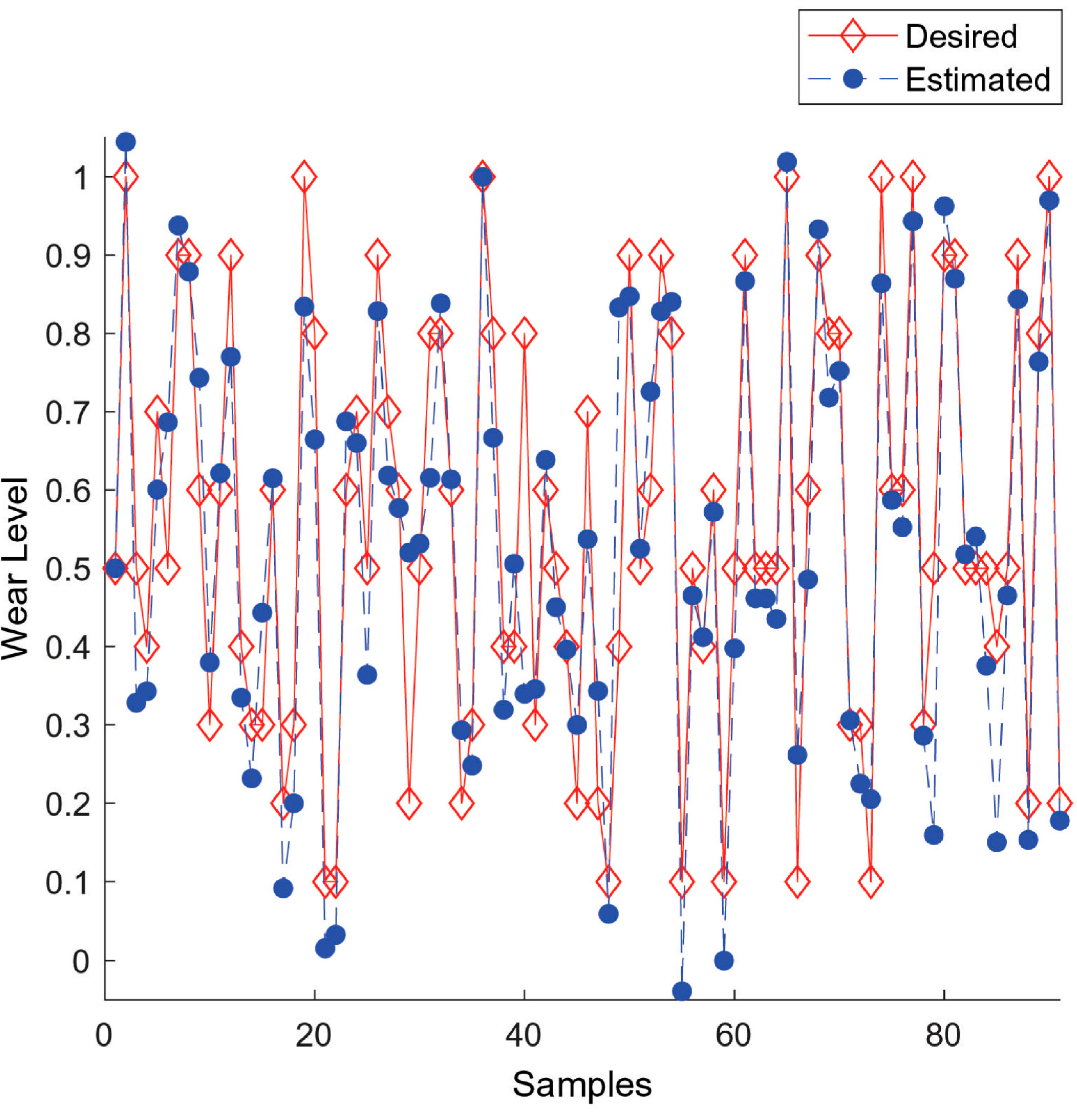
- Strategy 2: An estimator performs a functional approximation, identifying up to ten levels of severity, in which levels 1 and 10 represent the most initial degradation level of a fault evolving to the most critical situation, respectively.
3. Case Study
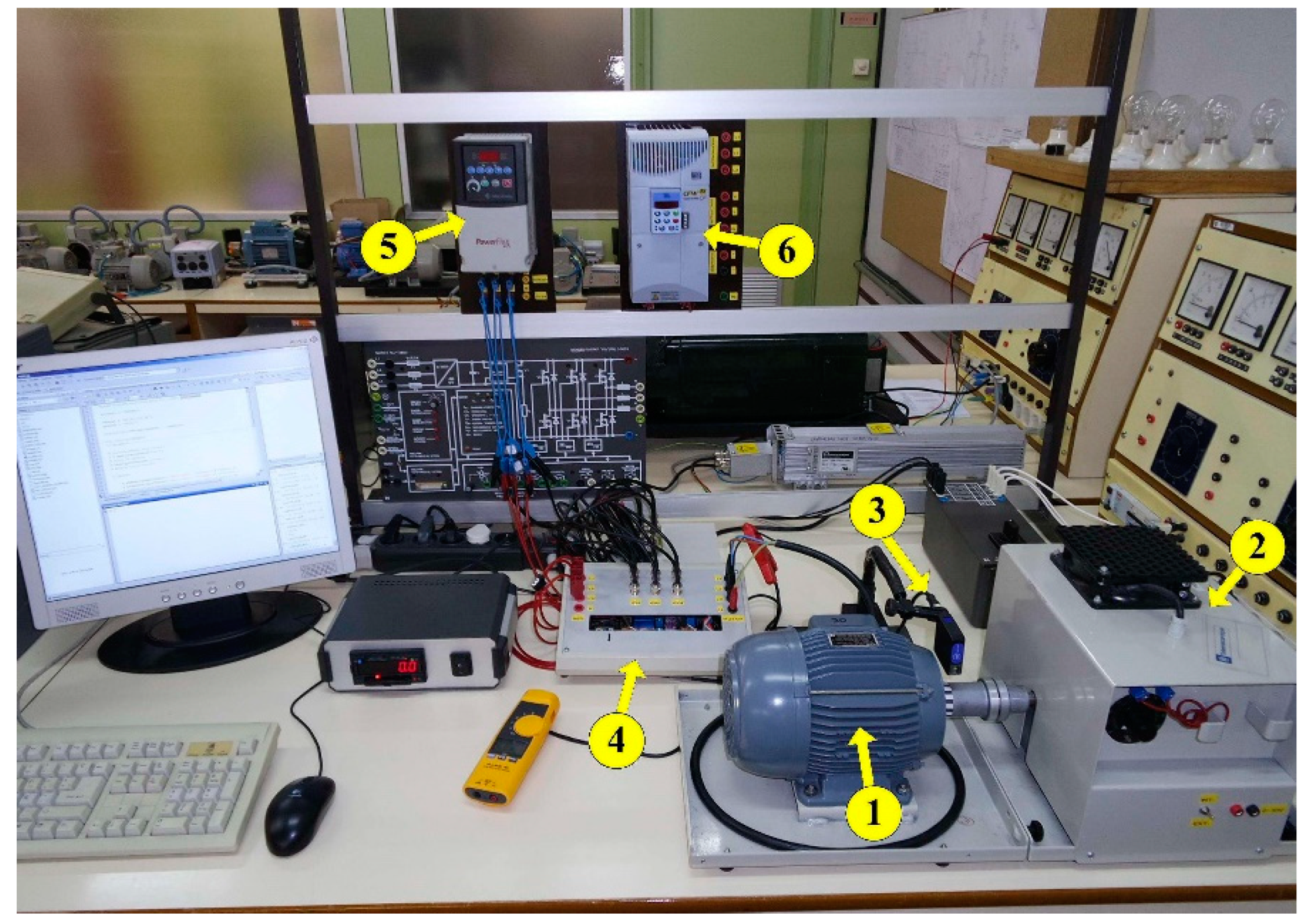
3.1. Test Bench
3.2. Experimental Results
3.3. Strategy 1—Determination of Bearing Fault Level
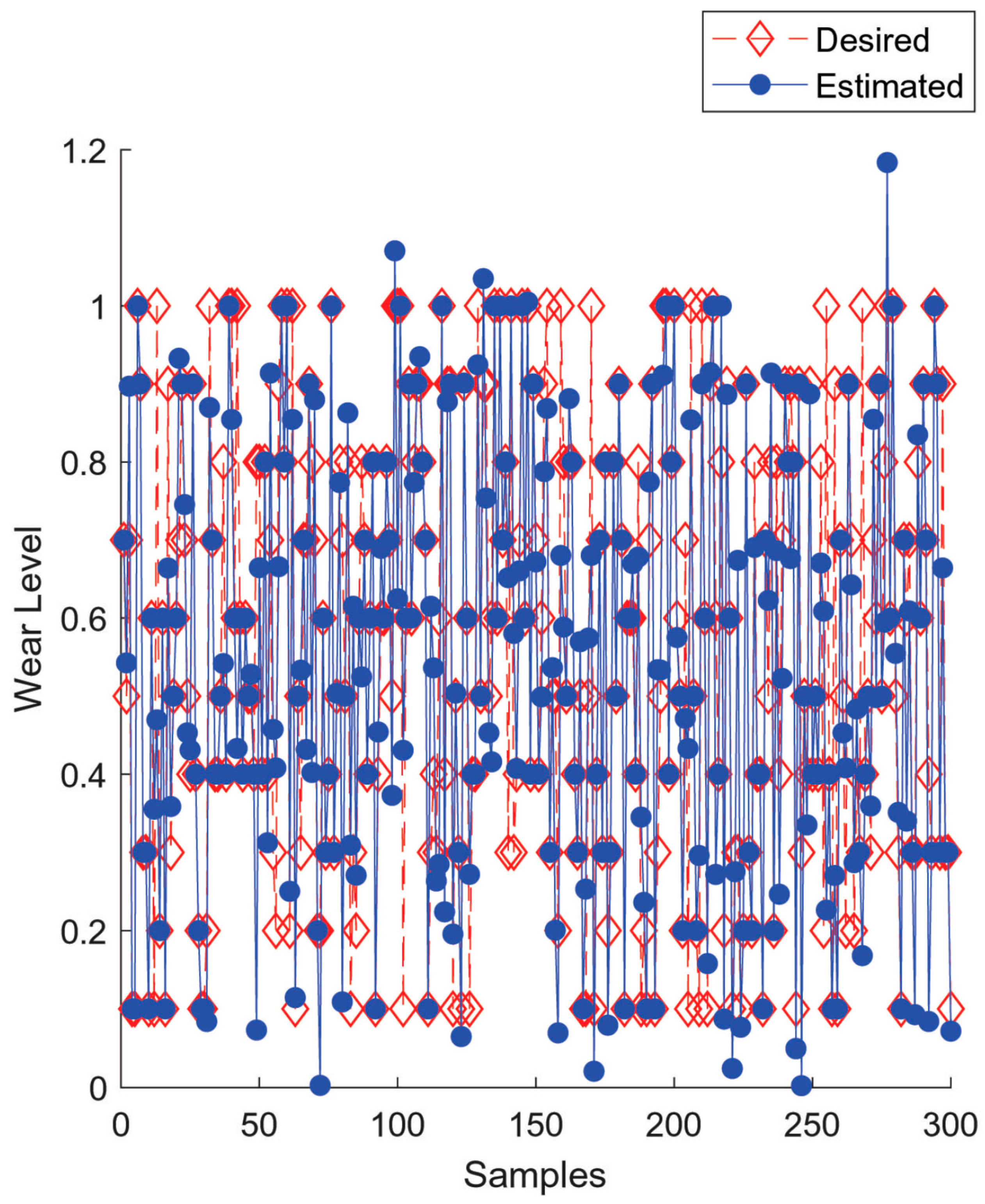
3.4. Strategy 2—Estimation of Bearing Fault Severity
3.5. Comparison with Some Previous Research
4. Conclusions
Author Contributions
Funding
Acknowledgments
Conflicts of Interest
References
- Leite, V.C.M.N.; da Silva, J.G.B.; Veloso, G.F.C.; da Silva, L.E.B.; Lambert-Torres, G.; Bonaldi, E.L.; de Oliveira, L.E.L. Detection of localized bearing faults in induction machines by spectral kurtosis and envelope analysis of stator current. IEEE Trans. Ind. Electron. 2015, 62, 1855–1865. [Google Scholar] [CrossRef]
- Wang, Z.; Yang, J.; Li, H.; Zhen, D.; Xu, Y.; Gu, F. Fault identification of broken rotor bars in induction motors using an improved cyclic modulation spectral analysis. Energies 2019, 12, 3279. [Google Scholar] [CrossRef] [Green Version]
- Dalvand, F.; Kalantar, A.; Safizadeh, M.S. A novel bearing condition monitoring method in induction motors based on instantaneous frequency of motor voltage. IEEE Trans. Ind. Electron. 2016, 63, 364–376. [Google Scholar] [CrossRef]
- Kang, M.; Kim, J.; Kim, J.M. High-performance and energy-efficient fault diagnosis using effective envelope analysis and denoising on a general-purpose graphics processing unit. IEEE Trans. Power Electron. 2015, 30, 2763–2776. [Google Scholar] [CrossRef]
- Riera-Guasp, M.; Antonino-Daviu, J.A.; Capolino, G.A. Advances in electrical machine, power electronic, and drive condition monitoring and fault detection: State of the art. IEEE Trans. Ind. Electron. 2015, 62, 1746–1759. [Google Scholar] [CrossRef]
- Bellini, A.; Filippetti, F.; Tassoni, C.; Capolino, G.A. Advances in diagnostic techniques for induction machines. IEEE Trans. Ind. Electron. 2008, 55, 4109–4126. [Google Scholar] [CrossRef]
- Toma, R.N.; Prosvirin, A.E.; Kim, J.M. Bearing fault diagnosis of induction motors using a genetic algorithm and machine learning classifiers. Sensors 2020, 20, 1884. [Google Scholar] [CrossRef] [PubMed] [Green Version]
- Muetze, A.; Binder, A. Practical rules for assessment of inverter-induced bearing currents in inverter-fed ac motors up to 500 kW. IEEE Trans. Ind. Electron. 2007, 54, 1614–1622. [Google Scholar] [CrossRef]
- Mishra, C.; Samantaray, A.; Chakraborty, G. Rolling element bearing defect diagnosis under variable speed operation through angle synchronous averaging of wavelet de-noised estimate. Mech. Syst. Signal Process. 2016, 72–73, 206–222. [Google Scholar] [CrossRef]
- Prudhom, A.; Antonino-Daviu, J.A.; Razik, H.; Climente-Alarcon, V. Time-frequency vibration analysis for the detection of motor damages caused by bearing currents. Mech. Syst. Signal Process. 2017, 84, 747–762. [Google Scholar] [CrossRef] [Green Version]
- Ren, X.; Liu, R.; Yang, E. Modelling of the bearing breakdown resistance in bearing currents problem of AC motors. Energies 2019, 12, 1121. [Google Scholar] [CrossRef] [Green Version]
- Sadegh, H.; Mehdi, A.N.; Mehdi, A. Classification of acoustic emission signals generated from journal bearing at different lubrication conditions based on wavelet analysis in combination with artificial neural network and genetic algorithm. Tribol. Int. 2016, 95, 426–434. [Google Scholar] [CrossRef]
- Saidi, L.; Ali, J.B.; Fnaiech, F. Bi-spectrum based-EMD applied to the non-stationary vibration signals for bearing faults diagnosis. ISA Trans. 2014, 53, 1650–1660. [Google Scholar] [CrossRef] [PubMed]
- Al-Bugharbee, H.; Trendafilova, I. A fault diagnosis methodology for rolling element bearings based on advanced signal pretreatment and autoregressive modelling. J. Sound Vib. 2016, 369, 246–265. [Google Scholar] [CrossRef] [Green Version]
- Zhu, D.; Gao, Q.; Sun, D.; Lu, Y.; Peng, S. A detection method for bearing faults using null space pursuit and S transform. Signal Process. 2014, 96, 80–89. [Google Scholar] [CrossRef]
- Maruthi, G.S.; Hegde, V. Application of MEMS Accelerometer for Detection and Diagnosis of Multiple Faults in the Roller Element Bearings of Three Phase Induction Motor. IEEE Sens. J. 2016, 16, 145–152. [Google Scholar] [CrossRef]
- Smith, W.A.; Fan, Z.; Peng, Z.; Li, H.; Randall, R.B. Optimised Spectral Kurtosis for bearing diagnostics under electromagnetic interference. Mech. Syst. Signal Process. 2016, 75, 371–394. [Google Scholar] [CrossRef] [Green Version]
- Wang, T.; Liang, M.; Li, J.; Cheng, W.; Li, C. Bearing fault diagnosis under unknown variable speed via gear noise cancellation and rotational order sideband identification. Mech. Syst. Signal Process. 2015, 62, 30–53. [Google Scholar] [CrossRef]
- Immovilli, F.; Bellini, A.; Rubini, R.; Tassoni, C. Diagnosis of bearing faults in induction machines by vibration or current signals: A critical comparison. IEEE Trans. Ind. Appl. 2010, 46, 1350–1359. [Google Scholar] [CrossRef]
- Blodt, M.; Granjon, P.; Raison, B.; Rostaing, G. Models for bearing damage detection in induction motors using stator current monitoring. IEEE Trans. Ind. Electron. 2008, 55, 1813–1822. [Google Scholar] [CrossRef] [Green Version]
- Picazo-Ródenas, M.J.; Antonino-Daviu, J.; Climente-Alarcon, V.; Royo-Pastor, R.; Mota-Villar, A. Combination of noninvasive approaches for general assessment of induction motors. IEEE Trans. Ind. Appl. 2015, 51, 2172–2180. [Google Scholar] [CrossRef] [Green Version]
- Chang, H.-C.; Jheng, Y.-M.; Kuo, C.-C.; Hsueh, Y.-M. Induction motors condition monitoring system with fault diagnosis using a hybrid approach. Energies 2019, 12, 1471. [Google Scholar] [CrossRef] [Green Version]
- Yang, T.; Pen, H.; Wang, Z.; Chang, C.S. Feature knowledge based fault detection of induction motors through the analysis of stator current data. IEEE Trans. Instrum. Meas. 2016, 65, 549–558. [Google Scholar] [CrossRef]
- Rai, A.; Upadhyay, S. A review on signal processing techniques utilized in the fault diagnosis of rolling element bearings. Tribol. Int. 2016, 96, 289–306. [Google Scholar] [CrossRef]
- Skora, M.M.; Ewert, P.; Kowalski, C.T. Selected rolling bearing fault diagnostic methods in wheel embedded permanent magnet brushless direct current motors. Energies 2019, 12, 4212. [Google Scholar] [CrossRef] [Green Version]
- Esakimuthu Pandarakone, S.; Mizuno, Y.; Nakamura, H. A Comparative study between machine learning algorithm and artificial intelligence neural network in detecting minor bearing fault of induction motors. Energies 2019, 12, 2105. [Google Scholar] [CrossRef] [Green Version]
- Jia, F.; Lei, Y.; Lin, J.; Zhou, X.; Lu, N. Deep neural networks: A promising tool for fault characteristic mining and intelligent diagnosis of rotating machinery with massive data. Mech. Syst. Signal Process. 2016, 72, 303–315. [Google Scholar] [CrossRef]
- Xu, Z.; Li, Y.; Wang, Z.; Xuan, J. A selective fuzzy {ARTMAP} ensemble and its application to the fault diagnosis of rolling element bearing. Neurocomputing 2016, 182, 25–35. [Google Scholar] [CrossRef]
- Tran, V.T.; AlThobiani, F.; Ball, A.; Choi, B.K. An application to transient current signal based induction motor fault diagnosis of Fourier Bessel expansion and simplified fuzzy ARTMAP. Expert Syst. Appl. 2013, 40, 5372–5384. [Google Scholar] [CrossRef] [Green Version]
- Li, C.; de Oliveira, J.V.; Cerrada, M.; Pacheco, F.; Cabrera, D.; Sanchez, V.; Zurita, G. Observer-biased bearing condition monitoring: Fromfault detection to multi-fault classification. Eng. Appl. Artif. Intell. 2016, 50, 287–301. [Google Scholar] [CrossRef] [Green Version]
- Ali, J.B.; Saidi, L.; Mouelhi, A.; Chebel-Morello, B.; Fnaiech, F. Linear feature selection and classification using PNN and SFAM neural networks for a nearly online diagnosis of bearing naturally progressing degradations. Eng. Appl. Artif. Intell. 2015, 42, 67–81. [Google Scholar]
- Saidi, L.; Ali, J.B.; Fnaiech, F. Application of higher order spectral features and support vector machines for bearing faults classification. ISA Trans. 2015, 54, 193–206. [Google Scholar] [CrossRef] [PubMed]
- Huang, T.; Fu, S.; Feng, H.; Kuang, J. Bearing fault diagnosis based on shallow multi-scale convolutional neural network with attention. Energies 2019, 12, 3937. [Google Scholar] [CrossRef] [Green Version]
- Wan, L.; Li, H.; Chen, Y.; Li, C. Rolling bearing fault prediction method based on QPSO-BP neural network and dempster–shafer evidence theory. Energies 2020, 13, 1094. [Google Scholar] [CrossRef]
- Do Nascimento, C.F.; de Oliveira, A.A., Jr.; Goedtel, A.; Serni, P.J.A. Harmonic identification using parallel neural networks in single-phase systems. Appl. Soft Comput. 2011, 11, 2178–2185. [Google Scholar] [CrossRef]
- Godoy, W.F.; da Silva, I.N.; Goedtel, A.; Palácios, R.H.C.; Lopes, T.D. Application of intelligent tools to detect and classify broken rotor bars in three-phase induction motors fed by an inverter. IET Electr. Power Appl. 2016, 10, 430–439. [Google Scholar] [CrossRef]
- Haykin, S.O. Neural Networks and Learning Machines, Hardcover, 3rd ed.; Prentice Hall: Upper Saddle River, NJ, USA, 2008. [Google Scholar]
- Lopes, T.D.; Goedtel, A.; Palácios, R.H.C.; Godoy, W.F.; de Souza, R.M. Bearing fault identification of three-phase induction motors bases on two current sensor strategy. Soft Comput. 2017, 21, 6673–6685. [Google Scholar] [CrossRef]
- Drif, M.; Cardoso, A. Stator fault diagnostics in squirrel cage three-phase induction motor drives using the instantaneous active and reactive power signature analyses. IEEE Trans. Ind. Inform. 2014, 10, 1348–1360. [Google Scholar] [CrossRef]
- Barendse, P.; Pillay, P. The detection of unbalanced faults in inverter-fed induction machines. In Proceedings of the IEEE International Symposium on Diagnostics for Electric Machines, Power Electronics and Drives, Cracow, Poland, 6 September 2007; pp. 46–51. [Google Scholar]
- Wolbank, T.; Nussbaumer, P.; Chen, H.; Macheiner, P. Monitoring of rotor-bar defects in inverter-fed induction machines at zero load and speed. IEEE Trans. Ind. Electron. 2011, 58, 1468–1478. [Google Scholar] [CrossRef]
- Chua, T.; Tan, W.W.; Wang, Z.X.; Chang, C. Hybrid time-frequency domain analysis for inverter-fed induction motor fault detection. In Proceedings of the IEEE International Symposium on Industrial Electronics (ISIE), Bari, Italy, 4 July 2010; pp. 1633–1638. [Google Scholar]
- Basaran, M.; Ece, D. Detection of mechanical faults in induction motors supplied with adjustable speed drives. In Proceedings of the IEEE International Electric Machines and Drives Conference (IEMDC), Miami, FL, USA, 3 May 2009; pp. 1414–1419. [Google Scholar]
- Araújo, R.; Rodrigues, R.A.; De Paula, H.; Baccarini, L.M.R. Premature wear and recurrent bearing failures at an MIT: A case study. In Proceedings of the 9th IEEE/IAS International Conference on Industry Applications (INDUSCON), Sao Paulo, Brazil, 8 November 2010; pp. 1–6. (In Portuguese). [Google Scholar]
- Faiz, J.; Ghorbanian, V.; Ebrahimi, B. Locating broken bars in line-start and inverter-fed induction motors using modified winding function method. Electromagnetics 2012, 32, 173–192. [Google Scholar] [CrossRef]
- Briz, F.; Degner, M.; Guerrero, J.; Garcia, P. Stator windings fault diagnostics of induction machines operated from inverters and soft-starters using high-frequency negative-sequence currents. IEEE Trans. Ind. Appl. 2009, 45, 1637–1646. [Google Scholar] [CrossRef]
- Seshadrinath, J.; Singh, B.; Panigrahi, B. Investigation of vibration signatures for multiple fault diagnosis in variable frequency drives using complex wavelets. IEEE Trans. Power Electron. 2014, 9, 936–945. [Google Scholar] [CrossRef]
- Jin, X.; Yuan, F.; Chow, T.W.; Zhao, M. Weighted local and global regressive mapping: A new manifold learning method for machine fault classification. Eng. Appl. Artif. Intell. 2014, 30, 118–128. [Google Scholar] [CrossRef]
- Liu, Z.; Cao, H.; Chen, X.; He, Z.; Shen, Z. Multi-fault classification based on wavelet SVM with PSO algorithm to analyze vibration signals from rolling element bearings. Neurocomputing 2013, 99, 399–410. [Google Scholar] [CrossRef]


| Parameters | Specifications |
|---|---|
| Hole diameter (mm) | 20 |
| External diameter (mm) | 42 |
| Width (mm) | 12 |
| Dynamic load (kN) | 9.95 |
| Static load (kN) | 5 |
| Reference speed (r/min) | 38,000 |
| Limit speed (r/min) | 24,000 |
| Supply | Frequency | Switching Frequency | Bearing Condition | Nº of Acquisitions | |
|---|---|---|---|---|---|
| 1 | Allen Bradley | 50 Hz | 4 kHz | Healthy Faulty | 40 100 |
| 2 | Allen Bradley | 25 Hz | 4 kHz | Healthy Faulty | 40 100 |
| 3 | Allen Bradley | 75 Hz | 4 kHz | Healthy Faulty | 40 100 |
| 4 | Allen Bradley | 50 Hz | 5 kHz | Healthy Faulty | 40 100 |
| 5 | WEG | 50 Hz | 5 kHz | Healthy Faulty | 40 100 |
| 6 | Line-fed | 50 Hz | Healthy Faulty | 40 100 |
| Attributes | Line Connected | Inverter-Fed Supply | ||
|---|---|---|---|---|
| Correctly classified instances (%) | 98.6 | 81.96 | ||
| Incorrectly classified instances (%) | 1.39 | 18.04 | ||
| Kappa statistic | 0.97 | 0.58 | ||
| Mean absolute error | 0.01 | 0.18 | ||
| Root mean squared error | 0.10 | 0.37 | ||
| Relative absolute error (%) | 4.92 | 44.65 | ||
| Root relative squared error (%) | 23.74 | 80.49 | ||
| Detailed accuracy by class | Healthy | Defective | Healthy | Defective |
| TP rate 1 | 0.97 | 0.99 | 0.70 | 0.87 |
| FP rate 2 | 0.01 | 0.02 | 0.12 | 0.29 |
| Precision | 0.97 | 0.99 | 0.71 | 0.87 |
| Recall | 0.97 | 0.99 | 0.70 | 0.87 |
| F measure | 0.97 | 0.99 | 0.70 | 0.87 |
| MCC 3 | 0.97 | 0.97 | 0.57 | 0.57 |
| ROC 4 | 0.99 | 0.99 | 0.90 | 0.90 |
| Area | 0.99 | 1.00 | 0.82 | 0.95 |
| Predict Classes | ||||
|---|---|---|---|---|
| Line-connected | Inverter-fed | |||
| Classes | Healthy | Defective | Healthy | Defective |
| Healthy | 36 | 1 | 124 | 53 |
| Defective | 1 | 105 | 50 | 344 |
| Attributes | Line Connected | Inverter-Fed Supply | ||||||
|---|---|---|---|---|---|---|---|---|
| Correctly classified instances (%) | 93.13 | 80.22 | ||||||
| Incorrectly classified instances (%) | 6.86 | 19.77 | ||||||
| Kappa statistic | 0.90 | 0.73 | ||||||
| Mean absolute error | 0.06 | 0.10 | ||||||
| Root mean squared error | 0.19 | 0.28 | ||||||
| Relative absolute error (%) | 16.93 | 29.04 | ||||||
| Root relative squared error (%) | 43.06 | 66.09 | ||||||
| Detailed accuracy by class | Level 1 | Level 2 | Level 3 | Level 4 | Level 1 | Level 2 | Level 3 | Level 4 |
| TP rate 1 | 0.83 | 0.96 | 0.96 | 0.96 | 0.72 | 0.82 | 0.83 | 0.83 |
| FP rate 2 | 0.01 | 0.08 | 0.00 | 0.00 | 0.04 | 0.10 | 0.09 | 0.03 |
| Precision | 0.95 | 0.81 | 1.00 | 1.00 | 0.83 | 0.76 | 0.79 | 0.84 |
| Recall | 0.83 | 0.96 | 0.96 | 0.95 | 0.72 | 0.81 | 0.83 | 0.83 |
| F measure | 0.88 | 0.88 | 0.98 | 0.97 | 0.77 | 0.79 | 0.81 | 0.84 |
| MCC 3 | 0.86 | 0.84 | 0.97 | 0.97 | 0.72 | 0.70 | 0.72 | 0.81 |
| ROC 4 | 0.95 | 0.95 | 1.00 | 0.99 | 0.93 | 0.90 | 0.93 | 0.94 |
| Area | 0.87 | 0.91 | 1.00 | 0.99 | 0.85 | 0.85 | 0.86 | 0.87 |
| Predicted Classes | ||||
|---|---|---|---|---|
| Line-connected | ||||
| Classes | Level 1 | Level 2 | Level 3 | Level 4 |
| Level 1 | 20 | 4 | 0 | 0 |
| Level 2 | 1 | 27 | 0 | 0 |
| Level 3 | 0 | 1 | 28 | 0 |
| Level 4 | 0 | 1 | 0 | 20 |
| Inverter-fed | ||||
| Classes | Level 1 | Level 2 | Level 3 | Level 4 |
| Level 1 | 97 | 23 | 14 | 0 |
| Level 2 | 15 | 148 | 14 | 4 |
| Level 3 | 3 | 18 | 157 | 12 |
| Level 4 | 1 | 4 | 13 | 89 |
© 2020 by the authors. Licensee MDPI, Basel, Switzerland. This article is an open access article distributed under the terms and conditions of the Creative Commons Attribution (CC BY) license (http://creativecommons.org/licenses/by/4.0/).
Share and Cite
Fontes Godoy, W.; Morinigo-Sotelo, D.; Duque-Perez, O.; Nunes da Silva, I.; Goedtel, A.; Palácios, R.H.C. Estimation of Bearing Fault Severity in Line-Connected and Inverter-Fed Three-Phase Induction Motors. Energies 2020, 13, 3481. https://doi.org/10.3390/en13133481
Fontes Godoy W, Morinigo-Sotelo D, Duque-Perez O, Nunes da Silva I, Goedtel A, Palácios RHC. Estimation of Bearing Fault Severity in Line-Connected and Inverter-Fed Three-Phase Induction Motors. Energies. 2020; 13(13):3481. https://doi.org/10.3390/en13133481
Chicago/Turabian StyleFontes Godoy, Wagner, Daniel Morinigo-Sotelo, Oscar Duque-Perez, Ivan Nunes da Silva, Alessandro Goedtel, and Rodrigo Henrique Cunha Palácios. 2020. "Estimation of Bearing Fault Severity in Line-Connected and Inverter-Fed Three-Phase Induction Motors" Energies 13, no. 13: 3481. https://doi.org/10.3390/en13133481