Article

Multiphase PMSM with Asymmetric Windings for Electric Drive

School of Electrical Engineering and Automation, Harbin Institute of Technology, Harbin 150080, China
*
Author to whom correspondence should be addressed.
Energies 2020, 13(15), 3765; https://doi.org/10.3390/en13153765
Submission received: 8 June 2020 / Revised: 9 July 2020 / Accepted: 19 July 2020 / Published: 22 July 2020
(This article belongs to the Section E: Electric Vehicles)

Abstract

:
Multiphase permanent magnet synchronous motors (PMSM) are widely utilized in high power and high reliability electric propulsion systems. In electric propulsion systems, the motor may work at a low efficiency area for a long time, which increases energy consumption and reduces cruise range. In order to improve motor efficiency, this paper proposes a multiphase motor structure. The stator winding of proposed motor consists of three independent windings that have different rated speed and torque. In this paper, winding match mode, operation characteristic and efficiency characteristic are analyzed, and a torque distribution strategy with optimal efficiency is given. The results show that in propeller load such as electric aircrafts and ships, the proposed motor can reduce motor total loss and temperature rise in a drive cycle, which improves system efficiency, reliability and fault tolerance performance.

Graphical Abstract

1. Introduction

Electric drive systems have been widely used in electric vehicles, aircrafts and ships because of high efficiency, high reliability and low emission and pollution [1,2,3,4,5,6]. In these fields, the motor works at complex drive cycle and the output speed and torque vary frequently, which reduces system efficiency. Much research focuses on the optimization of motor design and control in order to improve system efficiency, power density and cruise range.
Multiphase motors can improve system power density and reliability and have fault tolerance ability. These advantages make it fit for all electric aircrafts and ships, where high power, reliability and safety are required. In these cases, multiphase motors have preference instead of three-phase motor. Among multiphase motors [7,8,9,10], five-phase, double three-phase, twelve-phase and fifteen-phase are normal choices according to application and power level [11,12,13].
In order to improve efficiency of the electric drive system, research on the optimization of motor structure and control strategy were taken in past decades. Some researchers make efforts to improve motor performance under high temperature by optimizing the structure of motor stator and rotor [14,15,16]. Moreover, a superconducting motor is used to reduce copper loss and improve efficiency in high power cases [17,18,19]. For motor control strategy, maximum efficiency control, optimal sliding mode control and stochastic model are proposed [20,21,22]. These control methods are able to optimize current control and reduce motor losses. The above research and methods are beneficial to improve the actual operation efficiency of the electric drive system. Yet, most of the research focuses on the performance optimization of the motor and control system itself and does not combine motor optimization with actual working conditions.
In electric drive applications, for a long time, the motor works at a low power area, where efficiency is relatively lower. As the battery capacity is limited, the cruise range will reduce.
This paper presents an asymmetric winding multi-phase motor, where stator winding is divided into three independent sets of windings. The three sets of windings have the same rated torque but a different rated speed. This structure can realize optimal efficiency by distributing the current and torque of each set of windings reasonably.
In this paper, relationship between the motor characteristics and its work area will be discussed. The motor model is established to analyze the winding matching method and the performance. This paper also compares the efficiency characteristics of proposed motor with conventional motor to illustrate the advantage and existing problems of the proposed structure for further research.

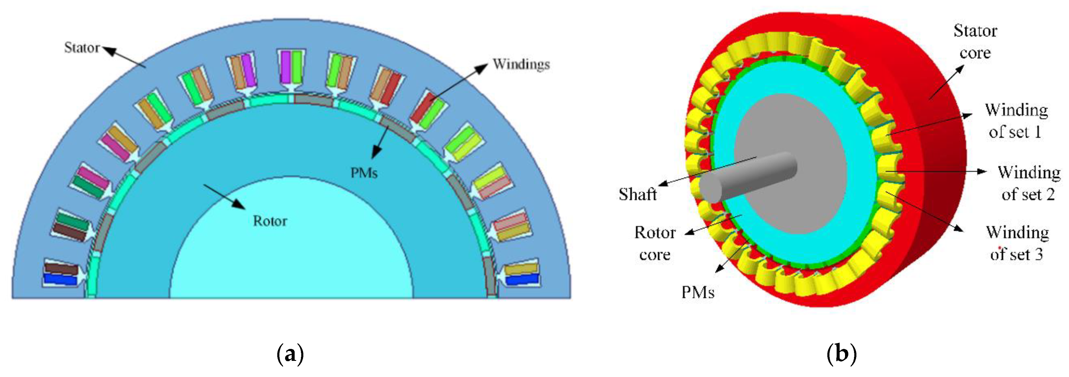
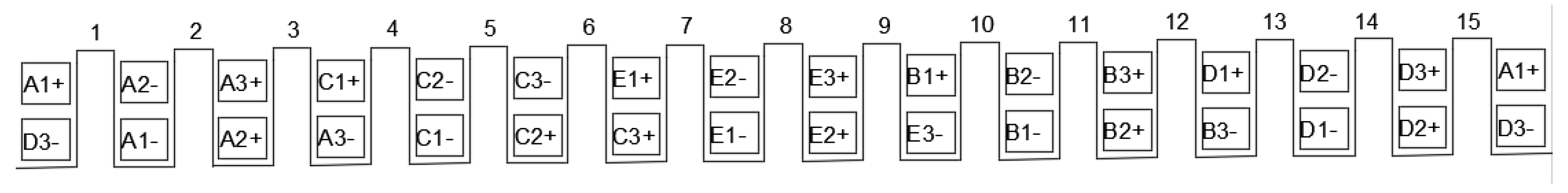
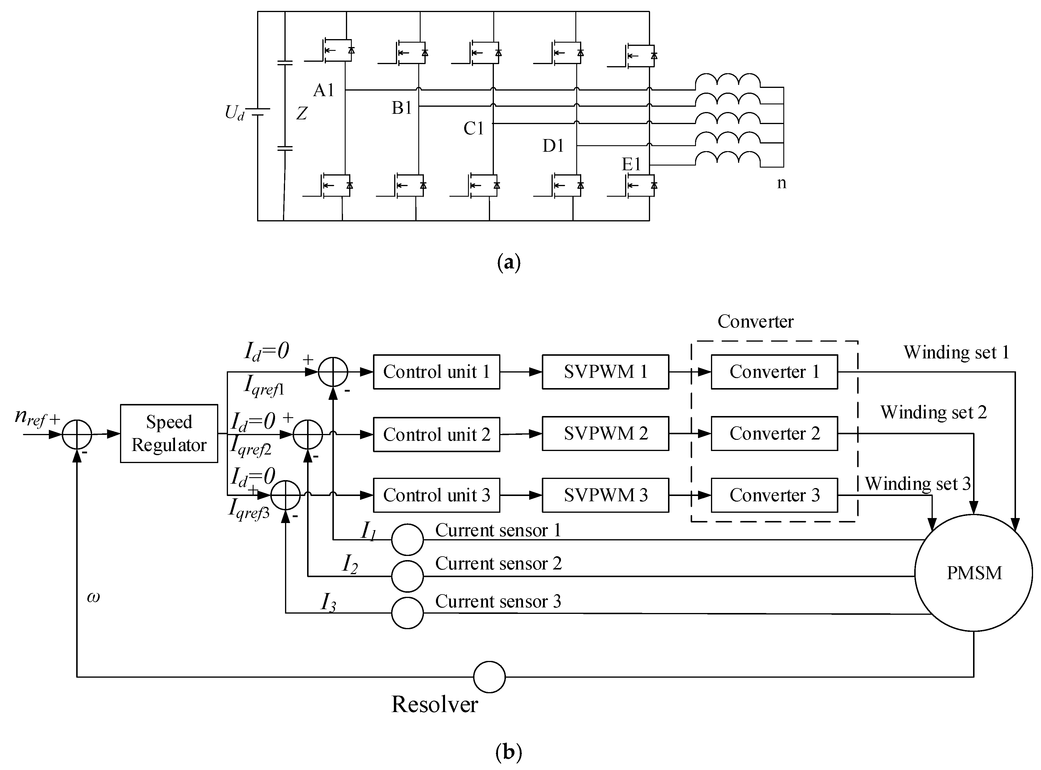
2. Asymmetric Winding Multiphase Motor and Its Model

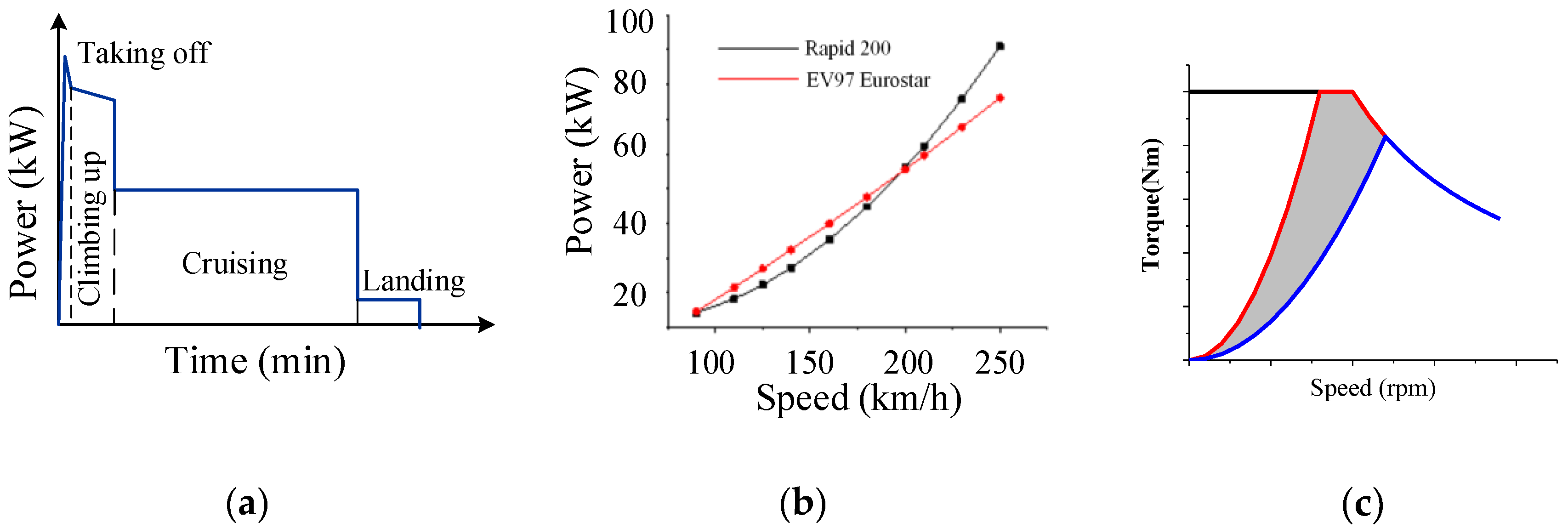
2.1. Work Area of Propulsion Motor

In electric aircrafts and ships, the motor drives the propeller to produce the thrust required for the propulsion system, for the propeller load, the output torque can be described as
T = ρ C T D 5 n 2
where ρ is the air density, CT is torque coefficient, D is propeller diameter, and n is propeller rotation speed.
When the propeller parameters are determined, the output torque of the propeller is proportional to the square of its speed. Output torque can be adjusted by changing propeller attitude angle. Typical power curves are as shown in (Figure 1a,b), taking all electric aircrafts Rapid 200 and EV97, for example. As ρ and CT change with altitude, motors work in shaded area in Figure 1c. As the air density varies with altitude and CT varies with flight attitude, the motor works on maximum power curve with lowest altitude and largest CT and minimum power curve with highest altitude and smallest CT. Long-term power may be only 15–20% of peak power, and the actual work area takes only a small part of the whole work area. In practical applications, such as all electric aircrafts, high power is only needed in the taking off stage, so for most of the time, the motor works at a low power cruising condition.
Under this condition, the motor cannot keep working at the highest efficiency area for a long time, which reduces system efficiency.
Therefore, if we can reduce motor copper loss and improve the efficiency of motor in a low power area, it will extend cruise range, even if the efficiency improves only a little. To achieve this goal, the efficiency of high speed and torque area can be partly sacrificed. Considering that the speed and power of electric drive and propulsion system vary greatly, the motor windings are divided into three sets, which have high efficiency in low, middle and high speed area, and their power is matched according to specific working conditions.

2.2. Matching Mode of Windings

Taking fifteen-phase motor as an example, the asymmetric winding multiphase motor structure is shown as Figure 2. The stator winding is divided into three sets of independent five-phase windings, and each set has an independent neutral point. The electric angle difference in a set is 72 degree and 12 degree between different sets. The three sets of windings have different numbers of turns per phase and sectional area.
In this paper, asymmetric winding means that the three sets of windings have different turns-in-series per-phase and cross-sectional area. Therefore, different sets of windings will produce different magnetomotive force and induced electromotive force when the motor works.
In an asymmetric winding multiphase motor, there are three matching modes for different sets of windings:
  • Equal torque mode: the three sets of windings have same rated torque but different rated speed;
  • Equal speed mode: the three sets of windings have same rated speed but different rated torque;
  • Equal power mode: the three sets of windings have same rated power but different rated speed and torque.
For the three matching modes, the relationship between the work area of each independent set of windings and the entire motor are shown in Figure 3. The motor has similar torque characteristic under different matching modes. Due to the presence of low rated speed winding, the peak power of motor decreases, but motor performance in low-speed area and high-speed areas can be optimized and the motor speed range improves.
Among the three matching modes, we exclude equal power mode first because it could not well fit both low speed and high speed area. Under propeller load, motor torque increases with speed, while in equal power matching, high speed winding has the lowest rated torque.
Aiming at the propeller load, this paper selects the equal torque matching and equal speed mode, and analyzes the optimal strategy of its efficiency, and compares it with the conventional motor.

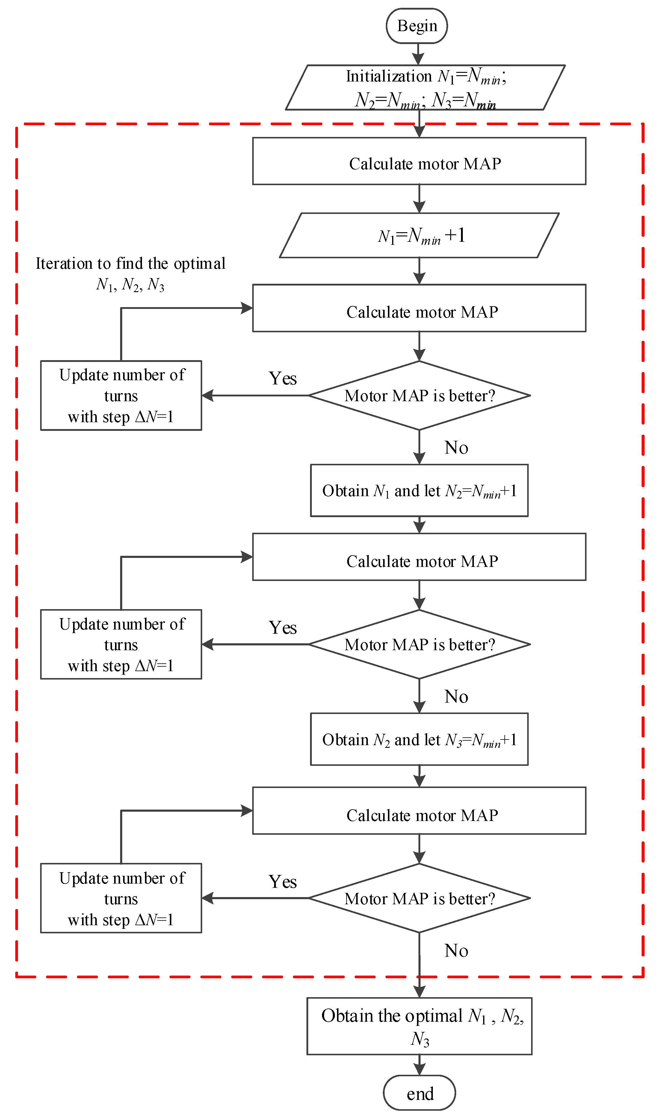
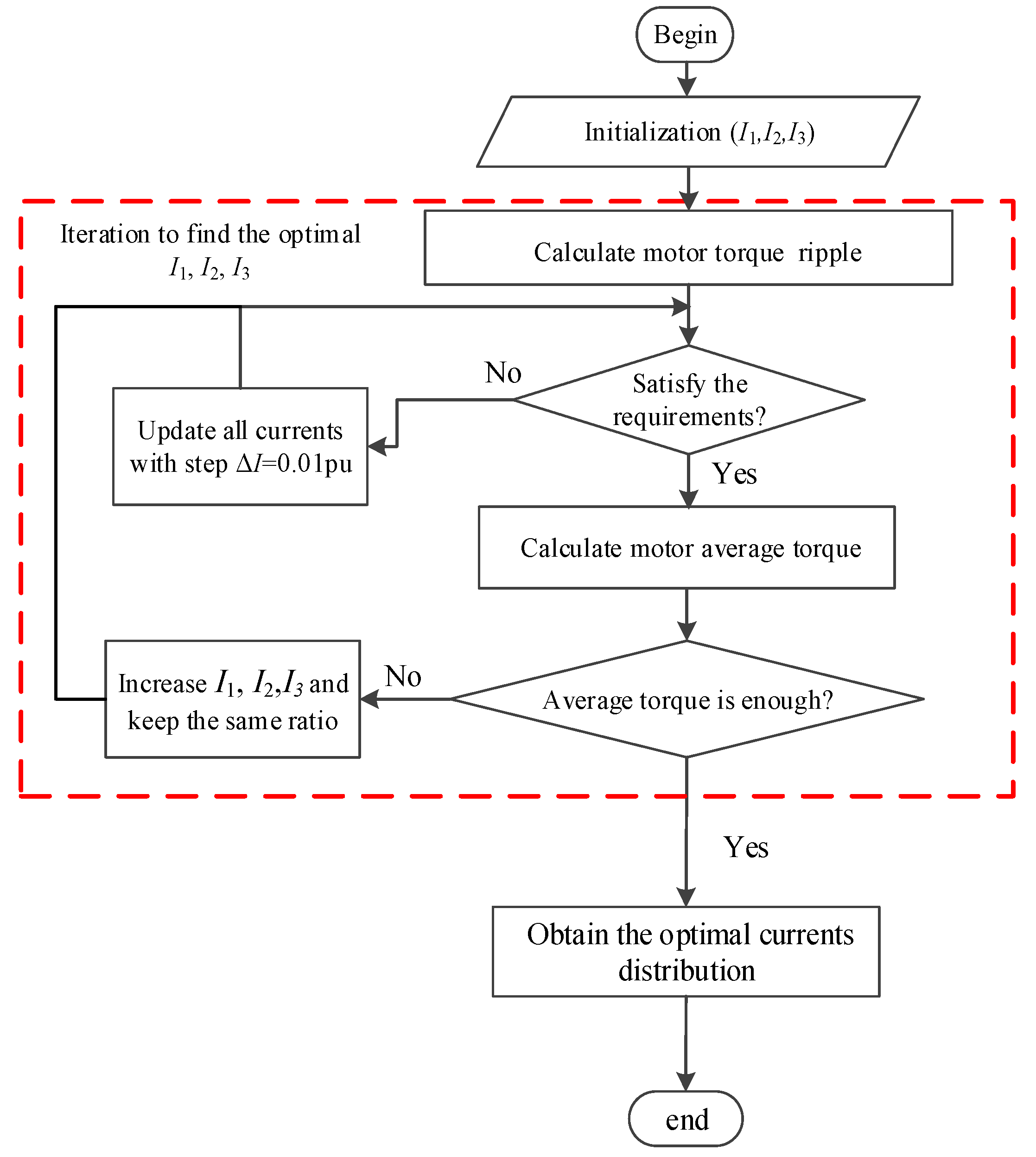
3. Efficiency Optimization Strategy of Asymmetric Winding

The electromagnetic torque of one set of winding can be described as
T e = 1 4 π K w n l N Q B ^ g A g I ^ cos φ
where Te is electromagnetic torque, Kw is winding factor, n l   is number of layers, N is number of turns per coil, Q is number of slots, Bg is peak air gap no load fundamental flux density, Ag is air gap area, I is peak current, cosφ is power factor
For the three sets of windings, their spatial structure is the same, so the winding factor, number of slots, number of winding layers and the magnetic field are the same, and the power factor is basically the same. Therefore, when principal dimension is selected, the area of the stator slot of the motor and fill factor remains unchanged. Thus, we can get
{ N 1 I 1 + N 2 I 2 + N 3 I 3 = F s S 1 + S 2 + S 3 = S
where Fs and S are magneto motive force and slot area, and N1, N2, N3 are number of turns per phase of each set of winding, I1, I2, I3 are peak phase current of each set of winding, S1, S2, S3 are coil cross-sectional area of each set of winding.
There are nine variables in Equation (3), which makes it difficult to obtain optimal parameters directly. Therefore, assume that N3, I3, S3 are determined, and the problem is simplified to equation with six variables, that is
{ N 1 I 1 + N 2 I 2 = F s S 1 + S 2 = S
let N2 = k1N1, I2 = k2I1, S2 = mS1, then we can get that
I 1 = F s N 1 ( 1 + k 1 k 2 ) , S 1 = S 1 + m
the winding resistance is
R 1 = ρ N 1 l S 1 / N 1 = ρ N 1 2 l S 1 , R 2 = ρ N 2 l S 2 / N 2 = ρ N 2 2 l S 2 , R 2 = k 1 2 R 1 / m ,
and the copper loss is
L o s s = I 1 2 R 1 + I 2 2 R 2 = I 1 2 R 1 ( 1 + k 1 2 k 1 2 m ) = F s 2 N 1 2 ( 1 + k 1 k 2 ) 2 ρ N 1 2 l ( 1 + m ) S ( 1 + k 1 2 k 2 2 m ) = ρ l F s 2 S [ 1 + m ( 1 + k 1 k 2 ) 2 m + k 1 2 k 2 2 m ]
Obviously, only when m = k1k2, there is a minimum
L o s s min = ρ l F s 2 S
The optimal condition of the motor efficiency is that copper loss of the two winding sets are the same. So, for three sets of windings, we can assume that N2 = N3, I2 = I3, S2 = S3,
{ N 1 I 1 + 2 N 2 I 2 = F s S 1 + 2 S 2 = S
let N2 = k1N1, I2 = k2I1, S2 = mS1, then we can get that
I 1 = F s 1 + 2 k 1 k 2 , S 1 = S 1 + 2 m , R 2 = k 1 2 R 1 / m
and the copper loss is
L o s s = I 1 2 R 1 + 2 I 2 2 R 2 = I 1 2 R 1 ( 1 + 2 k 1 2 k 1 2 m ) = ρ l F s 2 S [ 1 + 2 m ( 1 + 2 k 1 k 2 ) 2 m + 2 k 1 2 k 2 2 m ]
Obviously, only when m = k1k2, there is a minimum
L o s s min = ρ l F s 2 S
When three sets of winding work together, the motor has optimal efficiency when three sets of winding have same copper loss. In equal torque matching mode, each phase of stator winding produces same magneto motive force, that is N1I1 = N2I2 = N3I3, and the magnetic field distribution is equivalent to the symmetric winding. As a result, when each phase produces same torque, the motor naturally works in optimal efficiency state.

4. Matching of Winding Parameters

In order to verify the performance of the proposed motor structure, the electromagnetic simulation model of the motor is built, as well as the model of the symmetric winding motor.
In this paper, the prior target is to reduce total losses in a typical flight working condition, and the torque ripple is also taken into consideration. Firstly, the number of turns per coil should be calculated. In this step, we listed all available combinations (N1, N2, N3), and for each combination, we calculated the efficiency.
The motor model is 20 kW for a small all electric aircraft, of which the bus voltage is 270 V DC. In a typical flight profile, the motor has three main stages: taking off, climbing up and cruise. For symmetric winding motor and the equal speed winding motor, the winding is corresponding to cruise stage, as it lasts the longest time in flight profile. For asymmetric winding, the flow chart of winding matching is shown in Figure 4, the maximum and minimum speed is corresponding to taking off and cruise respectively. Thus, we can get required motor speed and torque from Figure 1, and then we get the minimum and maximum number of turns per coil Nmin and Nmax, corresponding to taking off and cruise. As taking off only lasts a few seconds, while climbing up and cruise take several hours, performance during cruise stage is mainly optimized. Therefore, we can exclude all combinations that two or more sets of winding have higher rated speed than that needed for climbing up. Among all available combination, we calculate the efficiency map and compare the peak efficiency and high efficiency area to pick up the best combination.
Finally, the winding configuration of the three motor structures is shown in Table 1. In the asymmetric winding motor, the number of series turns per phase confirms that the motor has enough peak speed and torque for taking off, and has high efficiency in the climbing up and cruise stage. In five phase windings, the line voltage of two phases is higher than that of three phase windings. Moreover, the voltage of DC bus in all electric aircraft is usually 270 V, which is lower than that of electric vehicles and ships, so the number of series turns per phase is relatively lower. In the equal torque winding, all windings have same rated torque and current density, as a result, all windings occupy the same slot area to get the same copper loss.

5. Simulation Analysis

After the winding matching, the simulation model is built with Ansoft Maxwell software to analyze the performance and loss, as shown in Figure 5. The overall motor construction is the same as a classic radial flux permanent magnet synchronous motors (PMSM), which has surface mounted permanent magnet rotor and fifteen-phase double-layer fractional slot concentrated winding. The stator core and rotor core are classic structure and all the coils distribute along the axis in classic form. The difference is that the fifteen-phase winding is divided into three sets of five-phase winding, and the three neutral points are independent. The three sets of windings have different number of turns and cross-sectional area, and therefore produce different magneto motive forces.
In Section 2.1, it has been shown that the motor torque is proportional to the rotating speed under the propeller load, so that the motor does not demand high field weakening ability, so surface mounted permanent magnet synchronous motor is adopted, with the slot/pole combination of 30/28. The winding arrangement of the motor is shown in Figure 6. Under such arrangement, the difference between adjacent phases of each set of winding is 72 degrees, while the difference between different sets is 12 degrees.
The converter structure and control topology of the motor are shown in Figure 7. Each individual set of winding is controlled by a five-phase five-bridge arm converter, as shown in Figure 7a. In order to enhance the fault tolerance ability, two capacitors are used and the central tap terminal Z is also lead out. When the capacitor fault occurs, central tap terminal Z will be connected with positive or negative terminal of the power supply to maintain the operation. The system control topology is shown as Figure 7b. Each set of windings is controlled by an independent five-phase converter and all the three sets of independent converters apply SVPWM method, and share the same DC power supply. As the three set of windings have different turns, they also have different rated speed and torque. According to the torque demand of the motor, the controller distributes the torque to three sets of windings, while rotor position is obtained through a resolver and sent to three control units synchronously. Then, the three converters generate the switch signal to control the IGBTs to supply current to the motor.

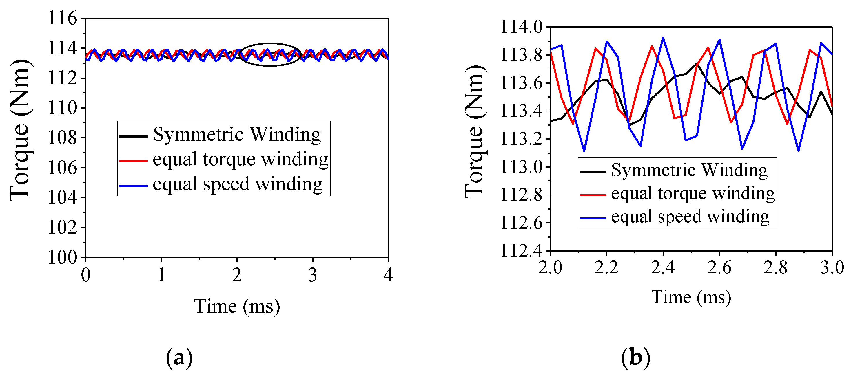
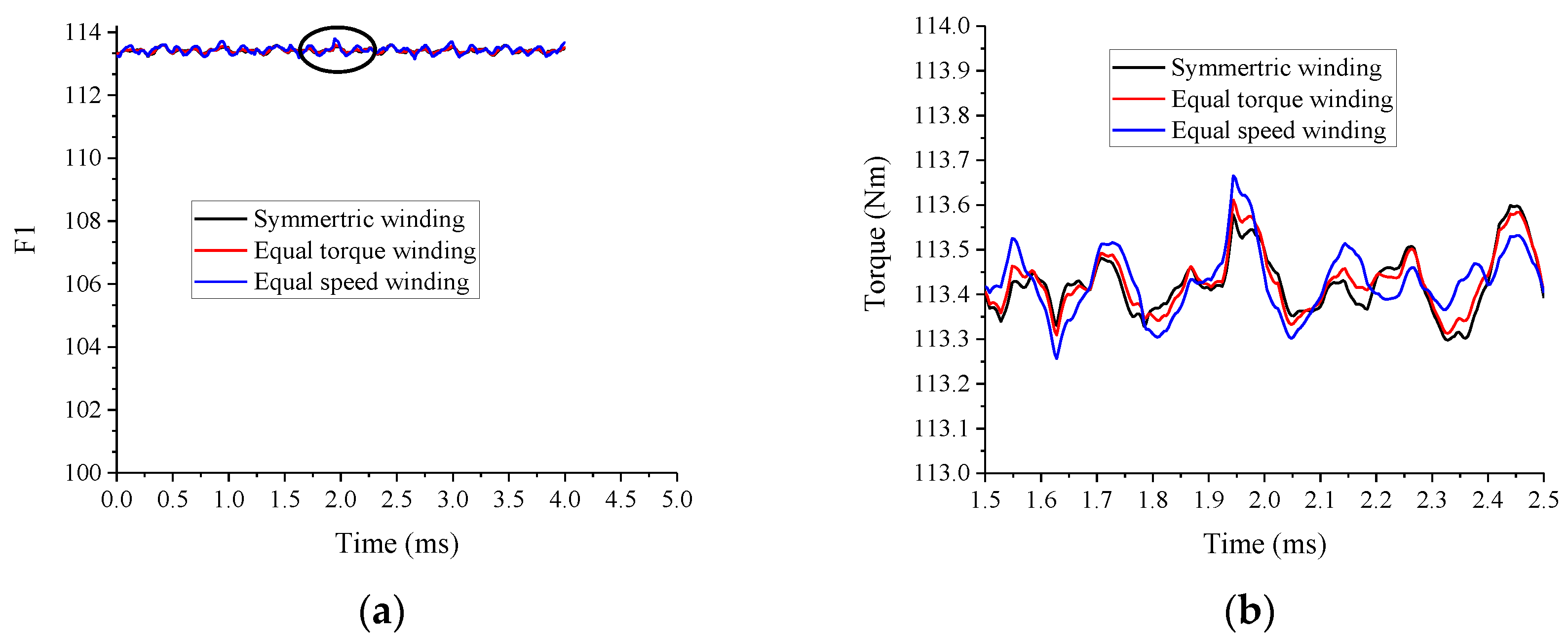
5.1. Motor Torque Characteristic Simulation

Figure 8 and Figure 9 are the comparison of the external characteristic and torque waveforms of symmetrical winding, equal torque asymmetrical winding and equal speed asymmetric winding motors. The winding parameters have been listed in Table 1. The three motors have same peak torque. In the equal speed winding motor, only the rated current and torque are changed, but the number of turns per coil is the same as symmetric winding motor, as a result, it has the same external characteristic as a symmetric winding motor. Moreover, in equal torque winding motor, as the three sets of windings have the same torque, the winding with high rated speed has higher power, and as a result, it expands peak speed of the motor. On the contrary, equal torque winding motor enter field-weakening state at a relatively lower speed, which decreases peak power.
On the torque waveform, the average torque of the three winding configurations is the same. The difference is that the torque ripple of the symmetrical winding is uniform and smaller, while the asymmetric winding has obvious larger torque ripple.

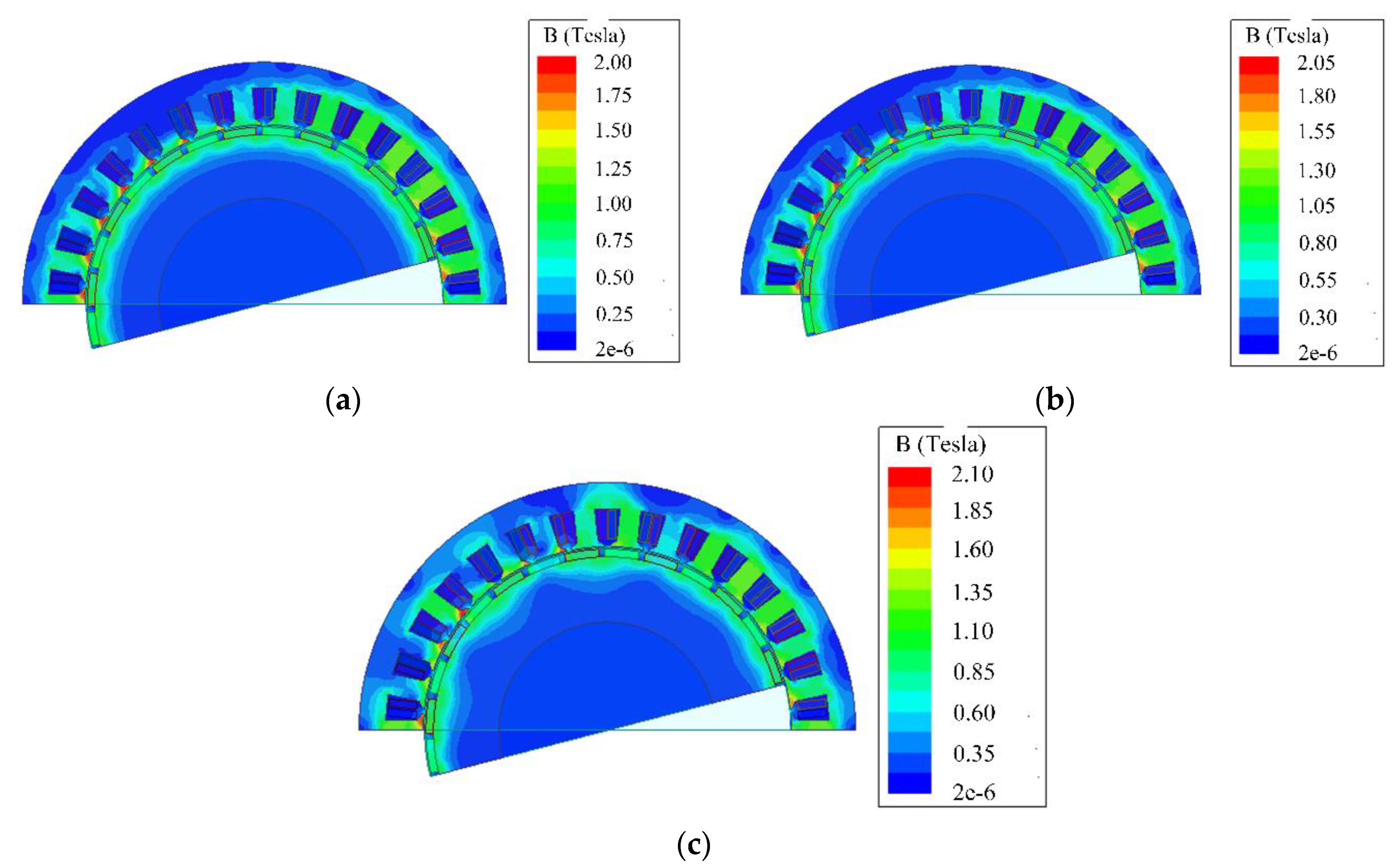
5.2. Optimization of Electromagnetic Design

The simulation results show that the torque ripple of asymmetrical winding motor is slightly higher than that of symmetrical winding motor. For the application background of all electric aircrafts in this paper, it can be seen from Equation (1) that the torque ripple will also affect the speed of the motor, and then affect flight stability. Therefore, although the amplitude of torque ripple is limited, it should be optimized as far as possible.
Because the number of turns per phase and rated current of three sets of windings are different, while the working speed of the motor is fixed, the power factor of three sets of windings are slightly different at the same speed. As a result, when the current of three sets of windings is distributed according to the optimal efficiency strategy in Section 3, the armature reaction of each set of windings is not completely consistent. Therefore, the harmonics of rotating magneto motive force and the torque ripple of the motor increases slightly. In equal speed asymmetric winding motor, the windings have equal turns but different current, therefore, the magneto motive force is also unequal, which results in higher harmonics and torque ripple.
In order to optimize the output torque of the motor, it is necessary to adjust the winding parameters of the motor. By adjusting the cross-sectional area and rated current of each set of windings, the magneto motive force of each winding tends to be the same. As a result, torque ripple decreases. However, it should be noted that the actual purpose of the asymmetric winding motor is to reduce the loss. Therefore, while optimizing the winding, the loss of the motor should be kept constant or increased only minimally.
Figure 10 shows the flow chart of torque optimization. The target of the optimization is to reduce the torque ripple and keep the efficiency unchanged. Firstly, the rated current of each winding is initialized. Then, we fix the current of one set of windings, and change the current in the other two sets of windings to obtain the ratio of rated current with minimum torque ripple. Then, keep the current ratio and adjust the current amplitude to make the output torque meet the requirement. Finally, the optimal rated current of three sets of windings is obtained by iteration. Then, according to the rated current, the cross-section area and resistance of each set of windings are optimized, and the optimal cross-section area and resistance of each set of windings are obtained.
After optimization, the winding parameters and torque waveforms of each set of motor are shown in Table 2 and Figure 11. The left is a torque waveform of the three kinds of windings, while the right is local enlarged drawing, which shows the waveform from 1.5 ms to 2.5 ms more clearly. It can be seen that, after optimization, compared with that in Figure 9, the torque ripple of the asymmetrical winding decreases from 0.6 Nm to 0.4 Nm, and is basically the same with symmetric winding, which shows that the optimized winding parameters effectively reduces the torque ripple.

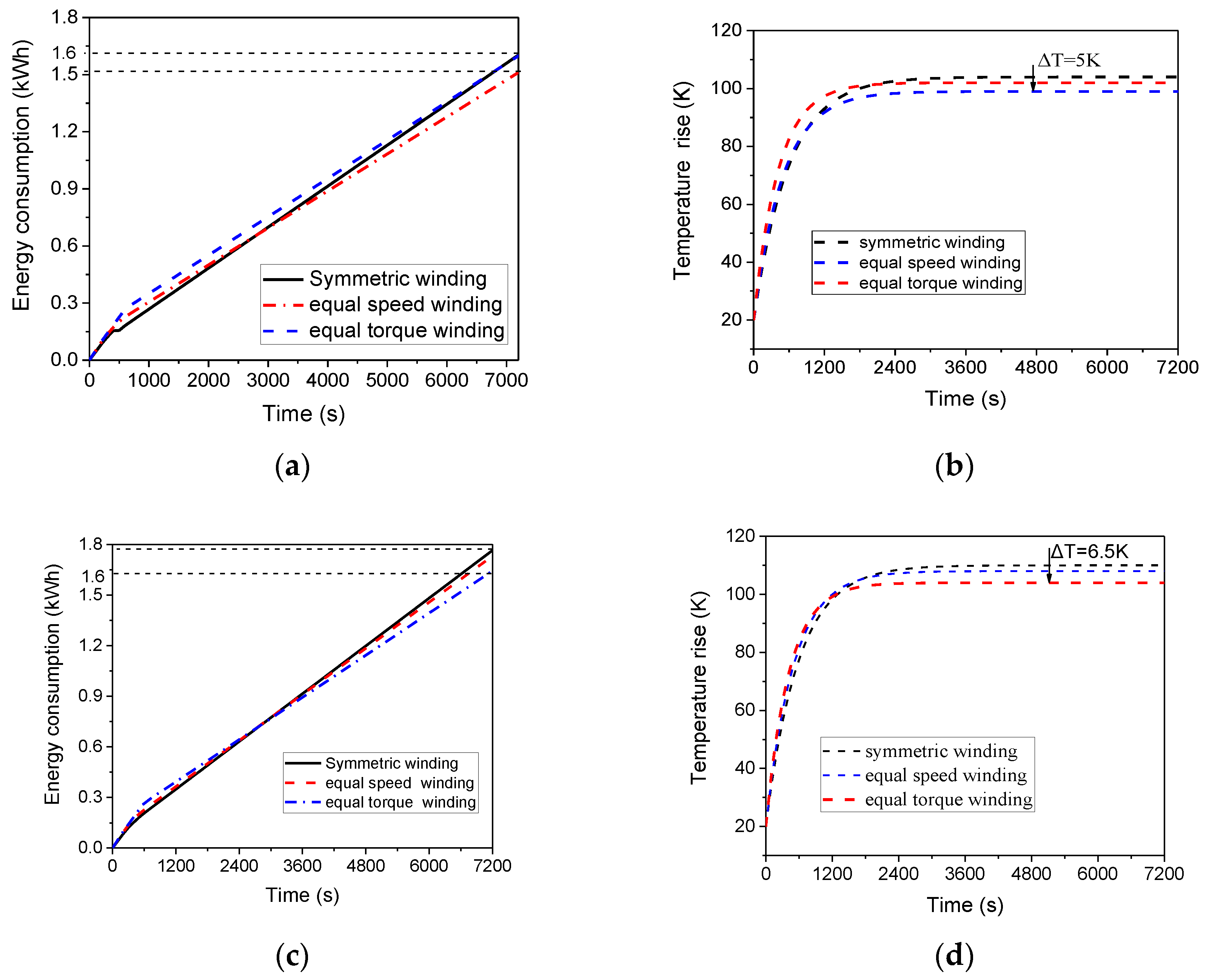
5.3. Motor Efficiency Simulation

This section will present a comparison of the efficiency map of the three motors. Because the motor has three independent sets of windings, so, at each working point, the motor has three working modes: one set of windings operation, two sets of windings operation and three sets of windings operation. In the asymmetric winding motor, as the three sets of windings are different from each other, motor performance varies with the choice of working windings, so there are totally seven conditions. Figure 12 shows the motor magnetic field distribution when the motor works in all windings, two sets of windings and one set of windings under the same torque. Under different working modes, the distribution of stator and rotor magnetic field is obviously different, which will also affect the losses and efficiency of the motor. Therefore, in order to obtain the optimal efficiency characteristics, it is necessary to compare the efficiency of different working modes at the same working point. In the map analysis of motor, the working strategy adopted is to detect the highest efficiency of the three working modes at each working point and compare them to get the best efficiency work mode. This efficiency strategy can ensure that the motor is always working in the best state of efficiency.
In this efficiency optimization strategy, one problem is the dynamic process of the motor. When one or more windings are switched off or switched on, the torque of the motor takes a dynamic process to achieve a new steady state. During this process, the value current and torque of the motor will be higher than the final steady value, which leads to the increase of copper loss. Moreover, the magnetic field of the motor also changes in the process, which results in the increase of iron loss. Therefore, the dynamic process causes the increase of loss in a short time, especially when the winding is switched on. Therefore, when the working state of the windings is continuously switched in a short time, the loss reduction obtained by the efficiency optimization strategy may not be able to compensate for the increased loss in the dynamic process. In order to avoid this case, a time threshold is set in the efficiency optimization strategy. The state switching is carried out only when a new state duration exceeds the threshold value.
The efficiency map figure of the motor is the efficiency contour map of different working points, which shows the motor efficiency distribution. In order to get the efficiency map, firstly, 20 speed points are taken evenly from 0 to the peak working speed, and the peak torques of each point are calculated. Then 20 torque points are taken evenly from 0 to the peak torque, so that 400 working points are obtained. According to the optimization strategy determined in Figure 8, the efficiency of these 400 working points is calculated, and based on this, the efficiency of other work points in the work area is obtained by interpolation, and the efficiency map is drawn.
As shown in Figure 13, the maximum efficiency of symmetric and asymmetric winding motors is basically the same, but the efficiency of asymmetrical winding motor in low torque region is slightly higher than that of symmetrical winding motor. While in the region between rated speed of the low speed winding and medium speed winding, the symmetrical winding motor is more efficient, because the low speed winding is in the state of field weakening. In the working area of all electric aircraft motors, the equal torque winding motor and the equal speed winding motor have a larger area, in which the efficiency is higher than 92%.
For propeller propulsion system such as aircrafts and ships, the torque is proportional to the speed, and the required power of cruise is far less than the peak power, and the motor works mainly in a light load area, where the efficiency of the asymmetrical winding motor is higher than that of the symmetrical winding motor. Although the symmetrical winding motor is more efficient in high speed and large torque areas, because the working time at low speed and low torque is obviously longer than that of high speed and large torque, the total loss of the asymmetrical winding motor in a working cycle is lower, and it has better adaptability to the actual working condition.
In order to compare the loss, efficiency and temperature rise of asymmetrical winding motor and symmetrical winding motor in actual operation, the loss and temperature rise of motor in typical flight conditions and variable speed flight conditions are analyzed, as shown in Figure 14.
Figure 14a,b show the energy consumption and temperature rise curves of symmetrical winding, asymmetrical windings with equal speed and an asymmetrical winding with equal torque under typical operating conditions. In typical working condition, the range of motor speed and power changes is very small in cruise stage, which basically maintains a certain value. In this case, the working speed of equal speed asymmetric winding motor is close to its rated speed, and compared with the symmetrical winding, the rated torque and working torque of two sets of windings are closer, thus, more windings work in a high efficiency area. As a result, loss and temperature rise are lower after a drive cycle. Compared with the symmetric winding motor, the total loss decreases by 5% and temperature rise decreases by 5K.
Figure 14c,d show the energy consumption and temperature rise curves of symmetrical windings, asymmetrical windings with equal speed and asymmetrical windings with equal torque when cruising speed changes. In this case, the working speed and power of the motor vary widely, and the efficiency of the asymmetrical winding motor with equal torque changes more smoothly in the working range. The efficiency of the motor in high speed and low speed area is higher, so the final loss reduces by 10% and temperature rise reduces by 6K.
It can also be seen from Figure 13 that the asymmetrical winding motor is more efficient in the cruise stage. Therefore, for similar conditions, if the cruise time is prolonged, the system will save more energy. For example, ships driven by propellers may cruise at a constant speed for hours or even days, and more energy can be saved by using asymmetric winding motors.

5.4. Size and Cost of the Motor System

In all electric aircrafts, the weight, volume and cost of the motor propulsion system should also be considered. In the same aircraft, larger weight will not only reduce the load, but also force the aircraft to cruise at a faster speed, to improve the lift generated by the wings, which results in more losses.
Table 3 lists the motor power, weight and power density of several different all electric aircrafts, and compares them with the motor designed in this paper. It can be seen that the actual motor power density is usually 1.2–1.5 kW/kg, and some motors can reach more than 2 kW/kg. The power density of the motor designed in this paper is 1.22 kW/kg, which is in the normal range. Therefore, the volume of the motor proposed in this paper is the same as that of the traditional motor.
In the converter, the proposed motor structure needs 30 IGBTs, while the conventional three-phase motor with three-phase half bridge or three-phase four-bridge arm, only needs 6 IGBTs. The increase of IGBT quantity will increase the volume and cost of the converter. Yet on the other hand, due to the larger number of phases, the current of each phase is reduced, as well as the rated current of IGBTs, which partially inhibits the increase of cost. Finally, the volume of the converter increases by about 12%, the weight increases by 5 kg, and the cost increases by 500 euros. The increase of the total amount will increase the energy consumption of the system by 1.6%. However, in the typical flight conditions, the motor and converter system described in this paper still has advantages in energy consumption, taking the increased energy consumption due to the weight increase into consideration.

6. Conclusions

This paper proposes a multiphase motor structure for an electric drive system, which stator winding consists of three independent windings. The three independent windings have different coil turns and current. Torque characteristic and efficiency characteristic are analyzed among three kinds of winding: classic symmetric winding, equal torque asymmetric winding and equal speed asymmetric winding. The proposed motor has the same peak torque with conventional motor because of the same size. However, the asymmetric winding motors have different characteristics. The equal speed winding has same external characteristic with symmetric winding, while equal torque winding has smaller constant torque area because of a set of windings with lower rated speed. Moreover, although the proposed equal torque winding motor has a lower peak power, it has a set of windings with higher rated speed, which leads to better performance in high speed area, thus expands speed range and improves high speed characteristic. Compared to classic motor, because of windings that have lower rated torque or speed, the proposed asymmetric winding motor has better performance in low-speed and low-torque area. As all electric aircrafts take much more time in cruise than that in take-off and climbing, and cruise power is lower, so in most time, the propulsion motor works in low-speed and low-torque area. As a result, the asymmetric winding motor has lower losses in a typical drive cycle for propeller load, although it has lower efficiency in the field weakening area. Moreover, lower losses also lead to lower temperature increases, which is beneficial to motor reliability. In addition, the cruise range also extends because of lower losses.

Author Contributions

Conceptualization, S.C.; Formal analysis, T.Z.; Validation, Y.C.; Writing—original draft, T.Z.; Writing—review and editing, B.D. All authors have read and agreed to the published version of the manuscript.

Funding

This research was funded by National Natural Science Foundation of China, grant number 51577035.

Conflicts of Interest

The authors declare no conflict of interest.

References

  1. Kietley, J.L.; Banerjee, A.; Englebretson, S. Motors for Ship Propulsion. Proc. IEEE 2015, 103, 2320–2332. [Google Scholar] [CrossRef]
  2. Thongam, J.S.; Tarbouchi, M.; Okou, A.F.; Bouchard, D.; Beguenane, R. Trend in naval ship Propulsion drive motor technology. In Proceedings of the IEEE Electrical Power and Energy Conference, Halifax, NS, Canada, 21–23 August 2013; pp. 1–5. [Google Scholar]
  3. Soghomonian, Z.; Prousalidis, J.M.; Kanellos, F.; Dallas, S.E.; Spathis, D.; Kourmpelis, T.; Tsekouras, G. The role of efficiency of electric machinery on green shipping. In Proceedings of the International Conference on Electrical Machines, Lausanne, Switzerland, 4–7 September 2016; pp. 2968–3974. [Google Scholar]
  4. Wang, F.; Zhang, Z.; Ericsen, T.; Raju, R.; Burgos, R.; Boroyevich, D. Advances in Power Conversion and Drives for Shipboard Systems. Proc. IEEE 2015, 103, 2285–2311. [Google Scholar] [CrossRef]
  5. Park, S.J.; Song, J.H.; Choi, H.Y.; Lee, M.L.; Kong, Y.K.; Bin, J.G. A study on design of inverter for multi-phase brushless DC ship propulsion motor. In Proceedings of the 2010 IEEE Vehicle Power and Propulsion Conference, Lille, France, 1–3 September 2010; pp. 1–5. [Google Scholar]
  6. Choi, H.Y.; Park, S.J.; Lee, M.L.; Kong, Y.K.; Bin, J.G. Efficiency compensation of multi-phase PM motor with redundant structure. In Proceedings of the XIX International Conference on Electrical Machines—ICEM, Rome, Italy, 6–8 September 2010; pp. 1–3. [Google Scholar]
  7. Moinoddin, S.; Iqbal, A.; Abu-Rub, H.; Khan, M.R.; Ahmed, S.M. Three-Phase to Seven-Phase Power Converting Transformer. IEEE Trans. Energy Convers. 2012, 27, 757–766. [Google Scholar] [CrossRef]
  8. Liu, Z.; Peng, L.; Li, Y.; Zheng, Z. Vector control of fixed joint double fifteen-phase induction motors system with propeller load. In Proceedings of the 15th European Conference on Power Electronics and Applications (EPE), Lille, France, 2–6 September 2013; pp. 1–9. [Google Scholar]
  9. Choi, H.; Jasinski, M.; Liu, J. Novel permanent magnet systems for high efficiency electric ships. In Proceedings of the IEEE Electric Ship Technologies Symposium (ESTS), Alexandria, Egypt, 21–24 June 2015; pp. 219–223. [Google Scholar]
  10. Heising, C.; Staudt, V.; Steimel, A. Optimized energy-efficient drive system for ship propulsion. In Proceedings of the IEEE Electric Ship Technologies Symposium, Alexandria, Egypt, 10–13 April 2011; pp. 292–295. [Google Scholar]
  11. Frank, M.; van Habelt, P.; Kummeth, P.; Massek, P.; Nick, W.; Rothfischer, H.; Schmidt, H.; Wacker, B.; Neumuller, H.W.; Nerowski, G.; et al. High-Temperature Superconducting Rotating Machines for Ship Applications. IEEE Trans. Appl. Supercond. 2006, 16, 1465–1468. [Google Scholar] [CrossRef]
  12. Yanamoto, T.; Izumi, M.; Umemoto, K.; Oryu, T.; Murase, Y.; Kawamura, M. Load Test of 3-MW HTS Motor for Ship Propulsion. IEEE Trans. Appl. Supercond. 2017, 27, 5204305. [Google Scholar] [CrossRef]
  13. Baik, S.; Kwon, Y.; Park, S.; Kim, H. Performance Analysis of a Superconducting Motor for Higher Efficiency Design. IEEE Trans. Appl. Supercond. 2013, 23, 20–25. [Google Scholar]
  14. Park, S.W.; Park, H.S.; Moon, J.J. Maximum efficiency control method in 7-phase BLDC motor by changing the number of the excited phase windings. In Proceedings of the Energy Conversion Congress and Exposition, Milwaukee, WI, USA, 18–22 September 2016; pp. 1–6. [Google Scholar]
  15. Debbou, M.; Damdoum, A.; Pietrzak-David, M. Optimal sliding mode control for DFIM electric marine thruster. In Proceedings of the International Conference on Electrical Systems for Aircraft, Railway, Ship Propulsion and Road Vehicles & International Transportation Electrification Conference (ESARS-ITEC), Toulouse, France, 2–4 November 2016; pp. 1–6. [Google Scholar]
  16. Bolvashenkov, I.; Herzog, H.G. Use of Stochastic Models for Operational Efficiency Analysis of Multi Power Source Traction Drives. In Proceedings of the Second International Symposium on Stochastic Models in Reliability Engineering, Life Science and Operations Management, Beer-Sheva, Israel, 15–18 February 2016; pp. 124–130. [Google Scholar]
  17. Romeo, G.; Moraglio, I.; Novarese, C. ENFICA-FC: Preliminary Survey & Design of 2-Seat Aircraft Powered by Fuel Cells Electric Propulsion. In Proceedings of the 7th AIAA Aviation Technology, Integration and Operations Conference, Belfast, UK, 18–20 September 2014; pp. 202–216. [Google Scholar]
  18. Cao, W.; Mecrow, B.C.; Atkinson, G.J. Overview of Electric Motor Technologies Used for More Electric Aircraft (MEA). IEEE Trans. Ind. Electron. 2012, 59, 3523–3531. [Google Scholar]
  19. Tomažič, T.; Plevnik, V.; Veble, G. Pipistrel Taurus G4: On Creation and Evolution of the Winning Aeroplane of NASA Green Flight Challenge 2011. Stroj. Vestn. J. Mech. Eng. 2011, 57, 869–878. [Google Scholar] [CrossRef] [Green Version]
  20. Sarlioglu, B.; Morris, C. More Electric Aircraft-Review, Challenges and Opportunities for Commercial Transport Aircraft. IEEE Trans. Transp. Electrif. 2015, 1, 54–64. [Google Scholar] [CrossRef]
  21. Yeoh, S.S.; Gao, F.; Bozhko, S.; Asher, G. Control Design for PMM-based Starter Generator System for More Electric Aircraft. In Proceedings of the 16th Conference on Power Electronics and Applications, EPE’14-ECCE Europe, Lappeenranta, Finland, 26–28 August 2014; pp. 1–10. [Google Scholar]
  22. Zhao, X.; Guerrero, J.M.; Wu, X. Review of Aircraft Electric Power Systems and Architectures. In Proceedings of the 2014 IEEE International Energy Conference (ENERGYCON), Cavtat, Croatia, 13–16 May 2014; pp. 949–953. [Google Scholar]
  23. Zhao, T.; Wu, S.; Cui, S. Multiphase PMSM with Asymmetric Windings for More Electric Aircraft. IEEE Trans. Transp. Electrif. 2020. [Google Scholar] [CrossRef]
Figure 1. Motor working condition (a) typical working condition; (b) typical power curve; (c) working area.
Energies 13 03765 g001
Figure 2. Winding distribution of proposed motor [23].
Energies 13 03765 g002
Figure 3. External characteristic of different winding match modes; (a) symmetric winding; (b) Equal torque matching mode; (c) Equal speed matching mode; (d) Equal power matching mode [23].
Energies 13 03765 g003
Figure 4. Flow chart of winding matching.
Energies 13 03765 g004
Figure 5. Motor simulation model; (a) radial 2D construction, (b) 3D construction [23].
Energies 13 03765 g005
Figure 6. Motor winding layout.
Energies 13 03765 g006
Figure 7. Converter and control topology of the motor; (a) converter structure of each single set; (b) system control topology.
Energies 13 03765 g007
Figure 8. External characteristic curve of two motors.
Energies 13 03765 g008
Figure 9. Torque waveform of two motors. (a) entire waveform.; (b) local enlarged drawing.
Energies 13 03765 g009
Figure 10. Winding parameter optimization flow chart [23].
Energies 13 03765 g010
Figure 11. Torque curve after optimization. (a) entire waveform; (b) local enlarged drawing.
Energies 13 03765 g011
Figure 12. Magnetic field of the motor under different working modes, (a) all windings; (b) two sets of windings; (c) one set of windings.
Energies 13 03765 g012
Figure 13. Efficiency map figure of two motors (a) symmetric winding (b) equal torque asymmetric winding. (c) equal speed asymmetric winding [23].
Energies 13 03765 g013
Figure 14. Energy consumption and temperature rise of two motors; (a) motor energy consumption under typical cycle; (b) motor temperature rise under typical cycle; (c) energy consumption under variable speed; (d) motor temperature rise under variable speed [23].
Energies 13 03765 g014
Table 1. Motor design parameters.
ParametersEqual Torque WindingEqual Speed WindingSymmetric Winding
DC voltage270 V270 V270 V
Rated speed1500/2000/2500 rpm2000 rpm2000 rpm
Rated torque120 Nm120 Nm120 Nm
Winding 124 turns, 20 A32 turns, 20 A32 turns, 15 A
Winding 232 turns, 15 A32 turns, 15 A32 turns, 15 A
Winding 340 turns, 12 A32 turns, 10 A32 turns, 15 A
Table 2. Motor winding parameters optimization results.
ParametersEqual Torque WindingEqual Speed Winding
Rated speed1600/2000/2500 rpm2000 rpm
Rated torque120 Nm120 Nm
Winding 112 turns, 20.8 A16 turns, 18.3 A
Winding 216 turns, 14.7 A16 turns, 15.4 A
Winding320 turns, 11.8 A16 turns, 11.3 A
Table 3. Comparison of conventional all electric aircraft motors and the proposed motor.
MotorPower (kW)Weight (kg)Power Density (kw/kg)
Antares 20E42291.45
Rapid 20046381.21
Diamond HK3630410.75
Taurus Electro40311.29
Taurus G23012.82.34
E-Genius58272.15
Designed in this paper2016.41.22

