Common-Mode Reduction SVPWM for Three-Phase Motor Fed by Two-Level Voltage Source Inverter


Abstract
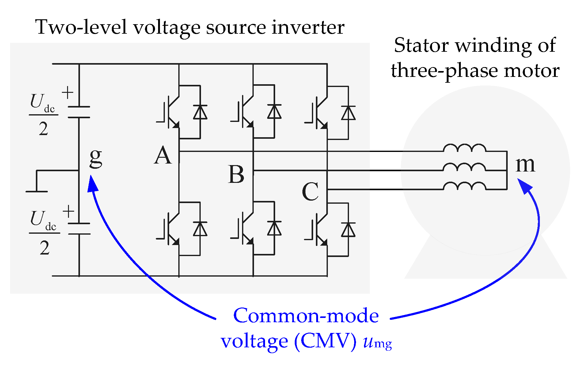
1. Introduction
2. Common-Mode Reduction SVPWM
2.1. Common-Mode Voltage Values of Eight Basic Vectors
2.2. SVPWM by Only Using Three Non-Zero Vectors
2.3. Common-Mode Reduction SVPWM
3. Simulations and Experiments
3.1. Simulation Results
3.2. Experimental Results
4. Conclusions
Author Contributions
Funding
Conflicts of Interest
References
- Wu, B.; Narimni, M. High-Power Converters and AC Drives, 2nd ed.; John Wiley & Sons: Hoboken, NJ, USA, 2017; pp. 1–4. ISBN 978-1-119-15603-1. [Google Scholar]
- Filizadeh, S. Electric Machines and Drives: Principles, Control, Modeling, and Simulation; CRC Press: Boca Raton, FL, USA, 2013; pp. 181–185. ISBN 978-1-439-85807-3. [Google Scholar]
- Huang, Y.; Xu, Y.; Li, Y.; Yang, G.; Zou, J. PWM frequency voltage noise cancelation in three-phase VSI using the novel SVPWM strategy. IEEE Trans. Power Electron. 2018, 10, 8596–8606. [Google Scholar] [CrossRef]
- Che, H.; Zhao, H. Review on pulse-width modulation strategies for common-mode voltage reduction in three-phase voltage-source inverters. IET Power Electron. 2016, 14, 2611–2620. [Google Scholar]
- Morris, C.T.; Han, D.; Sarlioglu, B. Reduction of common mode voltage and conducted EMI through three-phase inverter topology. IEEE Trans. Power Electron. 2017, 3, 1720–1724. [Google Scholar] [CrossRef]
- Han, D.; Lee, W.; Li, S.; Sarlioglu, B. New method for common mode voltage cancellation in motor drives: Concept, realization, and asymmetry influence. IEEE Trans. Power Electron. 2018, 2, 1188–1201. [Google Scholar] [CrossRef]
- Jiang, D.; Shen, Z.; Wang, F. Common-mode voltage reduction for paralleled inverters. IEEE Trans. Power Electron. 2018, 5, 3961–3974. [Google Scholar] [CrossRef]
- Robles, E.; Fernandez, M.; Ibarra, E.; Andreu, J.; Kortabarria, I. Mitigation of common mode voltage issues in electric vehicle drive systems by means of an alternative AC-decoupling power converter topology. Energies 2019, 17, 3349. [Google Scholar] [CrossRef]
- Jayaraman, K.; Kumar, M. Design of passive common-mode attenuation methods for inverter-fed induction motor drive with reduced common-mode voltage PWM technique. IEEE Trans. Power Electron. 2020, 3, 2861–2870. [Google Scholar] [CrossRef]
- Takahashi, S.; Ogasawara, S.; Takemoto, M.; Orikawa, K.; Tamate, M. Common-mode voltage attenuation of an active common-mode filter in a motor drive system fed by a PWM inverter. IEEE Trans. Ind. Appl. 2019, 3, 2721–2730. [Google Scholar] [CrossRef]
- Huang, Y.; Xu, Y.; Zhang, W.; Zou, J. Hybrid RPWM technique based on modified SVPWM to reduce the PWM acoustic noise. IEEE Trans. Power Electron. 2019, 6, 5667–5674. [Google Scholar] [CrossRef]
- Guo, L.; Jin, N.; Gan, C.; Luo, K. Hybrid voltage vector preselection-based model predictive control for two-level voltage source inverters to reduce the common-mode voltage. IEEE Trans. Ind. Electron. 2020, 6, 4680–4691. [Google Scholar] [CrossRef]
- Jiang, W.; Wang, P.; Ma, M.; Wang, J.; Li, J.; Li, L.; Chen, K. A novel virtual space vector modulation with reduced common-mode voltage and eliminated neutral point voltage oscillation for neutral point clamped three-level inverter. IEEE Trans. Ind. Electron. 2020, 2, 884–894. [Google Scholar] [CrossRef]
- Jin, T.; Guo, J.; Mohamed, M.A.; Wang, M. A novel model predictive control via optimized vector selection method for common-mode voltage reduction of three-phase inverters. IEEE Access. 2019, 7, 95351–95363. [Google Scholar] [CrossRef]
- Cetin, N.O.; Hava, A.M. Interaction between the filter and PWM units in the sine filter configuration utilizing three-phase AC motor drives employing PWM inverters. In Proceedings of the IEEE Energy Conversion Congress & Exposition, Atlanta, GA, USA, 12–16 September 2010; pp. 2592–2599. [Google Scholar]
- Ün, E.; Hava, A.M. A near-state PWM method with reduced switching losses and reduced common-mode voltage for three-phase voltage source inverters. IEEE Trans. Ind. Appl. 2009, 2, 782–793. [Google Scholar] [CrossRef]
- Tian, K.; Wang, J.; Wu, B.; Xu, D.; Cheng, Z.; Zargari, N.R. A virtual space vector modulation technique for the reduction of common-mode voltages in both magnitude and third-order component. IEEE Trans. Power Electron. 2016, 1, 839–848. [Google Scholar] [CrossRef]
- Huang, J.; Li, K. Suppression of common-mode voltage spectral peaks by using rotation reverse carriers in sinusoidal pulse width modulation three-phase inverters with CFM. IET Power Electron. 2020, 6, 1246–1256. [Google Scholar] [CrossRef]
- Zheng, J.; Rong, F.; Li, P.; Huan, S.; He, Y. Six-phase SVPWM with common-mode voltage suppression. IET Power Electron. 2018, 15, 2461–2469. [Google Scholar] [CrossRef]
- Abu-Rub, H.; Iqbal, A.; Guzinski, J. High Performance Control of AC Drives with MATLAB/Simulink Models; John Wiley & Sons: Hoboken, NJ, USA, 2012; pp. 72–78. ISBN 978-0-470-97829-0. [Google Scholar]
- Gao, H.; Wu, B.; Xu, D.; Pande, M.; Aguilera, R.P. Common-mode-voltage-reduced model-predictive control scheme for current-source-converter-fed induction motor drives. IEEE Trans. Power Electron. 2017, 6, 4891–4904. [Google Scholar] [CrossRef]
- Dai, J.; Li, G.; Hu, C. Study on a new method to eliminate the common-mode voltage based on improved SHEPWM. In Proceedings of the IEEE 10th Conference on Industrial Electronics and Applications (ICIEA), Auckland, New Zealand, 15–17 June 2015; pp. 1633–1636. [Google Scholar]
- Tan, B.; Gu, Z.; Shen, K.; Ding, X. Third harmonic injection SPWM method based on alternating carrier polarity to suppress the common mode voltage. IEEE Access. 2019, 7, 9805–9816. [Google Scholar] [CrossRef]


| V0 | V1 | V2 | V3 | V4 | V5 | V6 | V7 |
|---|---|---|---|---|---|---|---|
| −Udc/2 | −Udc/6 | Udc/6 | −Udc/6 | Udc/6 | −Udc/6 | Udc/6 | Udc/2 |
| Sectors | The First Vector Vx | The Second Vector Vy | The Third Vector Vz | |
|---|---|---|---|---|
| S1″ | 0° ≤ θ < 30° | V5 | V1 | V3 |
| 30° ≤ θ < 60° | V1 | V3 | V5 | |
| S2″ | 0° ≤ θ < 30° | V6 | V2 | V4 |
| 30° ≤ θ < 60° | V2 | V4 | V6 | |
| S3″ | 0° ≤ θ < 30° | V1 | V3 | V5 |
| 30° ≤ θ < 60° | V3 | V5 | V1 | |
| S4″ | 0° ≤ θ < 30° | V2 | V4 | V6 |
| 30° ≤ θ < 60° | V4 | V6 | V2 | |
| S5″ | 0° ≤ θ < 30° | V3 | V5 | V1 |
| 30° ≤ θ < 60° | V5 | V1 | V3 | |
| S6″ | 0° ≤ θ < 30° | V4 | V6 | V2 |
| 30° ≤ θ < 60° | V6 | V2 | V4 | |
| Parameters | Values | Parameters | Values |
|---|---|---|---|
| Inverter DC bus voltage | 540 V | Motor stator resistance | 4.26 Ω |
| Inverter switching frequency | 10 kHz | Motor rotor resistance | 3.24 Ω |
| SVPWM reference vector | 180 V/29 Hz | Motor stator inductance | 0.666 H |
| Motor rated power | 1.5 kW | Motor rotor inductance | 0.67 H |
| Motor rated voltage | 380 V/50 Hz | Motor mutual inductance | 0.651 H |
| Motor moment of inertia | 0.02 kg·m2 | Motor number of pole pairs | 2 |
| Performance Indexes | VSVM | CMR-SVPWM | MPC-SVPWM | Modified SHEPWM | Modified SPWM |
|---|---|---|---|---|---|
| CMV magnitude | Udc/6 | Udc/6 | Udc/6 | Udc/6 | Udc/6 |
| CMV frequency | Close to switching frequency | Triple fundament frequency | Close to switching frequency | Close to switching frequency | Close to switching frequency |
| CMV third harmonic | No | Yes | Yes | No | Yes/No |
| Maximum linear output voltage | 0.8667 R | 0.6667 R | R | 0.6667 R | 0.8667 R |
| Number of switching in a switching period | 6 | 8 | 8 | 8 | 8 |
| Stator phase voltage THD | High | High | Low | Low | High |
| Algorithm complexity | Low | Low | High | High | High |
© 2020 by the authors. Licensee MDPI, Basel, Switzerland. This article is an open access article distributed under the terms and conditions of the Creative Commons Attribution (CC BY) license (http://creativecommons.org/licenses/by/4.0/).
Share and Cite
Zheng, J.; Lyu, M.; Li, S.; Luo, Q.; Huang, K. Common-Mode Reduction SVPWM for Three-Phase Motor Fed by Two-Level Voltage Source Inverter. Energies 2020, 13, 3884. https://doi.org/10.3390/en13153884
Zheng J, Lyu M, Li S, Luo Q, Huang K. Common-Mode Reduction SVPWM for Three-Phase Motor Fed by Two-Level Voltage Source Inverter. Energies. 2020; 13(15):3884. https://doi.org/10.3390/en13153884
Chicago/Turabian StyleZheng, Jian, Mingcheng Lyu, Shengqing Li, Qiwu Luo, and Keyuan Huang. 2020. "Common-Mode Reduction SVPWM for Three-Phase Motor Fed by Two-Level Voltage Source Inverter" Energies 13, no. 15: 3884. https://doi.org/10.3390/en13153884
APA StyleZheng, J., Lyu, M., Li, S., Luo, Q., & Huang, K. (2020). Common-Mode Reduction SVPWM for Three-Phase Motor Fed by Two-Level Voltage Source Inverter. Energies, 13(15), 3884. https://doi.org/10.3390/en13153884