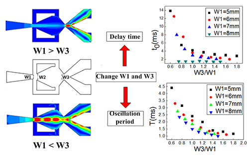
3.1. Effect of Power Nozzle Exit Width and Throat Width on the Delay Time
The delay time (t
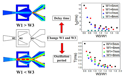
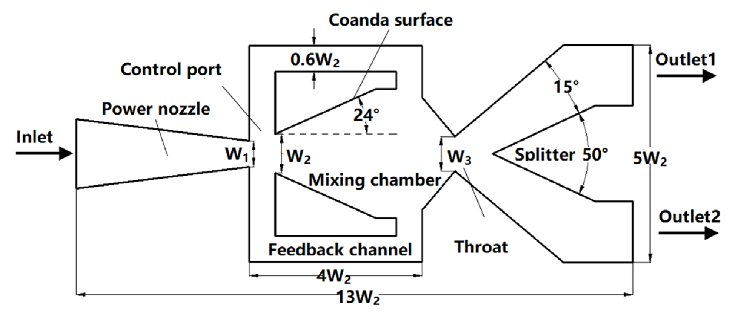
0) is a working parameter of the oscillator. It represents the period of time during which the working fluid flows into the oscillator until the fluid deflects in the mixing chamber. There is a throat in this oscillator. When W1 > W3, the throat was located at W3; the upstream flow of the throat is subsonic. Thus, the jet Mach number at the power nozzle exit is less than 1. The fluid in the mixing chamber is also subsonic. When W3 > W1, the throat was located at W1; the downstream flow of the throat is supersonic. The jet Mach number at the power nozzle exit is equal to 1. The fluid in the mixing chamber is also supersonic.
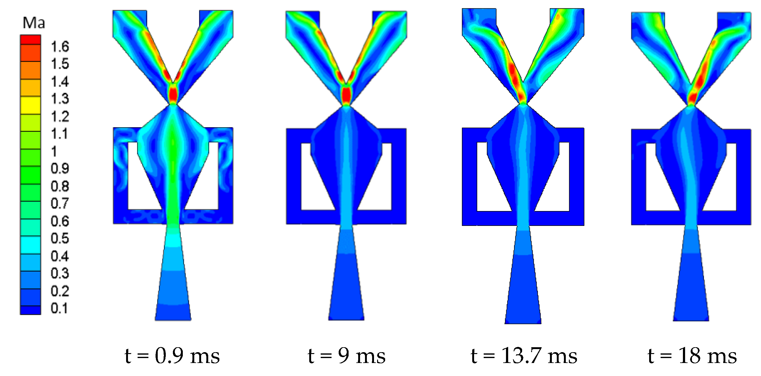
Figure 5 shows the Mach number distribution of model M
5, 3 at different times. At t = 0.9 ms, the main jet flows through the power nozzle into the mixing chamber. At this point, the whole flow field is centrosymmetric, and most of the fluid flows out from the throat. Under the action of the splitter, the main jet flows to the two outlets with an equal flow rate. A small portion of the fluid begins to flow into the feedback channel (which is not yet full). Because the narrowest area of the model is at the throat (width of 3 mm), the upstream jet of the throat is subsonic, and the maximum Mach number of the jet in the mixing chamber is 0.9. The jet downstream of the model accelerates to Mach 1.6. At t = 9 ms, the flow field is still centrosymmetric. The increase of pressure in the mixing chamber and the feedback channel causes the maximum value of the Mach number of the jet in the mixing chamber to decrease to 0.5. At t = 13.7 ms, the jet in the mixing chamber begins to oscillate. This means the delay time t
0 for this case is 13.7 ms. At t = 18 ms, the jet in the mixing chamber deflects to the left wall, and most of the jet flows through the throat to the right outlet.
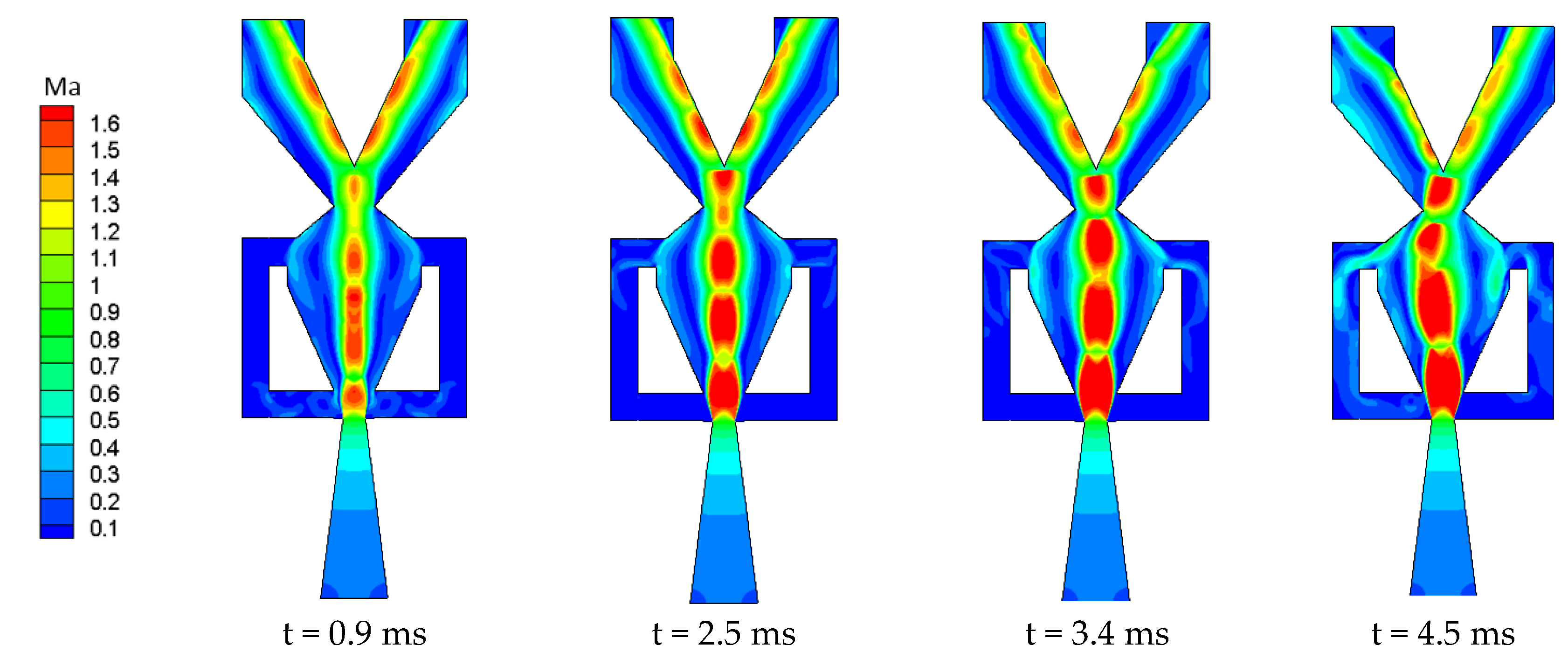
Figure 6 shows the Mach number distribution of model M
5, 9 at different times. The W
3 (9 mm) of the model is larger than the power nozzle exit width (5 mm) (in fact, W
1 is the throat in this case). At t = 0.9 ms, the fluid expands rapidly after flowing through the nozzle with the smallest flow cross-section, and the maximum Mach number in the mixing chamber is 1.5. The whole flow field is centrosymmetric. At t = 2.5 ms, the jet undergoes many expansion and compression processes. The Mach number in the mixing chamber is greater than 1.6, the width of the jet after the expansion is basically the same as the width of the inlet of the mixing chamber, and the jet is closer to the side walls. The jet is more prone to attach to the side walls under small disturbances, which may lead to a decrease in the delay time. At t = 3.4 ms, the jet begins to deflect and the flow field becomes asymmetrical; this occurs 10.3 ms earlier than in model M
5, 3. At t = 4.5 ms, the jet deflection amplitude increases and the flow enters the feedback channel.
When W1 = 6 and 7 mm, the development law describing the starting time of the oscillator is similar to that for W1 = 5 mm as W3 increases. By comparing the Mach number distributions of models M5, 3 and M5, 9, it can be seen that, when W3 < W1, the mixing chamber jet is in the subsonic state before the periodic oscillation, and the Mach number decreases with time. The width of the jet core also decreases. Supersonic jets are produced downstream of the throat. When W3 > W1, the jet in the mixing chamber is supersonic. The width of the main jet increases with any increase in W3, whereas the delay time t0 decreases as W3 increases.
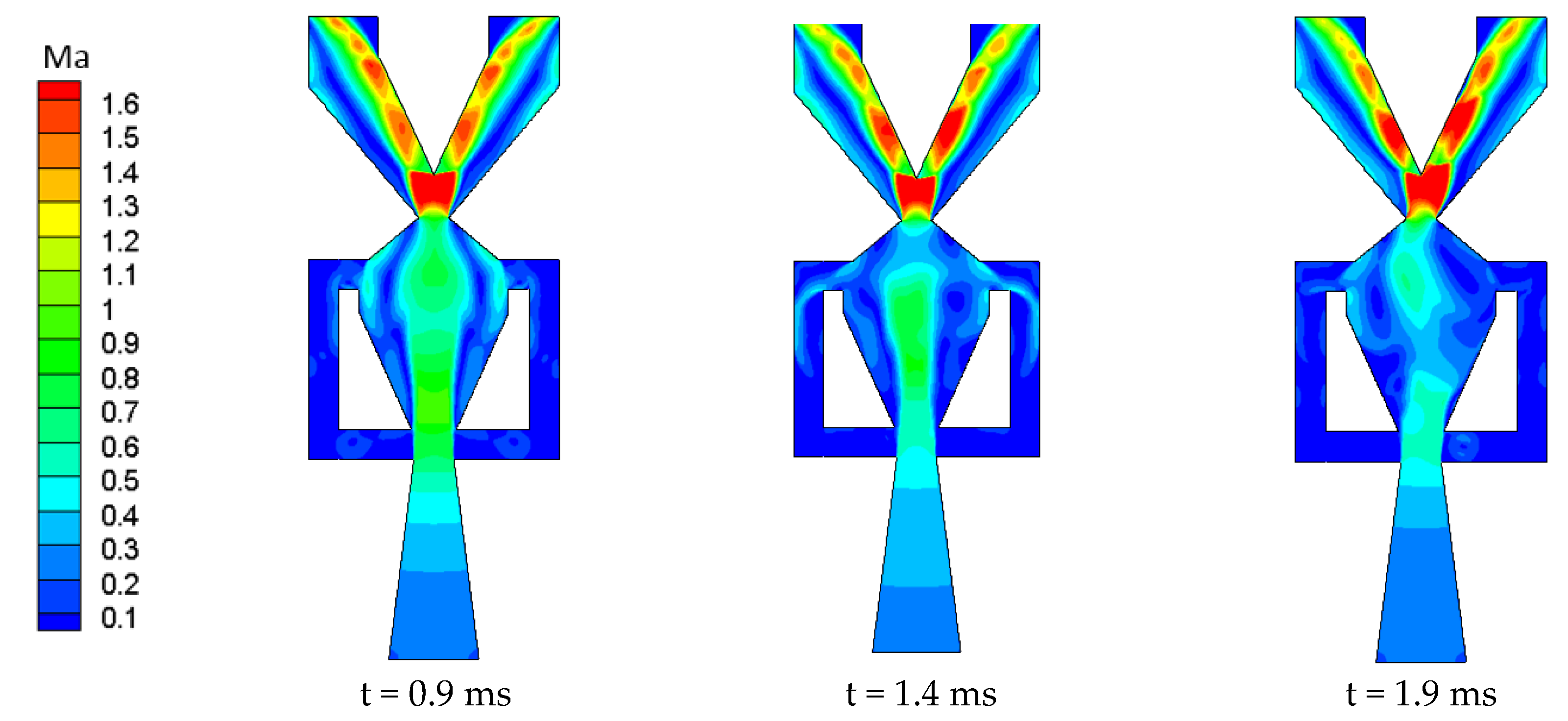
Figure 7 shows the Mach number distribution of model M
8, 6 (i.e., when W
1 is close to W
2) at different times. At t = 0.9 ms, the center of the flow field is symmetrical, and the width of the main jet is close to W
2. The main jet is very close to the side wall, meaning that the jet can easily become attached to the wall under a small disturbance. At t = 1.4 ms, the jet in the oscillator begins to deflect. At this point, the throat is the narrowest part of the oscillator, and the Mach number of the jet in the mixing chamber is less than 1. At t = 1.9 ms, the jet is attached to the right wall, the Mach number of the main jet in the mixing chamber has decreased, and the flow rate of the right outlet is beginning to increase.
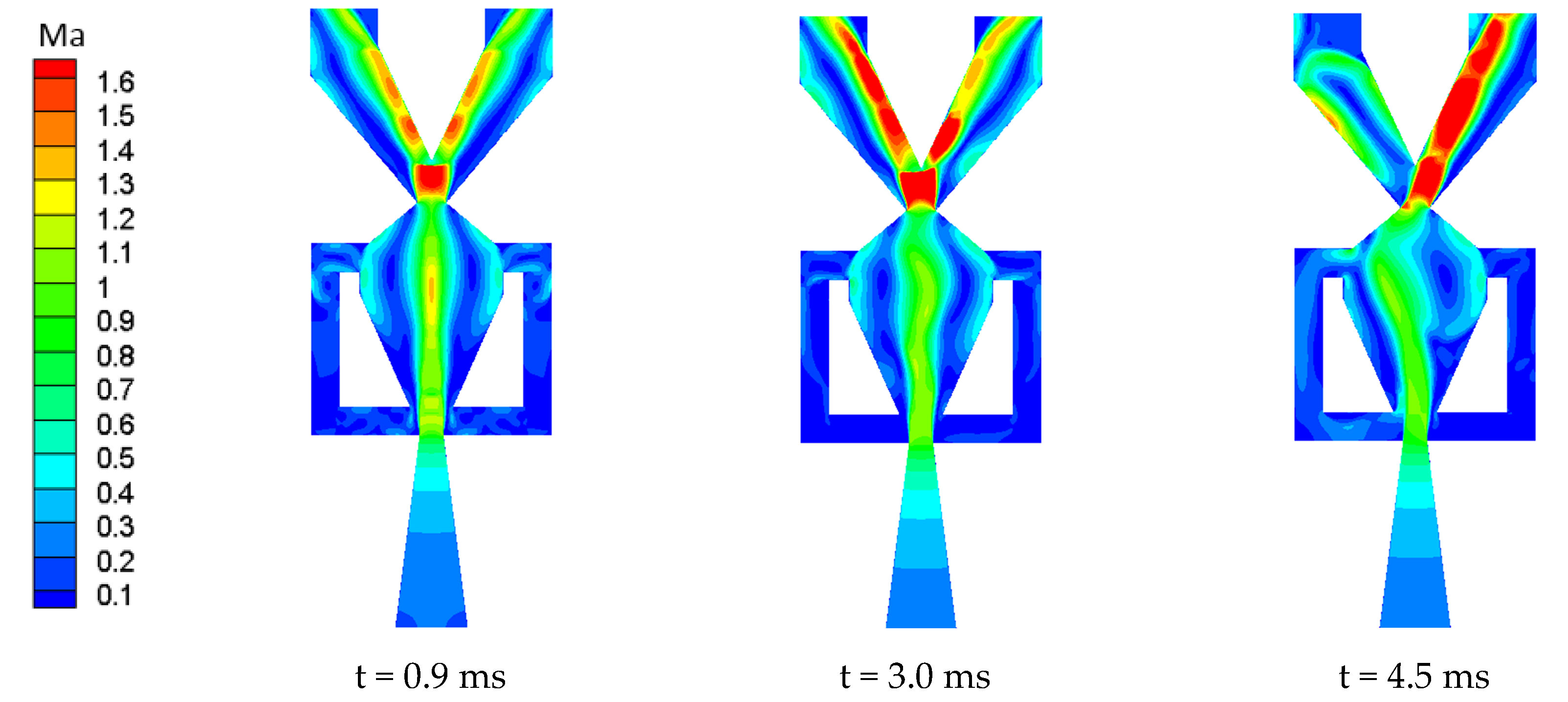
Figure 8 shows the Mach number distribution of model M
5, 6 at different times. At t = 0.9 ms, the center of the flow field is symmetrical, and the width of the main jet is close to W2. The jet width is smaller than that in
Figure 7, which makes it more difficult for the jet to attach to the mixing chamber wall. At t = 3.0 ms, the jet in the oscillator begins to deflect, which is delayed by 1.6 ms compared with model M
8, 6. At t = 4.5 ms, the jet is attached to the left wall, evidently.
Figure 9 shows the Mach number distribution of model M
8, 12 at different times. At t = 0.9 ms, alternating expansion and compression waves can be observed in the mixing cavity. Under the limitation of the inlet W
2 of the mixing cavity, part of the jet moves toward the control port of the feedback channel. A deflection of the main jet is observed at t = 1.2 ms, at which point the jet width is still larger than that at the inlet of the mixing chamber W
2. At t = 1.5 ms, the jet has obviously attached to the left wall of the mixing chamber.
Figure 7 and
Figure 9 illustrate the difference of flow characteristics while the fluid is subsonic and supersonic in the oscillating cavity, respectively.
The oscillator delay time t
0 is shown in
Figure 10. When W
3/W
1 > 1, there was subsonic jet in the mixing chamber. When W
3/W
1 > 1, there is a supersonic jet in the mixing chamber. For oscillators with W
1 = 5–7 mm, a change in W
3 produces a similar variation in the delay time, that is, as W
3 increases, t
0 gradually decreases, with the rate of decrease initially being fast before slowing down. This phenomenon is due to the change of fluid in the mixing chamber from subsonic to supersonic. For the jet oscillator with W
1 = 8 mm, increases in W
3 have little effect on the delay time t
0, which remains at approximately 1.4 ms. When W1 = 5 mm, with the increase of W3, the subsonic flow in the mixing chamber converts to supersonic flow because of the change of throat position. The value of W
3 where the flow speed in the mixing chamber changes from subsonic to supersonic is 5 mm. Therefore, the feedback flow has faster velocity to form the steady oscillation, which can be observed in
Figure 11.
3.2. Activation Mechanism of Oscillator
For all cases with fixed W1, W3 changed from 3 to 15. The numerical results show that the jet cannot oscillate after W3 increases above a certain value, which is regarded as the critical value. In this paper, the corresponding W
3 at which the jet is no longer oscillating is called the critical throat width, W
cr.
Table 1 presents the W
cr values corresponding to different W
1.
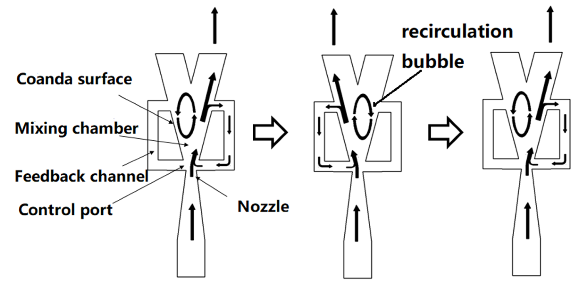
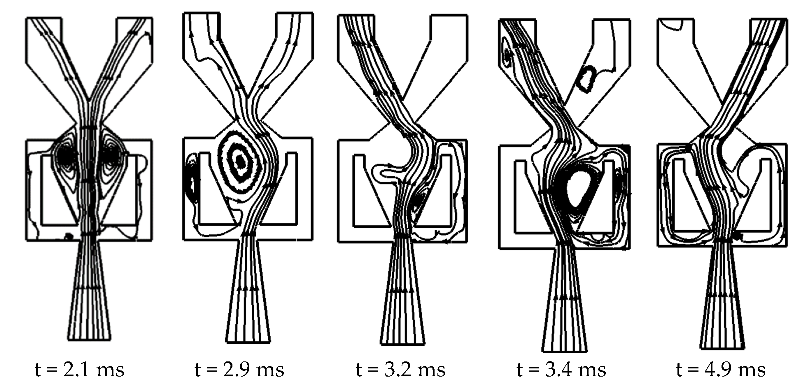
Figure 12 shows the streamline distribution of model M
7, 10 from the beginning of the jet to the time of the steady oscillation. At t = 2.1 ms, the main jet is centered in the mixing chamber. The two same recirculation bubbles arise. At t = 2.9 ms, the jet in the mixing chamber is obviously deflected to the right. At t = 3.2 ms, part of the fluid is flowing into the right feedback channel. At t = 3.4 ms, the jet in the mixing chamber is completely attached to the left wall, and a large recirculation bubble is produced between the jet and the right wall. The jet is “squeezed” onto the left wall, which is beneficial to the formation of the periodic oscillating jet. At t = 4.9 ms, the main jet has become fully attached to the left wall.
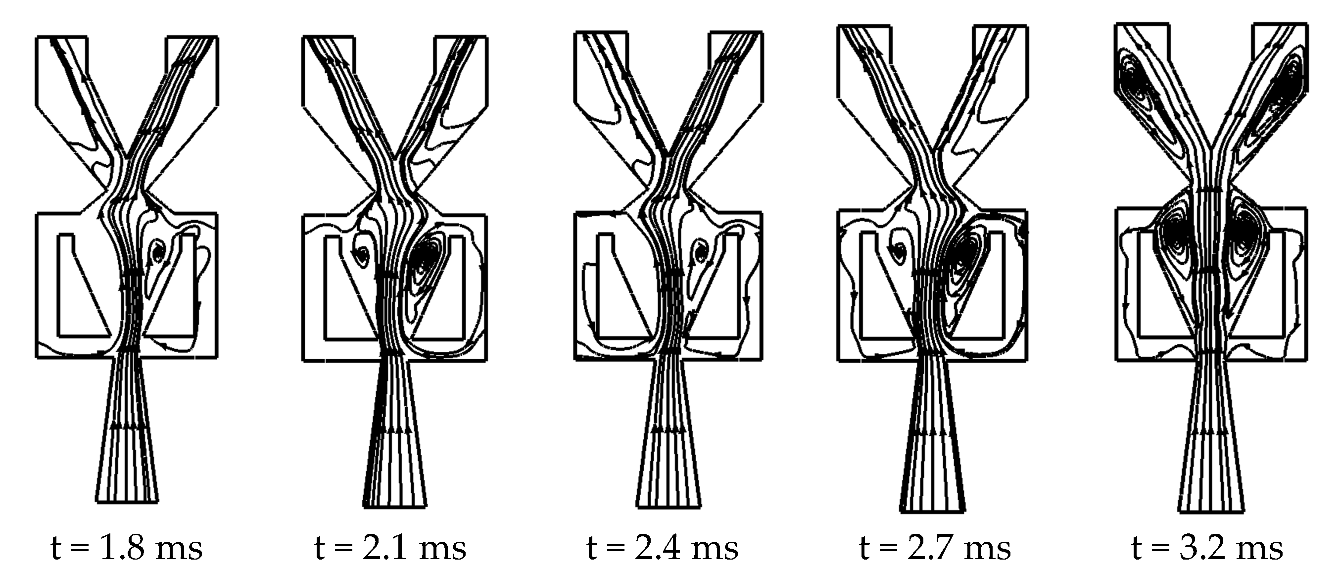
Figure 13 shows the streamline distribution of model M
7, 11 at different times. At t = 1.8 ms, the jet in the mixing chamber deflects to the left under the action of small disturbances. Compared with model M
7, 10, the increase in throat width W
3 intensifies the expansion of the jet in the mixing chamber, and the jet flow rate increases after expansion. More feedback flow is required to change the deflection direction, thus this increase in expansion is disadvantageous to the oscillation of the jet. At the same time, the rapid expansion causes the jet width to become greater than W
2, and a small part of the jet flows into the control ports on both sides. For the convenience of description, this small part of the fluid is called the “countercurrent”; this hinders the feedback flow acting on the main jet. At t = 2.1 ms, the jet in the mixing chamber slightly deflects to the right, the deflection angle increases slightly, and an increased countercurrent flows into the right control port. As W
3 increases, the jet flows out from the throat more easily. This means there is less fluid flowing into the feedback channel. Between t = 2.4 ms and t = 2.7 ms, the jet in the mixing chamber is deflected several times, and the angle of deflection gradually decreases. At t = 3.2 ms, the jet in the mixing chamber stops oscillating.
Figure 12 illustrate the oscillating process from the beginning of the jet deflection to the formation of steady oscillation.
Figure 13 show the reason the oscillator (M
7, 11) cannot work.
3.3. Effect of Power Nozzle Exit Width and Throat Width on the Oscillation Period
Sweeping time (t
c) is the fluid switching time from the one side wall of the mixing chamber to the other side wall. When the jet is completely attached to one side wall, it will stay on the wall for a short time until there is enough energy at the outlet of the feedback channel to deflect it to the other side. The stay time is the wave propagation time in the feedback channel (t
c). The oscillation frequency f can be expressed as:
The propagation velocity of the expansion and compression waves is equal to the speed of sound, thus tc is determined by the length of the feedback channel and the local sound velocity. If all the inlet gas parameters are fixed, the sound velocity and the feedback length of the different oscillators will be equal, thus the propagation time tc will remain unchanged. Hence, the oscillation period is determined by the sweeping time ts.
Figure 14 shows the oscillation periods of different oscillator models that produce stable oscillations. The oscillation period gradually decreases as the throat width W
3 increases, but the rate of decrease is becoming smaller. This phenomenon is due to the change of fluid in the mixing chamber from subsonic to supersonic. In addition, for a constant W
3, the oscillation period decreases as W
1 becomes smaller. Bigger width of the main jet not only decrease the delay time, but also increase the oscillation frequency. Because the main jet is more prone to attach to both side walls, the sweeping time is reduced.
Comparing
Figure 10 and
Figure 14, while t
0 becomes insensitive to W
1 as W
1 increases to greater than 8 mm, T is sensitive to W
1. The delay time (t
0) represents the period of time during which the working fluid flows into the oscillator until the fluid is attached to either side wall in the mixing chamber. The wider jet is more easily attached to the wall. Thus, the delay time is related to the jet width. When W
3 is fixed, with the increase of W
1, the jet width increases and the jet is more easily attached to the wall, thus the delay time is shorter. When W
1 increases to greater than 8 mm, the jet width is very close to the inlet width of the mixing chamber W
2, which makes the jet easy to attach to the wall under only small disturbance. Therefore, t0 becomes insensitive to W
1 as W
1 increases to greater than 8 mm. When the fluid forms a steady oscillation, the oscillation period T is mainly determined by the jet velocity. When W
3 is fixed, the jet velocity decreases as W
1 increases. Thus, T is sensitive to W
1. The jet velocity increased quickly then slowly as W
3/W
1 increases. For example, for models M
5,3, M
5,5, M
5,7, and M
5,9, the average velocities at W
1 are 100, 180, 246, and 262 m/s respectively. When W
3 increased from 3 to 5 mm, the velocity has increased 80 m/s. However, when W
3 increased from 7 to 9 mm, the velocity has increased only 16 m/s. When the W
1 is fixed, t
0 and T are mainly determined by the jet velocity. Thus, t
0 and T decline quickly at first and then slowly.
Figure 15 and
Figure 16 show the velocity and static pressure variations of the jet over one cycle of model M
6, 6, respectively. At t = 0, most of fluid flows out of the left outlets, as shown in
Figure 15a. Part of the fluid enters the right feedback channel, which causes the pressure rise inside the right channel, as shown in
Figure 15a and
Figure 16a. The feedback flows out of the right control port acting on the main jet, allowing the main jet to deflect to the left. At this time, a high-pressure zone (pressure > 2.8 atm) can be observed at the left wall, as shown in
Figure 16a, and this zone of high pressure moves downstream along the wall (the direction of motion is marked by the red arrow). At t = 0.25T, the jet has become completely attached to the left wall. The backflow region on the right side of the mixing chamber occupies half the area. The pressure in the right feedback channel decreases and that in the left feedback channel increases, as shown in
Figure 16b. The pressure signal is transmitted to the left control port through the left feedback channel. At t = 0.5T, the feedback flow acts on the main jet, which sweeps to the right, and the high-pressure region appears on the right side of the mixing chamber. The pressure and velocity distributions at this moment are exactly the opposite of those at t = 0. The main jet becomes completely attached to the right wall at 0.75 T, and the backflow region on the left side of the mixing chamber reaches its maximum size.


