1. Introduction
For photosynthesis, plants need light of varying intensity and spectral distribution depending on their growth stages. In recent years, the use of light-emitting diode (LED) grow lights in large-scale indoor farming is increasing exponentially due to their ability to stimulate plant growth by providing controlled amounts of light at various growth stages [
1,
2,
3,
4]. LEDs are solid-state devices that emit light, the wavelengths of which lie in narrow bands with high photon flux, which allows the manipulation of the spectral characteristics and intensity of the light. In general, LED chips convert about 50–70% of the input power into light, and the remaining power is dissipated as heat, depending on the operating junction temperature and efficiency. For instance, a typical industry standard LED grow light with 1 kW input power generates the equivalent of 1000–1500 W/m
heat flux on the LED circuit board depending on the design. Since operating LED grow lights at higher temperatures significantly reduces the efficiency and reliability of the LED chips, as well as causes chip failure, proper cooling of LED grow lights is a critical design requirement to maintain the high efficiency and reliability of the LED chips [
5,
6]. Therefore, the heat transfer must not cause the surface to exceed the maximum allowable temperature. This temperature has to be related to the LED junction temperature and may well change with time as LEDs generate more heat as they age, e.g., [
5,
6]. Thus, a reasonable level of conservatism is needed in heat sink design. In other words, the design for a new grow light should provide a maximum fin surface temperature somewhat below the allowable maximum.
Using computational fluid dynamics (CFD) and experiments, this paper develops a novel heat sink design for natural convection cooling of LED grow lights, which is found to significantly improve the heat transfer performance, as well as allow close control of the maximum surface temperature and can be implemented in cooling electronics whenever natural convection can be used. A limited CFD analysis was used by [
6] to study cooling of LEDs, but few details were given and no comparison made to measured fin temperatures. We are unaware of any further CFD studies for LEDs.
Currently, almost all LED grow lights are cooled using forced convection air cooling. Fans remove the heat locally either by forcing air through the heat sinks mounted on the LED circuit boards or directly forcing air through the circuit board surface. As the convected warm air heats up the air around the plants, the indoor warm air is removed again through a large-scale air-conditioning system to maintain suitable indoor air temperature and humidity for the plant. Because fans consume a significant amount of power, as well as being points of failure and cost, they may not be the best method for cooling LED grow lights. Further, if fans are used, the LED grow lights are highly susceptible to damage from moisture, water, and dust. Failure of fans can lead to damage of LED chips or the grow light. As an alternative, natural convection cooling employing finned surfaces or heat sinks does not require any moving parts, and there is lower susceptibility of damage due to moisture and water ingression. However, a major design challenge with conventional natural convection cooling is that it has a relatively low heat transfer rate compared to forced convection cooling, practically limiting the cooling performance and reliability of LED grow lights. It is worth noting that for conventional fins, high heat transfer is associated with high surface temperature, which may exceed the component tolerance. Therefore, novel heat sink designs that can increase natural convection heat transfer without exceeding the component maximum temperature are highly desirable. Considering the typical heat flux, i.e., heat transfer per unit base surface area
, of about 1000–1500 W/m
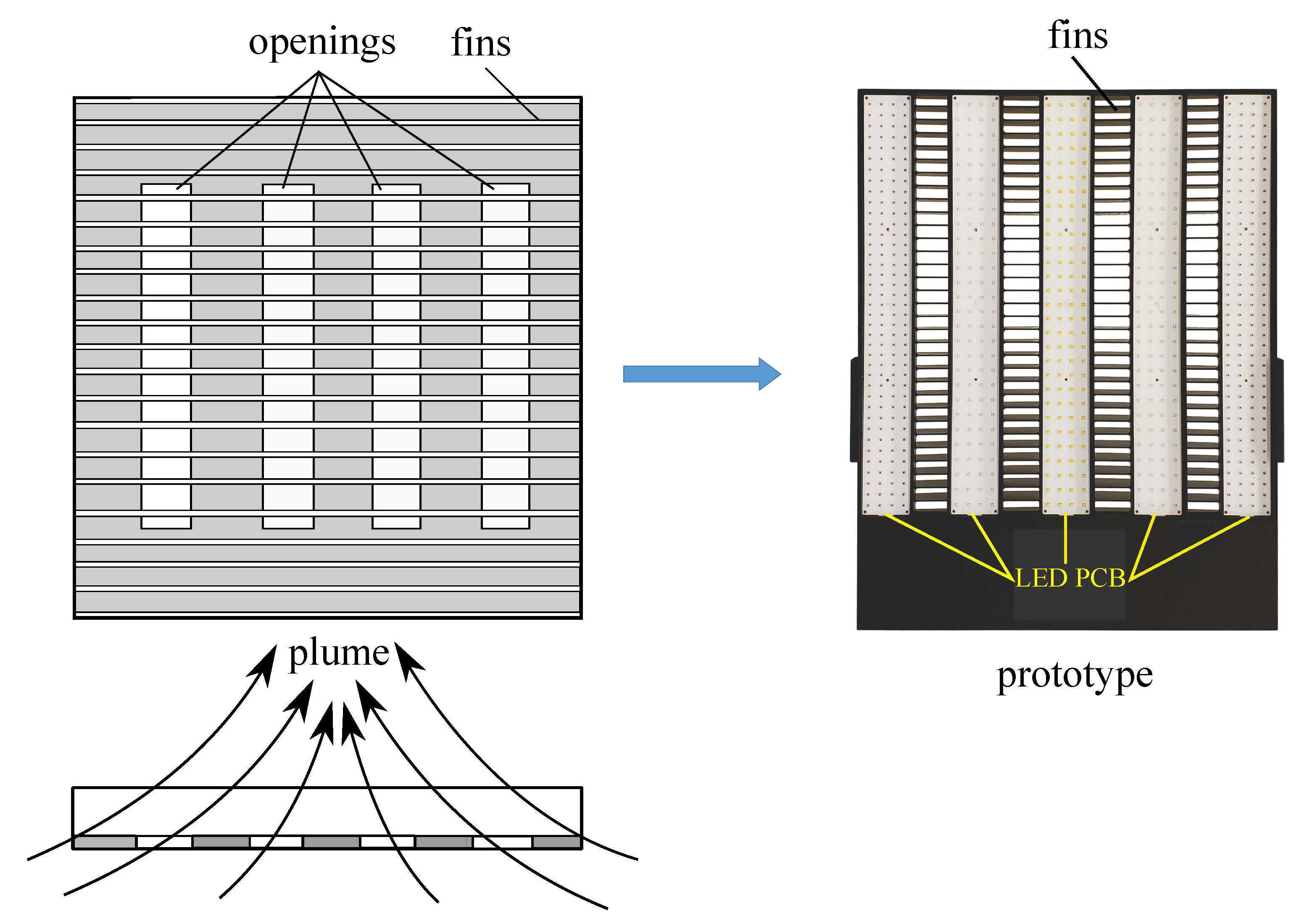
from the LED circuit board, efficient operating temperature limits of the LED chips, and currently available high-efficiency LED chips, a new heat sink design proposed here shows a promising cooling performance, as well as potential economic benefits for LED grow lights. The new heat sink is a rectangular array of straight fins with openings in the base as depicted in
Figure 1. While a number of fin designs can be used with this design concept, the most commonly used rectangular array of straight fins on a horizontal surface is considered in this work. The results of this study show that the new design increases the vertical flow of air and hence the heat transfer. For the particular design investigated here, it was found that such a design can transfer more than 1075 W/m
within an efficient operating temperature range of LED chips, which is about 53% greater than the rectangular fins without openings in the base.
Natural convection cooling occurs due to buoyancy forces as a result of differential heating of air around the fin surfaces, and the heat transfer occurs across the thermal boundary layer [
7,
8,
9]. A circulatory thermal flow field develops around the finned surfaces as a result of downward flow of cold air and upward flow of warm air. The upward and downward flow of air results in a vertical converging draft of air, commonly referred to as a “chimney” or “plume”, on which the natural convection heat transfer relies [
7,
10,
11,
12,
13]. As a consequence, the flow field exhibits a very complex three-dimensional fluid motion with heat transfer. Therefore, improved understanding of the flow and heat transfer characteristics around the finned surfaces is crucial to increase convection cooling. Incorrectly designed finned surfaces not only lead to lower heat transfer than the surfaces without fins, but also increase the footprint area and weight of the finned surfaces [
10,
11,
14,
15,
16,
17]. While a number of fin designs are available [
18,
19,
20,
21], the new heat sink design is based on the most commonly used rectangular array of straight fins on a horizontal surface, as depicted in
Figure 1, which can be easily integrated into the design of LED grow lights. There are numerous studies on natural convection cooling of these fins [
10,
11,
19,
22]. Earlier experimental work of Jones and Smith [
11] on rectangular fins on a horizontal surface showed that for the same height, length, and number of fins, the optimum fin spacing and array width transferred significantly more heat flux
than very narrow and wide fin arrays. This revealed that the width of the fin array or the fin spacing is an important parameter to maximize
. The physical basis is that the flow of cooling air from the array sides, i.e., in the transverse direction or width-wise, is as important as the flow in the longitudinal direction from the channel ends. As the highest
Q is associated with the highest surface temperature [
23], maximum temperature
is to be constrained, so alternative flow mechanisms are needed to achieve high
Q. The design implication is that wider fin arrays should have openings in the base to increase downward flow of cooling air or from the array sides to maximize
. This is due to the fact that in wider arrays, air flow from the array sides cannot reach the array center for cooling. To address this problem, a new heat sink based on rectangular straight fins with openings in the base was designed, which significantly increased vertical flow of cooling air around the fins and heat transfer. A related study was done by [
24] on the heat sink with perforations in the fin base. They showed that perforations increased the heat transfer and air flow. As the heat flux in LED grow lights is significant, large openings are needed. Furthermore, due to the design requirements of LED grow lights, rectangular openings are suitable. The literature review revealed that there are no prior studies on the design of natural convection heat transfer from rectangular straight fins with large rectangular openings in the base, i.e., between the LED circuit boards, with specific applications to natural convection cooling of LED grow lights.
The paper is structured as follows. In the next section, the new heat sink design for natural convection cooling of LED grow lights is presented.
Section 3 describes the numerical method used in the conjugate heat transfer simulations.
Section 4 presents the results of heat transfer from optimum rectangular fins without openings and new heat sink design with openings in the base. Experimental results of the thermal performance of a prototype LED grow light with the new heat sink are presented. Finally,
Section 5 summarizes the main conclusions.
3. Computational Model and Validation
We analyzed the conjugate heat transfer and flow characteristics using three-dimensional, steady state, laminar flow simulations with variable air properties. The simulations were conducted on the commercial computational fluid dynamics (CFD) code ANSYS Icepak-Fluent [
26]. The governing equations are the conservation of mass, momentum, and energy for the flow and the heat conduction equation for the solid, which are written in Cartesian co-ordinates, with
x in the direction of the fins,
y the vertical, and
z in the transverse direction normal to the fins. The following equations are solved:
Continuity equation for the steady flow:
Energy equation:
where
S is the source term for radiation. The temperature distribution within the fins was computed by the steady state Laplacian with constant thermal diffusivity. In natural convection problems in fins, Rayleigh numbers
< 10
indicate a laminar flow, with transition to turbulence occurring over the range of 10
<
< 10
[
26].
is defined as
, where
is the air density,
is the thermal expansion coefficient,
is the fin surface temperature,
is the ambient temperature,
L is the characteristic length of the fins,
is the kinematic viscosity of air, and
is the thermal diffusivity. As
9.46 × 10
in the fins examined in this work, laminar flow was assumed. Radiative heat transfer was considered using the surface-to-surface radiation model [
26,
27,
28]. For brevity, we do not show the model equations, which can be found in the references [
26,
28]. To account for the variation of air properties, such as density, viscosity, thermal conductivity, and diffusivity due to temperature changes, the ideal gas law was used with experimental data for the property variations. Viscosity
was computed using Sutherland’s law [
13] as:
where
T is expressed in degrees Kelvin and
in kg/ms. Similarly, density is calculated from the ideal gas law as:
where
R is the universal gas constant and
is the operating atmospheric pressure. The variations of air properties with temperature used in the simulations are presented in
Figure 2 of [
23]. The computational domain was discretized with fully structured hexahedral grids with high resolution in the near wall region to capture the effects of the thermal boundary layer more accurately; see
Figure 2. Opening type of boundary conditions were used at all sides of the computational domain with the buoyancy enabled, and ambient temperature and pressure were specified. The details of the numerical scheme and grid independence study are similar to the one reported in the reference [
23] and are omitted here.
The computational model was validated against the measured heat transfer from rectangular fins on a horizontal surface without openings by Jones and Smith [
11], which is possibly the most systematic experimental study available in the literature. The details of geometrical parameters and experimental results are available for different fin configurations, which allowed us to make comparisons between the CFD and experimental results and investigate the optimum fins for the new heat sink design. The details of the fin geometrical parameters and temperature variations in the experimental measurements used in the CFD simulations are summarized in
Table 1. All the fin configurations tested by Jones and Smith [
11] have length
L = 254 mm, fin thickness
t = 3.17 mm, and number of fins
n = 7. Only fin height
H and spacing
s were varied, and thus, the width of the fin array,
W, was different for each
s. In the measurements of Jones and Smith [
11], average surface temperature and ambient temperature were considered to calculate the temperature difference. The temperature difference in the CFD calculations was based on the difference between the maximum temperature on the fin surface and the ambient temperature. To quantify the thermal performance of a particular fin design,
was used as in Jones and Smith [
11]. The comparison of the CFD and the experimental results for
is shown in Figure 8 of [
23]. A maximum relative error of about 11.34% was found between the experimental and CFD results, which is a fairly good agreement in view of the uncertainties incurred in both the experimental measurements and the numerical simulations. Jones and Smith’s experimental results had about ±10% uncertainty. Importantly, the computed
has its maximum at the same
s as the measurements, despite the difference in magnitude. The fundamental heat transfer characteristics and flow features relevant to the proposed heat sink design are briefly investigated in the next section.
5. Conclusions
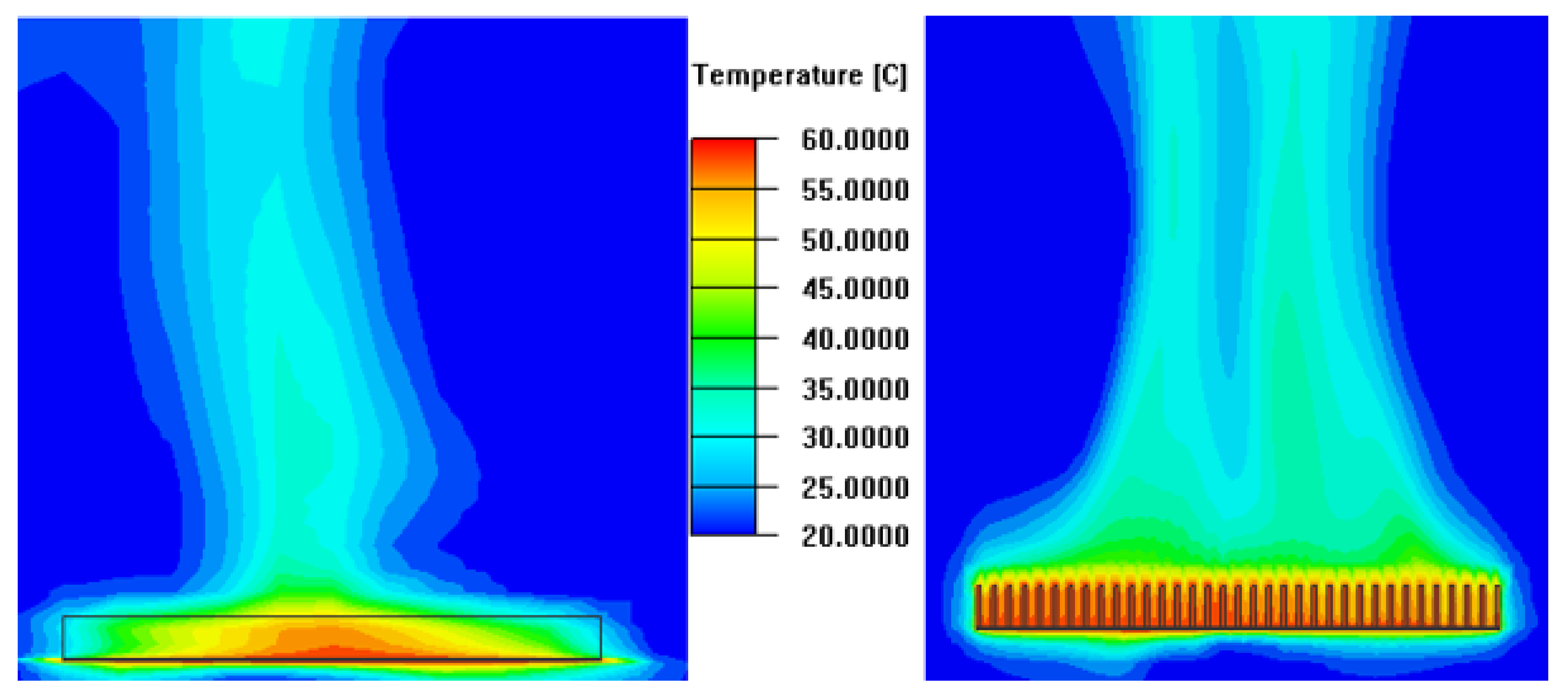
A novel heat sink design based on rectangular straight fins with openings in the base for natural convection cooling of LED grow lights is presented. Significant improvement in natural convection heat transfer was found by incorporating openings in the base of a rectangular array of straight fins. The heat sink can be mounted on top of the LED circuit board as an enclosure for natural convection cooling of the circuit board. Three-dimensional, steady state laminar flow, conjugate heat transfer simulations, and experiments were conducted on a prototype LED grow light to assess the thermal performance of the new heat sink. The results of conjugate heat transfer simulations of a rectangular fin array without openings in wider fin arrays showed that the air flow from the array sides toward the center decreased considerably, resulting in a significant decrease in heat transfer. To improve air flow around the fins and the array center, openings were made in the base of the same fin array, which considerably improved the vertical air flow and heat transfer. Based on these findings, a prototype LED grow light with the new heat sink design was fabricated and experimentally tested for thermal performance.
Measurements of the base temperature of a prototype LED grow light agreed with the simulations to within a relative error of 4.53%. The measured temperatures were about C lower than the assumed allowable maximum temperature of the base of the heat sink, which introduces a desirable conservatism in the design. This was needed as the base temperature may differ from the LED junction temperature and LED grow lights produce more heat as they age. Further, the need for conservatism suggests that an aggressively optimized design of the heat sink for a new grow light may become ineffective with time. The experimental results showed that openings significantly increased natural convection heat transfer. For a typical industry standard size of LED grow light investigated here, it is shown that more than 1075 W/m heat transfer can be achieved with natural convection cooling within an efficient operating temperature range of LED chips. Therefore, the new heat sink design can be used for natural convection cooling of LED grow lights that are expected to be the main technology of the next-generation horticulture industry. Further, the new design can be easily incorporated in many microelectronics and light enclosures, where natural convection cooling can be used. Finally, it is worth pointing out that further research is recommended to investigate the influence of openings on heat transfer, and generalized design correlations would be particularly useful for practical design applications.


