Article

Woven Fabric Triboelectric Nanogenerator for Biomotion Energy Harvesting and as Self-Powered Gait-Recognizing Socks

1
Key Laboratory of Textile Science & Technology, Ministry of Education, College of Textiles, Donghua University, Shanghai 201620, China
2
Key Laboratory of Advanced Technologies of Materials (Ministry of Education), School of Materials Science and Engineering, Southwest Jiaotong University, Chengdu 610031, China
3
Tsinghua-Berkeley Shenzhen Institute, Tsinghua Shenzhen International Graduate School, Tsinghua University, Shenzhen 518055, China
4
Violet Home Textile Science and Technology Company Limited, Nantong 226311, China
*
Authors to whom correspondence should be addressed.
Energies 2020, 13(16), 4119; https://doi.org/10.3390/en13164119
Submission received: 11 July 2020 / Revised: 31 July 2020 / Accepted: 2 August 2020 / Published: 10 August 2020
(This article belongs to the Section A: Sustainable Energy)

Abstract

:
In recent years, rapid advancements have developed in multifunctional and wearable electronics, which call for more lightweight, flexible energy sources. However, traditional disposable batteries and rechargeable batteries are not very suitable because of their bulky appearance, limited capacity, low flexibility, and environmental pollution problem. Here, by applying a mature manufacturing technology that has existed in the textile field for a long time, a woven fabric triboelectric nanogenerator (WF-TENG) with a thinner structure that can be mass-fabricated with low cost, perfect stability, and high flexibility is designed and reported. Due to the good intrinsic quality of TENGs, the maximum voltage of this WF-TENG can easily reach 250 V under a pressure of 3.5 kPa and a tapping frequency of 0.33 Hz. Because of the stable plain-woven structure, the output voltage can remain relatively stable even after the WF-TENG has been working for about 5 h continuously, clearly demonstrating its robustness and practical value. Moreover, good sensitivity endows this WF-TENG with the capability of being applied as self-powered sensors, such as a self-powered smart real-time gait-recognizing sock. This WF-TENG shows us a simple and effective method to fabricate a wearable textile product with functional ability, which is very meaningful for future research.

1. Introduction

The triboelectric nanogenerator (TENG) [1] is a promising energy-harvesting technology that can be a perfect alternative for the energy crisis and meets the energy demands for the sustainable development of society [2,3,4,5]. It can convert mechanical energy into electric power based on contact-electrification and electrostatic induction [6,7,8,9]. Due to its high efficiency in energy conversion, the TENG has been applied in vast fields to harvest energy, ranging from water [10,11,12], vibration [13,14], wind [15,16], oceans [17,18,19,20], and ubiquitous human motion [21,22,23], which is one of the most dispersed energies in the world. The output can not only be an energy source but also provide signals for self-powered functional sensors, such as the smart textile TENG, which has received intensive attention in recent years [24,25,26,27,28]. A self-powered smart textile TENG can be used to monitor human motion, personal health care [29], and medical care, which shows great application prospects in the future. The integration of TENGs with traditional textiles has also greatly advanced [30]. This combination endows the textile TENG with excellent electrical output properties and outstanding textile-related performance. Unlike common wearable electronics, the textile TENG can be directly used in our daily life with perfect performance and is lightweight, with washing durability, breathability, flexibility, and potential as a sustained, power-supplying source. In other words, it can be regarded as a part of the wearer’s body that monitors movement and health care without changing it or affecting normal life and comfortable sensations. However, most previous fabric-based TENGs have been fabricated in a complicated way with a time-consuming and tedious process [31,32]. In addition, the fibers or yarns that are used to fabricate the fabric-based TENG are somewhat expensive and hard to obtain [33,34].
Here, we report a woven fabric TENG (WF-TENG) for biomotion energy harvesting and as a self-powered and real-time gait recognition sensor. The plain structure is easily manufactured by a mature and efficient woven technology. In addition, the yarns directly used to fabricate the WF-TENG are commercial polyester (PET) yarn (RMB 2.78 yuan for 1000 m) and commercial wire (iron wire, RMB 23.2 yuan for 1000 m), which are very easy to obtain and cheap. The interwoven structure of the fabric endows the TENG with good stability and a smooth surface. The WF-TENG with dimensions of 10 × 10 cm2 can easily generate an open-circuit voltage of 200 V. Due to the intrinsic property of textile materials and the plain structure of the fabric, this WF-TENG is breathable, low-cost, flexible, and long-lasting. The long-term stability and durability of the WF-TENG were also investigated by allowing it to continuously work for about 5 h. In order to investigate the effect of different materials on the electrical output performances, the results of the WF-TENG pressed by different materials were compared and analyzed. Furthermore, with good sensitivity and fast response time to a variety of mechanical stimuli, self-powered real-time smart gait-recognizing socks are introduced and demonstrated in this paper. This research presents a WF-TENG that provides guidance on wearable electronics and takes a solid step toward the applications of textile-based TENG technology.

2. Materials and Methods

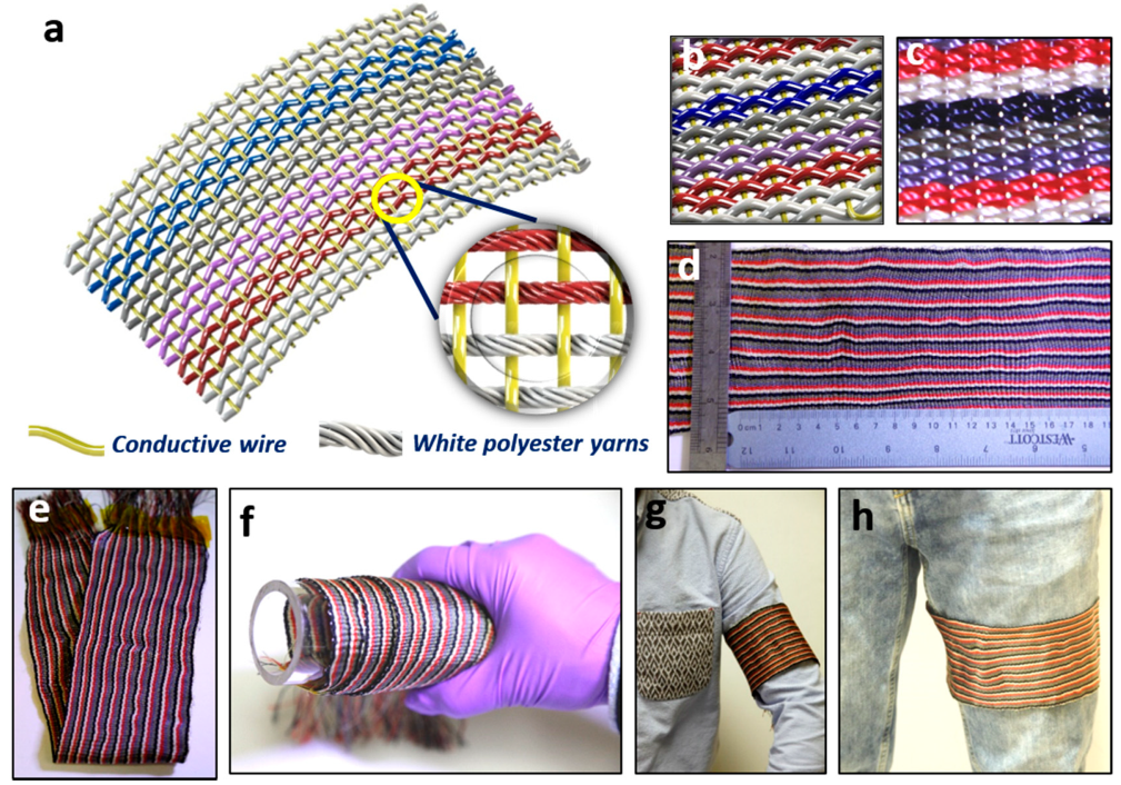
2.1. Structure and Design

The structure schematic illustration of the WF-TENG is presented in Figure 1a. The plain structure was chosen as the woven structure for its good stability and abrasion resistance, which indicates a stable electrical output performance. A soft iron conductive wire was chosen as weft yarn, which had a small diameter (0.25 mm) and high electrical conductivity (0.5 Ω cm−1) and was the electrode of the WF-TENG. Colorful PET yarns were chosen as warp yarns, and the yarn count of all colors was 210D (Daniel). PET not only is a very commonly used and cheap insulating textile material in the world but also has a high production output and good performance properties, such as high breaking strength. Furthermore, colorful PET yarns (white, red, purple, gray, and blue) make the fabric style of this wearable WE-TENG able to satisfy certain aesthetic requirements of the public. The detailed structure of the WF-TENG is shown in the enlarged view in Figure 1a. The structure schematic illustration and photograph of a real WF-TENG are shown in Figure 1b,c. Figure 1d shows a large-scaled WF-TENG that has been easily fabricated by a hand sample weaving machine, which indicates that this cost-effective WF-TENG can be mass-manufactured simply and highly efficiently by applying a mature weaving manufacturing technique that has existed for a long time. Due to the intrinsic performances of its textile material, this WF-TENG has good flexibility. As shown in Figure 1e,f, the WF-TENG can be bent, folded, and rotated around a tube. It can also be worn on the arm and thigh. Therefore, it is suitable for use for any flexible wearable electronics.

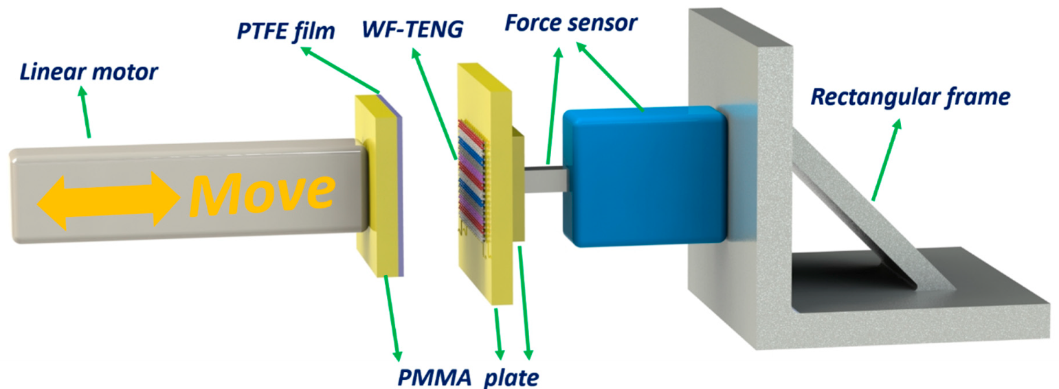
2.2. Test Method and Mechanism

As shown in Figure 2, a compressing operation between the WF-TENG and polytetrafluoroethylene (PTFE) film was implemented by a linear motor (LinMot E1100) that could mimic human motion and offered periodic contact-separation movements. One polymethyl methacrylate (PMMA) plate was fixed on a force sensor (Vernier LabQuest Mini), which was used to measure the pressure between the WF-TENG and PTFE film. This force sensor was fixed on a rectangular frame. An electrometer (Keithley 6514 System) connected to a computer and the WF-TENG was applied to test the open-circuit voltage (VOC), short-circuit transferred charges (QSC), and short-circuit current (ISC).
The compacted structure of the fabric endows the WF-TENG with good properties for generating electricity by contacting and separating from other dielectric materials, such as polyamide (PA) and PTFE. The electrical output performances were tested by using a linear motor to provide periodic contact-separation movements, as shown in Figure 2. There are generally four kinds of working modes for a TENG, including single-electrode mode, sliding mode, contact-separation mode, and freestanding mode. In this work, single-electrode mode is adopted, and the working mechanism is presented in Figure 3.
For better understanding this device, we chose the cross-section of the WF-TENG to analyze the working mechanism. Here, PTFE film was chosen as the dielectric layer for the contact-separation movement with the TENG. In the initial stage, no electrical potential exists between the surface of the PET yarns and the PTFE film. By pressing PTFE film onto the fabric, the surfaces of the PET yarns and PTFE film are charged with the same amount of opposite electric charges (Figure 3a). The PTFE film proves to be negatively charged due to the PTFE film’s ability to attract more electrons than the PET yarns. Once they are separating from each other, negative charges are induced in the electrode (conductive wire) by the positive charges on the PET yarns, generating an instantaneous electrical current from the conductive wire through the external loading to the ground (Figure 3b), due to the electrostatic induction effect. As the PTFE film is moving quite far away, a new electrical equilibrium is obtained, and the electrons stop moving (Figure 3c). As the PTFE film approaches the WF-TENG again, electrons flow inversely from the electrode (conductive wire) to the ground to achieve a charge balance (Figure 3d). When the PTFE film fully contacts the PET yarns, charge neutralization occurs again. Continuous contact-separation movements between the PTFE film and the PET yarns generate continuous alternating current outputs from the WF-TENG through the external loading.

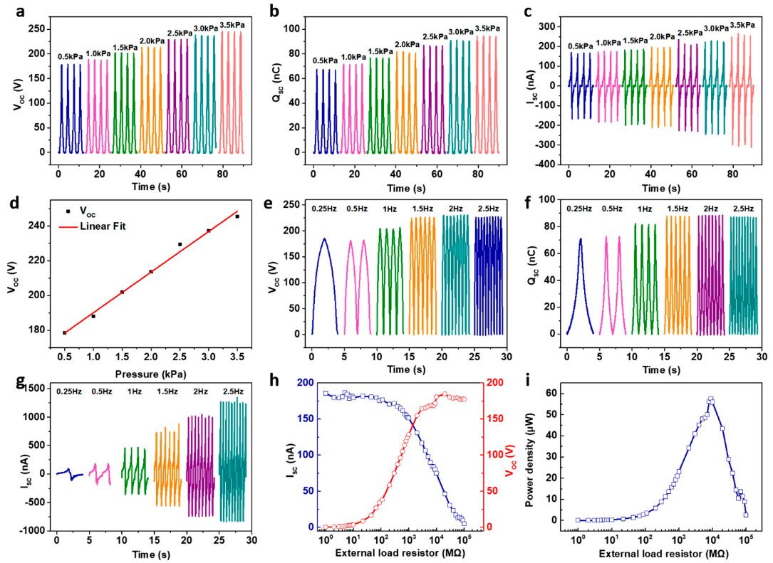
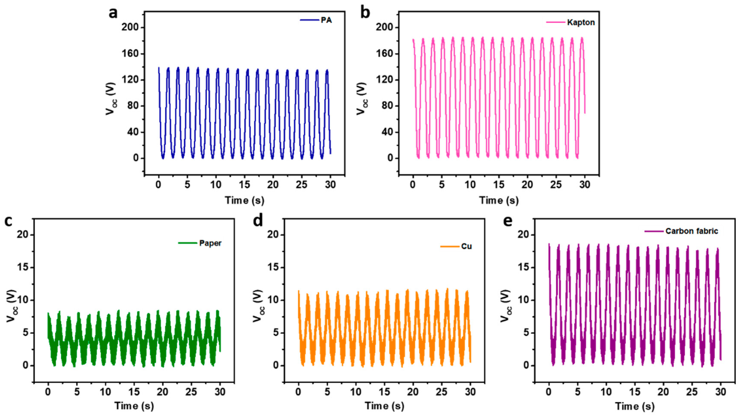
3. Results and Discussion

In order to characterize the electrical output performances of this WF-TENG, the linear motor was used in this work for the test in Figure 2. Figure 4a–c exhibits the test results of Voc, Isc, and Qsc under various pressures (ranging from 0.5 kPa to 3.5 kPa) with the same frequency (0.33 Hz). The contact area between the fabric TENG and the PTFE film is 10 × 10 cm2. With the pressure increasing, an obvious output increasing tendency can be observed in Voc (increasing from 175 V to 250 V), Isc (increasing from 170 nA to 320 nA), and Qsc (increasing from 65 nC to 95 nC). This is because the contact area between PET yarns and PTFE film increases when the pressure increases. As shown in Figure 4d, the VOC and pressure have a good linear relationship (the coefficient of determination R2 is about 0.990), which indicates that this WF-TENG can be used as a self-powered sensor. The electrical output performances of this woven fabric TENG tested under different frequencies and the same test pressure (3.5 kPa) are also presented in Figure 4e–g. The VOC and QSC nearly keep constant at 200 V and 80 nC, respectively, when the frequency increases from 0.25 Hz to 2.5 Hz. Nevertheless, the ISC increases from 96 nA to 1275 nA when the frequency increases. So, when this WF-TENG is used to harvest human motion energy, higher output performance can be obtained by increasing the contact frequency.
At a constant contact frequency (1 Hz), pressure (3.5 kPa), and area (10 × 10 cm2), the power density of the WF-TENG was investigated by connecting it in series with external variable resistors. Figure 4h shows that the output voltage increases significantly with the increment of resistance from 1 MΩ to 1000 MΩ and is then saturated when the load resistance further increases to 3000 MΩ. In contrast to the output voltage, the generated current illustrates a reversed tendency, as shown in Figure 4h. The peak power density P of the WF-TENG reaches 57.6 μW (or 5.76 mW/m2) under a load resistance of 9000 MΩ (Figure 4i), as calculated by P = UI, where U is the output voltage across the external load R, and I is the short-circuit current across R. Therefore, in the periodic contact-separation movements offered by humans, this WF-TENG can be used to harvest human biomotion energy.
In order to investigate the influences of different materials contacting the fabric on the electrical output performances of the WF-TENG, five other kinds of materials were chosen apart from PTFE film. They were PA film, Kapton film, paper, Cu film, and carbon fabric. These materials were tested under the same conditions. The output results are presented in Figure 5. Obviously, when contacting Kapton, the WF-TENG has the highest output voltage (184 V), which demonstrates the influence of contacting materials on the output performances of the fabric TENG. So, we can change the contact materials to get different output voltage to satisfy various applications.
According to the mechanism in Figure 3 and output data in Figure 5, the output of the WF-TENG is alternating current. Some electronic products, such as LEDs, can be directly powered by a WF-TENG, but most electronic products or energy storage equipment can only be powered by direct current. So, it was necessary to investigate the influence of a rectifier on the output performance of the WF-TENG. As shown in Figure 6a, the direct output Voc of the WF-TENG is about 220 V before rectification. When a rectifier is added into the circuit (Figure 6b), the output Voc drops to 190 V (Figure 6c). This indicates that the voltage drop should be taken into account when WF-TENG is used to offer direct current by a rectifier.
Due to the good stability of the fabric’s interwoven structure, the output stability of the TENG was also investigated in this work, as shown in Figure 7. PTFE film was chosen for the contact-separation movements with the WF-TENG. The test frequency and pressure were 0.6Hz and 3.5 kPa. As shown in Figure 7b, the output voltage of the WF-TENG is about 207 V at the very beginning, and the output voltage is about 152 V when the test is finished (Figure 7c). So, the output voltage can remain relatively stable even after the WF-TENG has been working for about 5 h continuously, clearly demonstrating its robustness and practical value. Therefore, this WF-TENG is suitable to be used as smart wearable electronics during an individual’s normal life with high output performances for energy harvesting.
As a practical application of this WF-TENG as wearable electronics in daily life, it can be fabricated as a self-powered gait-recognizing sock. In this work, the WF-TENG was attached under the socks by sticky tape, but in practice, it can be fabricated with socks as a whole or sewn under the sock. Figure 8a,b shows the photographs of the actual self-charging smart sock with two gaits, where the WF-TWNG has nearly the same size as the foot. In order to investigate the ability of the WF-TENG in human gait sensing, PTFE film was placed in a shoe as an insole. A tester wore the self-charging smart sock and the shoe. When the tester moved with different gaits, the output VOC was obtained by connecting the self-charging smart sock to the programmable electrometer (Keithley 6514) by an electrical wire. As shown in Figure 8c, the output voltages of various gait conditions are different. Kicking has the highest output voltage, and walking has the lowest output. According to these test results, the smart sock can distinguish the human gait according to the output voltage. This is because the pressure between the sock and the insole will vary with the gait. In other words, this self-powered smart sock can be used as a gait sensor to monitor the state of motion of people. In addition, this fabric TENG can also be applied in other places, such as the underarm. The demonstration and data show that the WF-TENG has wonderful potential applications as a sustainable and eco-friendly power source for wearable devices and self-powered smart sensors.

4. Conclusions

In conclusion, a fabric triboelectric nanogenerator based on single-electrode mode with a stable interwoven structure was designed and fabricated. Firstly, by being woven with colorful PET yarns, the wearable WF-TENG can be fabricated to satisfy certain aesthetic requirements of the public. Secondly, the WF-TENG can be used as a pressure sensor and harvest environmental and sustainable energy from human motion. The peak power density and open-circuit voltage are 5.76 mW/m2 and 250 V when the test area is 10 × 10 cm2. Thirdly, due to the stability of the woven structure, the output voltage of WF-TENG can remain relatively stable even after working for about 5 h continuously, clearly demonstrating its robustness and practical value. Furthermore, the flexible, lightweight, durable, and cost-effective WF-TENG can be fabricated into a pair of self-powered smart real-time gait-recognizing socks, which can be used to monitor the state of motion of people for health care or training purposes. This research presents a functional WF-TENG that provides guidance on wearable electronics and takes a solid step toward applications of textile-based TENG technology.

Author Contributions

C.C., L.Z., and W.D. conceived and performed the experiments; C.C., L.Z., L.C., and J.L. analyzed the data and wrote the paper; Z.D. and W.Y. supervised the experiments. All authors have read and agreed to the published version of the manuscript.

Funding

The authors are grateful for the support received by Graduate Student Innovation Fund of Donghua University (CUSF-DH-D-2019031).

Conflicts of Interest

The authors declare no conflicts of interest with this publication.

References

  1. Fan, F.-R.; Tian, Z.-Q.; Wang, Z.L. Flexible triboelectric generator! Nano Energy 2012, 1, 328–334. [Google Scholar] [CrossRef]
  2. Kwak, S.S.; Yoon, H.J.; Kim, S.W. Textile-based triboelectric nanogenerators for self-powered wearable electronics. Adv. Funct. Mater. 2019, 29, 1804533. [Google Scholar] [CrossRef]
  3. Wang, Z.L.; Chen, J.; Lin, L. Progress in triboelectric nanogenerators as a new energy technology and self-powered sensors. Energy Environ. Sci. 2015, 8, 2250–2282. [Google Scholar] [CrossRef]
  4. Wang, Z.L. Triboelectric Nanogenerators as New Energy Technology for Self-Powered Systems and as Active Mechanical and Chemical Sensors. ACS Nano 2013, 7, 9533–9557. [Google Scholar] [CrossRef] [PubMed]
  5. Ha, M.; Park, J.; Lee, Y.; Ko, H. Triboelectric Generators and Sensors for Self-Powered Wearable Electronics. ACS Nano 2015, 9, 3421–3427. [Google Scholar] [CrossRef] [PubMed]
  6. Xu, C.; Zi, Y.; Wang, A.C.; Zou, H.; Dai, Y.; He, X.; Wang, P.; Wang, Y.C.; Feng, P.; Li, D. On the electron-transfer mechanism in the contact-electrification effect. Adv. Mater. 2018, 30, 1706790. [Google Scholar] [CrossRef] [PubMed]
  7. Wang, S.; Lin, L.; Wang, Z.L. Nanoscale triboelectric-effect-enabled energy conversion for sustainably powering portable electronics. Nano Lett. 2012, 12, 6339–6346. [Google Scholar] [CrossRef] [PubMed] [Green Version]
  8. Wang, Z.L.; Wang, A.C. On the origin of contact-electrification. Mater. Today 2019, 30, 34–51. [Google Scholar] [CrossRef]
  9. Wang, Z.L. On the first principle theory of nanogenerators from Maxwell’s equations. Nano Energy 2020, 68, 104272. [Google Scholar] [CrossRef]
  10. Wang, Z.L. Catch wave power in floating nets. Nature 2017, 542, 159. [Google Scholar] [CrossRef]
  11. Jiang, P.; Zhang, L.; Guo, H.; Chen, C.; Wu, C.; Zhang, S.; Wang, Z.L. Signal Output of Triboelectric Nanogenerator at Oil–Water–Solid Multiphase Interfaces and its Application for Dual-Signal Chemical Sensing. Adv. Mater. 2019, 31, 1902793. [Google Scholar] [CrossRef] [PubMed]
  12. Xiong, J.Q.; Lin, M.F.; Wang, J.X.; Gaw, S.L.; Parida, K.; Lee, P.S. Wearable All-Fabric-Based Triboelectric Generator for Water Energy Harvesting. Adv. Eng. Mater. 2017, 7. [Google Scholar] [CrossRef]
  13. Chen, J.; Wang, Z.L. Reviving Vibration Energy Harvesting and Self-Powered Sensing by a Triboelectric Nanogenerator. Joule 2017, 1, 480–521. [Google Scholar] [CrossRef]
  14. Chen, J.; Zhu, G.; Yang, W.; Jing, Q.; Bai, P.; Yang, Y.; Hou, T.C.; Wang, Z.L. Harmonic-resonator-based triboelectric nanogenerator as a sustainable power source and a self-powered active vibration sensor. Adv. Mater. 2013, 25, 6094–6099. [Google Scholar] [CrossRef] [PubMed]
  15. Zhao, Z.; Pu, X.; Du, C.; Li, L.; Jiang, C.; Hu, W.; Wang, Z.L. Freestanding flag-type triboelectric nanogenerator for harvesting high-altitude wind energy from arbitrary directions. ACS Nano 2016, 10, 1780–1787. [Google Scholar] [CrossRef]
  16. Zhang, L.; Zhang, B.; Chen, J.; Jin, L.; Deng, W.; Tang, J.; Zhang, H.; Pan, H.; Zhu, M.; Yang, W. Lawn structured triboelectric nanogenerators for scavenging sweeping wind energy on rooftops. Adv. Mater. 2016, 28, 1650–1656. [Google Scholar] [CrossRef]
  17. Liu, L.; Shi, Q.; Ho, J.S.; Lee, C. Study of thin film blue energy harvester based on triboelectric nanogenerator and seashore IoT applications. Nano Energy 2019, 66, 104167. [Google Scholar] [CrossRef]
  18. Wang, Z.L.; Jiang, T.; Xu, L. Toward the blue energy dream by triboelectric nanogenerator networks. Nano Energy 2017, 39, 9–23. [Google Scholar] [CrossRef]
  19. Liu, G.; Guo, H.; Xu, S.; Hu, C.; Wang, Z.L. Oblate Spheroidal Triboelectric Nanogenerator for All-Weather Blue Energy Harvesting. Adv. Eng. Mater. 2019, 9, 1900801. [Google Scholar] [CrossRef]
  20. Gong, Y.; Yang, Z.; Shan, X.; Sun, Y.; Xie, T.; Zi, Y. Capturing Flow Energy from Ocean and Wind. Energies 2019, 12, 2184. [Google Scholar] [CrossRef] [Green Version]
  21. Chen, C.; Guo, H.; Chen, L.; Wang, Y.-C.; Pu, X.; Yu, W.; Wang, F.; Du, Z.; Wang, Z.L. Direct Current Fabric Triboelectric Nanogenerator for Biomotion Energy Harvesting. ACS Nano 2020, 14, 4585–4594. [Google Scholar] [CrossRef] [PubMed]
  22. Dong, K.; Wu, Z.; Deng, J.; Wang, A.C.; Zou, H.; Chen, C.; Hu, D.; Gu, B.; Sun, B.; Wang, Z.L. A stretchable yarn embedded triboelectric nanogenerator as electronic skin for biomechanical energy harvesting and multifunctional pressure sensing. Adv. Mater. 2018, 30, 1804944. [Google Scholar] [CrossRef]
  23. Xiong, J.; Cui, P.; Chen, X.; Wang, J.; Parida, K.; Lin, M.-F.; Lee, P.S. Skin-touch-actuated textile-based triboelectric nanogenerator with black phosphorus for durable biomechanical energy harvesting. Nat. Commun. 2018, 9, 4280. [Google Scholar] [CrossRef] [Green Version]
  24. Chen, C.; Chen, L.; Wu, Z.; Guo, H.; Yu, W.; Du, Z.; Wang, Z.L. 3D double-faced interlock fabric triboelectric nanogenerator for bio-motion energy harvesting and as self-powered stretching and 3D tactile sensors. Mater. Today 2020, 32, 84–93. [Google Scholar] [CrossRef]
  25. Shahmiri, F.; Chen, C.; Waghmare, A.; Zhang, D.; Mittal, S.; Zhang, S.L.; Wang, Y.-C.; Wang, Z.L.; Starner, T.E.; Abowd, G.D. Serpentine: A Self-Powered Reversibly Deformable Cord Sensor for Human Input. In Proceedings of the 2019 CHI Conference on Human Factors in Computing Systems, Glasgow, UK, 4–9 May 2019; p. 545. [Google Scholar]
  26. Zhong, J.; Zhang, Y.; Zhong, Q.; Hu, Q.; Hu, B.; Wang, Z.L.; Zhou, J. Fiber-based generator for wearable electronics and mobile medication. ACS Nano 2014, 8, 6273–6280. [Google Scholar] [CrossRef] [PubMed]
  27. Mariello, M.; Scarpa, E.; Algieri, L.; Guido, F.; Mastronardi, V.M.; Qualtieri, A.; De Vittorio, M. Novel Flexible Triboelectric Nanogenerator based on Metallized Porous PDMS and Parylene C. Energies 2020, 13, 1625. [Google Scholar] [CrossRef] [Green Version]
  28. Zhu, J.; Wang, A.; Hu, H.; Zhu, H. Hybrid Electromagnetic and Triboelectric Nanogenerators with Multi-Impact for Wideband Frequency Energy Harvesting. Energies 2017, 10, 2024. [Google Scholar] [CrossRef] [Green Version]
  29. Li, Z.; Wang, Z.L. Air/Liquid-pressure and heartbeat-driven flexible fiber nanogenerators as a micro/nano-power source or diagnostic sensor. Adv. Mater. 2011, 23, 84–89. [Google Scholar] [CrossRef]
  30. Seung, W.; Gupta, M.K.; Lee, K.Y.; Shin, K.S.; Lee, J.H.; Kim, T.Y.; Kim, S.; Lin, J.; Kim, J.H.; Kim, S.W. Nanopatterned Textile-Based Wearable Triboelectric Nanogenerator. ACS Nano 2015, 9, 3501–3509. [Google Scholar] [CrossRef]
  31. Zhu, M.; Huang, Y.; Ng, W.S.; Liu, J.; Wang, Z.; Wang, Z.; Hu, H.; Zhi, C. 3D spacer fabric based multifunctional triboelectric nanogenerator with great feasibility for mechanized large-scale production. Nano Energy 2016, 27, 439–446. [Google Scholar] [CrossRef]
  32. Kim, K.N.; Chun, J.; Kim, J.W.; Lee, K.Y.; Park, J.U.; Kim, S.W.; Wang, Z.L.; Baik, J.M. Highly Stretchable 2D Fabrics for Wearable Triboelectric Nanogenerator under Harsh Environments. ACS Nano 2015, 9, 6394–6400. [Google Scholar] [CrossRef] [PubMed]
  33. He, X.; Zi, Y.L.; Guo, H.Y.; Zheng, H.W.; Xi, Y.; Wu, C.S.; Wang, J.; Zhang, W.; Lu, C.H.; Wang, Z.L. A Highly Stretchable Fiber-Based Triboelectric Nanogenerator for Self-Powered Wearable Electronics. Adv. Funct. Mater. 2017, 27. [Google Scholar] [CrossRef]
  34. Yu, X.H.; Pan, J.; Zhang, J.; Sun, H.; He, S.S.; Qiu, L.B.; Lou, H.Q.; Sun, X.M.; Peng, H.S. A coaxial triboelectric nanogenerator fiber for energy harvesting and sensing under deformation. J. Mater. Chem. A 2017, 5, 6032–6037. [Google Scholar] [CrossRef]
Figure 1. Schematic illustration and photographs of the woven fabric triboelectric nanogenerator (WF-TENG). (a) Schematic illustration and the partially enlarged view of the WF-TENG. (b,c) The structure schematic illustration and photograph of a real WF-TENG. (d) A large-scaled WF-TENG produced by a hand sample weaving machine. (b,c) Photographs of the WF-TENG under different deformations, including folded (e) and rotated (f). (g,h) Wearable WF-TENG on the arm (g) and thigh (h).
Energies 13 04119 g001
Figure 2. Schematic diagram of the test method when the WF-TENG and polytetrafluoroethylene (PTFE) film contact and separate from each other.
Energies 13 04119 g002
Figure 3. The schematic diagram of the test method and working mechanism of the WF-TENG. (a) The first stage, when the WF-TENG is in contact with the dielectric layer. (b) The second stage, when the WF-TENG and dielectric layer are moving away from each other. (c) The third stage, when the WF-TENG and dielectric layer are far away from each other. (d) The fourth stage, when the WF-TENG and dielectric layer are approaching each other.
Energies 13 04119 g003
Figure 4. The output performance of the WF-TENG under different test conditions. (ac) Electrical output performances (a) VOC, (b) QSC, and (c) ISC with the increase in pressure from 0.5 kPa to 3.5 kPa. (d) The linear fit of the VOC of the WF-TENG pressed by polyester (PET) film with increasing pressure from 0.5 kPa to 3.5 kPa. (eg) Electrical output performances (e) VOC, (f) QSC, and (g) ISC with the increase in contact frequency from 0.25 Hz to 2.5Hz. (h) The output current density and voltage of the WF-TENG at different external-load resistance. (i) The output power density of the WF-TENG at different external-load resistance.
Energies 13 04119 g004
Figure 5. The voltage output of the WE-TENG when contacting different materials: (a) polyamide (PA), (b) Kapton film, (c) paper, (d) Cu, (e) carbon fabric.
Energies 13 04119 g005
Figure 6. The output VOC of the WF-TENG before and after rectification. (a) The output VOC of the WF-TENG before rectification. (b) The circuit diagram of the WF-TENG with the rectifier. (c) The output VOC of the WF-TENG after rectification.
Energies 13 04119 g006
Figure 7. The output stability of the WF-TENG. (a) The output voltage of the WF-TENG when working for about 5 h continuously. (b) The output voltage of the WF-TENG at the very beginning when testing the stability. (c) The output voltage of WF-TENG at the end when testing the stability.
Energies 13 04119 g007
Figure 8. The application of the WF-TENG as a self-powered gait-recognizing sock. (a,b) The photographs of the gait of the tester wearing the WF-TENG socks: (a) full contact pose and (b) on tiptoe. (c) The output voltage of the WF-TENG as a self-powered gait-recognizing sock when the tester is walking, tramping, stomping, and kicking.
Energies 13 04119 g008

