Article

Indirect Vector-Controlled Brushless Doubly-Fed Twin-Stator Induction Generator for Wind Energy Conversion Application †

by
Mona I. Abdelkader
1,
Ahmed K. Abdelsalam
1,* and
Ahmed A. Hossameldin
2
1
Electrical and Control Engineering Department, College of Engineering, Arab Academy for Science and Technology (AAST), Alexandria 2133, Egypt
2
Electrical Engineering Department, Faculty of Engineering, Alexandria University, Alexandria 2133, Egypt
*
Author to whom correspondence should be addressed.
This paper is an extended version of our paper published in 17th European Conference on Power Electronics and Applications (EPE’15 ECCE-Europe), Geneva, Switzerland, 8–10 September 2015; pp. 1–22.
Energies 2020, 13(16), 4174; https://doi.org/10.3390/en13164174
Submission received: 26 June 2020 / Revised: 30 July 2020 / Accepted: 31 July 2020 / Published: 12 August 2020
(This article belongs to the Section A3: Wind, Wave and Tidal Energy)

Abstract

:
Wind energy conversion systems (WECSs) seem certain to play a major part in the world’s energy future due to their known high power capacity. The maximum power tracking is unavoidable due to the wind velocity variation and the non-linear relation with the turbine mechanical power. Commercial wind turbines are commonly coupled to either doubly-fed induction generators (DFIGs), wound rotor synchronous generators (WRSG) or permanent magnet synchronous generators (PMSGs). The DFIG-based WECS has several advantages over others. One of which is the power converter in such systems only deals with rotor power, hence the converter rating can run at reduced power rating. However, DFIG has the famous disadvantage of the presence of slip rings which leads to increased maintenance costs and outage times. Hence, brushless doublyfed induction machines (BDFIMs) can be considered as a viable alternative at the penalty of complicated controller requirement and limited decoupling control capability due to the machine’s non-linearity. In this paper, an enhanced performance indirect vector controller is proposed for WECS based on brushless doubly-fed twin-stator induction generator (BDFTSIG). The presented controller offers (i) simplified implementation, (ii) decoupled active-reactive power control, and (iii) a wide range of operation. The proposed controller performance is investigated under various loading conditions showing enhanced transient and minimal steady-state oscillations in addition to complete active/reactive power decoupling. The rigorous simulation and experimental results verify the claimed controller effectiveness under all possible operating conditions for sub- and super-synchronous speed range.

Graphical Abstract

1. Introduction

During the last 20 years, wind energy conversion systems (WECSs) have been growing rapidly, moving from supplying small isolated loads to being a main source of electricity in several electrical grids [1,2].
Until the mid-90s, most of the installed wind turbines were based on squirrel cage induction machines directly connected to the grid at fixed generation speed [3]. Since such wind generators can only operate at a constant speed, the power efficiency is fairly low as maximum power cannot be extracted for various speed velocities [3,4]. Nowadays, most of the installed wind turbines are based on a doubly-fed induction generator (DFIG) sharing the market with the wound rotor synchronous generators (WRSGs) and the new arrivals permanent magnet synchronous generators (PMSGs) [4,5].
All of them allow generation at variable generators’ speed ensuring maximum power point tracking.
The development and usage of DFIGs was required for the sake of widening the range of operation of the wind turbines as well as the importance of allowing the absorption/generation of the reactive power by these turbines in order to successfully integrate them into utility [5]. In addition, DFIG-based WECS exhibits an advantage of utilizing reduced power back-to-back converter that deals only with the rotor power. However, DFIGs increased the WECSs running cost and outage times due to the brushes’ wear and carbon accumulations on the internal components. The cost of maintenance for traditional DFIG-based turbines made it necessary to provide an alternative generation system despite of its superior performance [3,4,5].
The brushless doubly-fed induction generator (BDFIG) offers one such alternative [5]. The merit of this type of machine over the conventional DFIG is the removal of the slip rings with the two rotors of the two tandem-connected induction machines (power machine (PM) coupled to control machine (CM)) being electrically connected. The use of self-cascaded single frame machines is preferred with two stator windings and three phase rotor winding, namely brushless doubly-fed twin stator induction generator (BDFTSIG) [5,6]. Despite the promising performance and absence of slip-rings/brushes, BDFTSIG suffers inherit non-linear modelling due to the cross-coupling between stator and rotor variables, leading to undesirable dependent active-reactive power control which degrades the static as well as dynamic performance if utilized in WECS.
BDFTSIG applications have recently witnessed booming interest especially in the past 10 years [7,8,9,10,11,12,13,14,15,16,17,18,19,20,21,22]. A high performance vector control based technique was elaborated showing acceptable performance yet at the penalty of less tolerance to machine parameters’ variation [7]. A modified field oriented controller solved this issue but mandates the utilization of machine parameters’ on-line estimators [8]. Preserving the required performance and the need for an estimator, improved machine construction was performed with nested rotor loops [9,10]. The evolution of direct power control strategy established high performance operation and better transient response with noticeable ripples in injected active/reactive power due to the lack of accurate decoupling [11,12,13]. The utilization of artificial intelligence-based converter controllers enables fewer ripples in the injected power with high complexity in the controller implementation as improved direct torque control [14,15], sliding mode control [16], model reference adaptive control [17], and model predictive current control [18,20]. The introduction of an indirect control strategy as in [22] reveals better torque oscillation reduction yet with noticeable coupling between active and reactive power control loops. Table 1 compares recent BDFTSIF research activities.
To summarize, the research track in the BDFTSIG field targets two main aspects: (i) machine design and (ii) formulation of high-performance controller. The target controller aims at performing five main tasks: (i) grid side unity power factor operation, (ii) constant direct current (DC)-link at the converter DC-side, (iii) decoupled active-reactive power control, (iv) wide range of operation and (v) less dependency on machine/grid parameters.
In this paper, an enhanced performance indirect vector control technique is proposed applicable to BDFTSIG-based WECS. The active-reactive power of the power machine can be controlled via the rotor converter in a brushless manner by adjusting phase, frequency, and magnitude of the control machine stator current (excitation current). Simulations using MATLAB/SIMULINK® and complete experimental verification of the proposed system have been performed to check the validity of the proposed controller. Rigorous assessment has been carried out regarding various operating conditions, loading levels for the range of sub/super synchronous speed to ensure the claimed static and dynamic enhanced performance of the proposed controller. The proposed controller is proven to fulfill the previously mentioned five main tasks at superior performance with the main advantage of simplified controller design and minimal dependency on system parameters.
The presented paper is divided into 7 sections: following the introduction, Section 2 introduces the configuration of the BDFTSIG-based WECS in addition to mathematical modelling of the BDFTSIG. In Section 3, the proposed indirect vector control of the BDFTSIG is developed showing decoupled active and reactive power control capability. The simulation results using MATLAB/SIMULINK® for the grid connected WECS, are presented in Section 4. The experimental results obtained to verify the proposed controller scheme are shown followed by detailed discussion in the Section 5 and Section 6, respectively. Section 7 illustrates the presented research conclusion.

2. System Under Investigation

BDFTSIG can be achieved via tandem arrangement shown in Figure 1 where two induction machines are utilized. Under such an arrangement the generator has two separate stator windings that are magnetically coupled through the common rotor. The main induction machine of the desired power rating is referred to as the power machine and the other machine is referred to as the control machine [23,24]. The two machines are mechanically coupled and electrically interconnected through the slip-rings and brushes [25]. The reduced ratings of the control machine are justified by the fact that this part of the BDFTSIG performs only regulatory functions and handles a fraction of the power that flows through the power machine. The slip rings and brush gears are not important in a real BDFTSIG system but their presence provides a convenient means of measuring rotor quantities in experimental emulation. The system under investigation is implemented as shown in Figure 1. The BDFTSIG arrangement is utilized in simulation while in real applications; this arrangement is replaced by one induction machine having two embedded stator windings and salient rotor with the same performance as the tandem connection [26,27,28].

2.1. Wind Turbine Model

The wind turbine (WT) provides the required mechanical energy to rotate the shaft of the coupled generator. The kinetic power of air stream, P w i n d can be represented as [3,4,5]:
P w i n d = 1 2 ρ A V 2
The WTs use the blades to convert kinetic energy into mechanical energy. The mechanical power Pm, captured by a wind turbine for a given wind velocity can be represented by [29]:
P m = 1 2 ρ A V 2 C p λ , β
where:
ρ air density, A turbine blade swept area, V wind linear velocity, C p power coefficient of the turbine blades, λ tip speed ratio (TSR), β pitch angle of the turbine blades.
The turbine blade swept area is equal to:
A = π R 2
where:
R the wind turbine blade radius
The parameter (tip speed ratio TSR) λ is the ratio of the circumferential velocity of the blade tips to the wind linear velocity V and is defined by [3,4]:
λ = R . ω m V
where:
ω m the angular velocity of the turbine is (rad/s)
In order to reach optimum efficiency, the maximum power point tracking (MPPT) algorithm has to ensure that the operating point equals the MPP for each wind velocity. The MPPT performance can be evaluated by comparing the actual λ with λopt. As can be seen in Figure 2a, λ should be constant for a well-functioning MPPT. In the normal wind velocity zone (Vci < V < Vnom), where V c i cut-in wind velocity of the turbine, V n o m nominal wind velocity of the turbine.
The MPPT should control λ to its constant, optimal value λopt in order to maximize the extracted power. However, at very low and very high wind velocities, this statement is invalid. At very high wind speeds (Vnom < V), ω m should never exceed its nominal value ωnom in order to prevent mechanical damage, and as a result, ω should stay constant. So, λ decreases with increasing wind velocities, according to (4).
Figure 2 illustrates the ideal λ versus wind velocity relation at a maximum power coefficient Cpmax. The Cp(λ) relation is illustrated in Figure 2b.
The power coefficient of the turbine blades Cp is determined by the pitch angle β of the blades and the parameter λ of the turbine [29]. For every fixed β there is a corresponding C p λ curve, where each has a peak C p value corresponding to an optimal λ. Maximum C p is achieved at optimized rotational speed when β is equal to zero.
For lossless systems, the maximum C p is equal to 0.59; accordingly it is possible to only extract 59% of the wind energy [30,31]. The value for C p can be computed as [31]:
C p λ 1 , β = c 1   c 2 λ 1 c 2 β c 4 β c 5 c 6 e 18.4 λ 1
λ 1 = 1 1 λ c 8 β   c 9 β 2 + 1
where
c 1 . . c 9 characteristic constants for each wind turbine.
Several empirical Cp(λ) curves have been found by means of curve fitting. All these curves have roughly the same shape. The optimum tip speed ratio (TSR) equals λopt and is reached at a maximum power coefficient Cpmax. The Cp(λ) relation is illustrated in Figure 2b.
Typical wind turbine characteristic curves are shown Figure 2. Assuming that β is zero to achieve maximum C p . Figure 2c shows the wind turbine output power variation with its rotary speed, ω m , with respect to wind speed V.

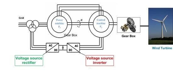
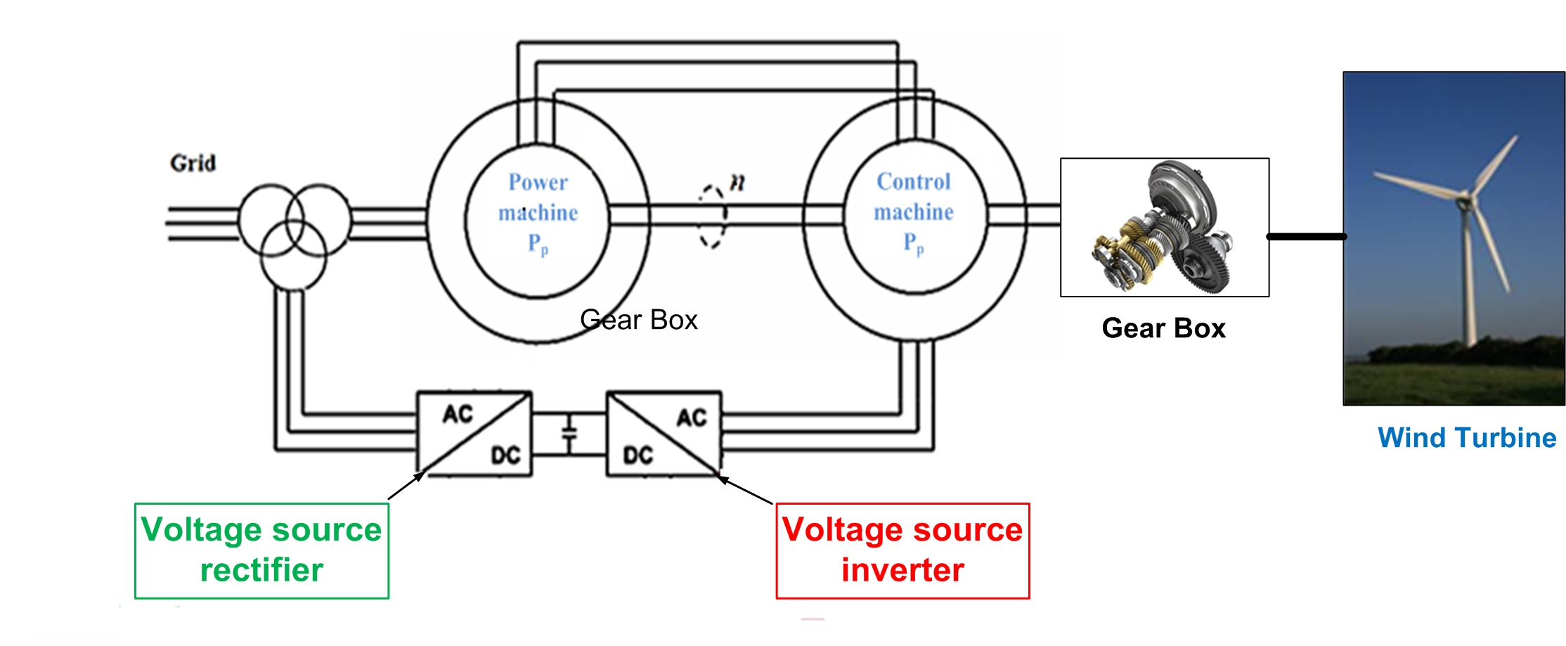
2.2. Brushless Doubly-Fed Twin-Stator Induction Generator (BDFTSIG) Model

2.2.1. Voltage Equations

In the machine model, there is a relative motion between the stator of both the power and control machine. The general relationship between these quantities as well as the electrical speed of the rotor for the system of frequency ( f s = 50 Hz) is given by [28]:
ω p = 2 π f s ω r = ω p ω m p p ω c = ω p ω m ( p p + p c )
Due to the back to back connection, the rotor currents produced by the two machines join in the subtractive technique, and the rotor voltages have the same signs [26,27,28], i.e. i r = i r p = i r c and v r = v r p = v r c .
In order to analyze the steady-state model, it is assumed that all vectors are rotating in the rotor reference frame with angular frequency equal to the power machine stator angular frequency ω p . The slips of two machines, power machine and control machine, are:
s p = ω p p p ω m ω p
s c = ω c p p ω m ω c
The steady state per-phase equivalent circuit is shown in Figure 3. Because the two considered machines are assumed to be identical, the sum of rotor resistances and the sum of rotor leakage inductances are modeled in the rotor circuit.

2.2.2. Flux Equations

ψ s p ψ r ψ s c = L s p L m p 0 L m p L r L m c 0 L m c L s c I s p I r I s c
Hence,
I s p = ψ s p   L m p I r L s p
I r = ψ r   L m p I s p + L m c I s c L r
I s p = L r L s p L r L m p   2 ψ s p   L m p L s p L r L m p   2 ψ r L m p L m c L s p L r L m p   2 I s c  
Equation (12) shows how complex the BDFTIG system is, and confirms that there exists an electrical coupling between the control machine stator through the rotor to the power machine stator and shows that the power machine stator current is determined by power machine stator flux, rotor flux and control machine stator current. However, the power machines stator flux ψ s p has almost constant value due to the stiff grid connection assuming small stator winding resistance [30,32].

2.2.3. Torque Equation

The mechanical model of the BDFTSIG is derived by applying the frictions and inertias of the power and control machines [31,32]:
( J p + J c ) d ω m d t = T e F p + F c ω m T L
where: J p Moment of inertia of the power machine, J c Moment of inertia of the control machine, F p Friction coefficient of the power machine, F c Friction coefficient of the control machine, T e Electromagnetic torque of the machine, and T L Load torque.

2.2.4. Dynamic Equations

The main power machine is connected directly to the grid and the control machine interfaced to the grid through fractional back-to-back power converter. The rotor circuits are connected in such a way that allows the production of additive torques, as to increase the overall torque rating of the generator and to give the system wide operational range [32], with the back-to-back connection, the behavior of each individual machine is described by the following:
v s p = ( R s p + L s p s + j ω p ) i s p + L m p s + j ω p i r p
v r p = ( R r p + L r p s + j ω r ) i r p + L m p s + j ω r i s p
v s c = ( R s c + L s c s + j ω c ) i s c + L m c s + j ω c i r c
v r c = ( R r c + L r c s + j ω c ) i r c + L m c s + j ω c i s c
where,
v s p the stator voltage of the power machine, i r c the stator current of the control machine, v r p the rotor voltage of the power machine, L   s p , L   s c Stator leakage inductance of the power and control machine, v s c the stator voltage of the control machine, L   r p , L   r c rotor leakage inductance of the power and control machine, v r c the rotor voltage of the control machine, L   m p , L   m c mutual inductance of the power and control machine, i s p the stator current of the power machine, i s c the stator current of the control machine, and i r p the rotor current of the power machine
Converting the three-phase machine to its two-phase equivalent and selecting the appropriate reference frame, all the time varying inductances in both the stator and the rotor are eliminated, allowing for a simple yet complete dynamic model of the electric machine. The best choice in this case would be the synchronously rotating reference frame attached to the power machine stator as it allows transformation of all the voltages and currents into equivalent DC values under steady state operation.
  • D s p / Q s p stand for the stationary reference frame attached to the power machine stator
  • D e / Q e is the synchronous reference frame rotating with speed ω e . The transformation angle for the stator quantities is the synchronous angle, which for a ‘stiff’ grid always rotates at a constant speed.
  • D r / Q r is the d-q reference frame attached to the rotor. This stationary frame, however, is rotating with respect to the stator stationary reference frame at an angular speed of ω r .
Converting the three-phase machine to the two-phase equivalent circuit by applying the standard Park’s and Clark’s transformation, the resulting model becomes as shown in Figure 4b,c.
The resulting BDFTIG dynamic electric model is given by [32,33,34,35,36]:
v s p q v s p d v r p q v r p d v s c q v s c d = R s p + s L s p ω p L s p s L s p ω p L m p 0 0 ω p L s p R s p + s L s p ω p L m p s L m p 0 0 s L m p ω r L m p R r + s L r ω r L r s L m c ω r L m c ω r L m p s L m p ω r L r R r + s L r ω r L m c s L m c 0 0 s L m c ω c L m c R s c + s L s c ω c L s c 0 0 ω c L m c s L m c ω c L s c R s c + s L s c i s p q i s p d i r q i r d i s c q i s c d

3. Proposed Indirect Vector Control

The primary function of the BDFTSIG controller is to extract power at any given operational point of the wind turbine. The maximum power that is extracted at any given wind velocity is achieved by means of maximum power point tracking (MPPT) algorithm based on the optimized power coefficient curve of the wind turbine [13]. Hence, the controller’s main target is to follow the desired reference speed generated by MPPT as well as allowing adjustable reactive power flow. As shown in Figure 1, the bidirectional power converter implemented to achieve the variable speed operation consists of:
  • Voltage source pulse width modulated (PWM) rectifier acting as boost converter
  • Voltage source PWM inverter used to adjust the control machine of the BDFTSIG.
The controlling topology of each of the PWM converters is as follows:

3.1. Grid Side Converter Control

Grid side converter is mainly a voltage source rectifier (VSR) keeping the load DC-link voltage at a desired reference value, using a feedback control loop. This reference value, has to be high enough to keep the diodes of the converter blocked. Once this condition is satisfied, the DC-link voltage is measured and compared with the reference. The error signal generated from this comparison is used to switch ON and OFF the valves of the VSR. In this way, power can bi-directionally flow through the AC source according to the DC-link voltage value. The main circuit topology is shown in Figure 5a. According to Grid-Voltage-Oriented vector control strategy, a dual-channel closed-loop control strategy for VSR is presented, where id, iq are active and reactive power component [36]. For active power control, the DC-link voltage control loop is regarded as the outer-loop. The error between DC-link voltage command and feedback voltage passes the proportional-integral (PI) regulator, and the result is active power current command i d .
The active power control ensures the DC-link voltage remains constant. For reactive power control, it aims to accomplish the system’s input power factor near unity. Therefore, the reactive current ( i q ) should be controlled to zero all the time. The dynamic model of the VSR is expressed by the following equations [30,31,32,33]:
V q V d = R I q I d + s L I q I d + ω e L I d I q + V q V d
P = 3 2 V d I d + V q I q
Q = 3 2 V q I d V d I q
According to grid voltage orientation:
V d c I i n = 3 2 V d I d
The block diagram of the VSR controller is shown in Figure 5b.

3.2. Machine Side Converter Control System

The machine side converter is mainly a voltage source inverter (VSI). The converter controller design is a critical aspect. When connected to the grid, the output voltage and frequency of the power machine are fixed. The proposed indirect vector control scheme controls the power flow through the power machine (reactive power, Q p and active power P p ). The P p and Q p of the power machine stator can be dynamically controlled via the rotor circuit from the stator of the control machine, by adjusting the phase and magnitude of the stator current in the control machine (excitation current) [18,35,36]. The active and reactive power flow equations for the power machine are:
P p = 3 2 ( v s p q i s p q + v s p d i s p d )
Q p = 3 2 ( v s p q i s p d + v s p d i s p q )
Aligning the d-axes with the flux vector of the power machine allows for the further simplification of Equation (23). The power machine flux vector is perpendicular to the power machine voltage vector, therefore the d component of the stator voltage of the power machine ( v s p d ) and the q-component of the flux vector of power machine ( ψ s p q ) always remains at zero. The active and reactive power equations would be as follows [32,33,34,35,36]:
P p = 3 2 ( v s p q i s p q )
Q p = 3 2 ( v s p q i s p d )
The power machine reactive power ( Q p ), is controlled by the d-axis current of the power machine ( i s p d ) while the power machine active power ( P p ), is controlled by the q-axis current of the power machine ( i s p q ).
i s p d = ( ψ s p d L r ) L m p ψ r d L m p L m c i s c d L s p L r L m p 2
i s p q = L m p ψ r q L m p L m c i s c q L s p L r L m p 2
Substituting the equations of i s p q and i s p d (Equations (27) and (28)) in the active and reactive power equations (Equations (25) and (26)) yields:
P p = 3 2   v s p q   ( L m p L s p L r L m p 2   ψ r q   +   L m p L m c L s p L r L m p 2   i s c q )
Q p = 3 2   v s p q   ( L r L s p L r L m p 2   ψ r d     L m p L s p L r L m p 2   ψ r d     L m p L m c L s p L r L m p 2   i s c d )
From Equation (29) it can be realized that the active power P p depends on the q-axis stator current component of the control machine ( i s c q ) and in Equation (30) the reactive power Q p depends on the d-axis stator current component of the control machine ( i s c d ). The structure of the proposed indirect VSI vector controller allows for the outer speed control loop producing the required reference current signal ( i s c q ). The ( i s c d ) reference signal can be obtained directly from the desired reactive power command. For frame transformations, the angle between CM stator and PM stator synchronous frames is given by:
θ c = θ p p p + p c θ m
The complete proposed system illustration is shown in Figure 6.

4. Simulation Results

In order to simulate the performance of the proposed indirect vector controller for the BDFTIG-based wind turbine system, it was necessary to develop a comprehensive model of the whole system that would be flexible enough to repeat the performance characteristics under different operational conditions. It was created using SIMULINK including elements from the MATLAB software package.
The system consisted of the three major components:
  • The complete modelling of the BDFTIG with bi-directional converter;
  • The controllers for the BDFTIG;
  • The aerodynamic model of the wind turbine.
The parameters used for simulation purposes are defined in Table 2.
The following subsections describe the generation of the MATLAB/SIMULINK blocks for the system under investigation.

4.1. Turbine Aeromechanical Model Simulation

As previously mentioned, the main purpose of the BDFIG controller is to allow power extraction at any given operational point of the wind turbine. The method used to extract maximum power at any given wind speed is to implement maximum power point tracking (MPPT) algorithm based on the optimized power coefficient curve of the wind turbine. Thus the maximum power extraction for any given wind speed is only possible at an optimized turbine speed. The curves of the wind turbine whose parameters are given in Table 1 at different wind speeds are given in Figure 7a.
By utilizing the power signal feedback (PSF) MPPT technique which uses a 2D look-up table where the optimal powers versus the rotating-speed characteristics [37,38,39,40,41] together with the turbine curve, one can implement the controller scheme to achieve the MPP curve shown in the figure above. This maximum power tracking is achieved through the manipulation of the turbine electrical torque by controlling the excitation of the control machine in order to control the loading of the power machine on the grid. The aeromechanical performance of the wind turbine using the standard block provided with the Simulink’s SimPowerSystems block set as shown in Figure 7b.

4.2. Voltage Source Rectifier (VSR) Control Simulation

Starting with the VSR controller, whose purpose is to:
  • Perform the function of the boost-rectifier;
  • Maintain constant DC-link voltage;
  • Exchange the energy between the grid and the DC-link regardless of the load connected to the VSI side (the control machine in our system).
The reference voltage signal was set to 500 V, while the rectifier was forced to operate at a unity power factor. The performance of the VSR is illustrated as shown in Figure 8.
As seen from Figure 8a the controller was able to maintain a constant DC link voltage at the required value of 500 V. The error between DC-link voltage command and feedback voltage passes the PI regulator, the result is active power current command i d r . The active power control ensures the DC-link voltage remain constant. Accordingly, the d-axis current tracks the reference value to fulfill the required DC-link voltage as seen in Figure 8b.
For reactive power control, it aims to accomplish the system’s input power factor near unity. Therefore, the reactive current should be controlled to zero all the time. The controller was able to maintain the rectifier operation at unity power factor. This is clear in Figure 8c,d where the reactive power absorbed by the rectifier is equal to zero and the q-axis current accurately tracks the reference value i q r = 0 .

4.3. Voltage Source Inverter (VSI) Control Simulation

The controller of the machine side converter can be implemented using Speed control ( ω Q ) strategy: The wind turbine operation in this strategy requires the speed and reactive power control for maximum power extraction and reactive power support for the grid. These two requirements are independent. Hence they are required to be decoupled. Thus, the maximum power extraction for any given wind speed is only possible at an optimized turbine speed. The command signals of the VSI speed controller include the desired turbine speed, which is directly related to the active power produced by the BDFTIG generated as previously mentioned from the power signal feedback (PSF) MPPT technique, and the required reactive power for the generator to maintain an appropriate power quality to the grid. The system performance under speed control will be investigated in the following cases:
(a)
Variable wind speed and consequently the turbine speed command signal will be variable to obtain the maximum power extraction at the corresponding varying wind speed, while the reactive power command signal remains constant at 0 VAr to achieve a unity power factor operation.
(b)
Constant wind speed and hence the turbine speed command signal will be kept constant at the value that achieves maximum power extraction at this wind speed, while the reactive power command signal varies from −500 VAr (leading p.f), to 0 VAr (unity p.f) to 500 VAr (lagging p.f). This investigation shows the degree of independence between the speed, which is in direct proportion with the active power flow, and the reactive power flow in the BDFTIG.
  • First case: Variable speed command at constant reactive power reference:
The simulation is carried out on a fully-detailed model when the WT operates at:
Sub-synchronous speed: The initial per unit rotor speed ω m = 0.95 p.u with wind speed input = 9.6 m/s.
Super-synchronous: The initial per unit rotor speed ω m = 1.1   p.u with wind speed input = 10.8 m/s.
These two operating points are shown on the MPP curve of the wind turbine as shown in Figure 7a.
As previously mentioned in Table 1:
f = 50 H z ,   p p = 3   p o l e   p a i r s   ,   p c = 2   p o l e   p a i r s
Hence the rated synchronous speed:
ω s r = 60   f p p p + p c = 60 50 3 + 2 = 600   r p m
Consequently, to study the controller performance for this case at sub and super synchronous rotor speed levels:
The speed reference at wind speed 9.6m/s is = 0.95 x 600 = 570   r p m ; and
The speed reference at wind speed 10.8m/s is = 1.1 x 600 = 660   r p m .
The rotor speed command is derived at wind speed and the corresponding mechanical power output of the wind turbine based on the WT characteristic curves shown in Figure 7a, whereas the reactive power command is imposed to be 0 VAr. Both ω m and Q commands are compared to the corresponding measured values to obtain error signals which are fed to PI controllers whose outputs are the CM stator current commands i q c and i d c , respectively. These current commands are consequently compared to their corresponding measured values producing error signals driving the PI current controller generating the d - q MSC voltage commands being fed to the PWM module. The system simulation results are as shown in Figure 9 and Figure 10. The reactive power reference command remains unchanged throughout the simulation time and is kept constant at 0 VAr, while the speed command is 570 rpm from t = 0 s to t = 2.5 s during which the wind speed is 9.6 m/s and then the reference speed jumps to 660 rpm from t = 2.5 s to t = 5 s while the wind speed is 10.8 m/s. As can be seen in Figure 9a the speed of the machine accurately tracks the reference speed proving the ability of the speed controller proper reference tracking. In Figure 9b the q-axis control machine actual current ( i q c ) accurately tracks the reference current ( i q c ). The q-axis control machine current ensures the optimal speed tracking. Accordingly, the q-axis current tracks the reference value to fulfill the required speed command.
Similarly, in Figure 9c the actual power machine reactive power ( Q p ) follows the reactive power command ( Q p ) and the error between the reference and actual reactive power passes the PI regulator, the result is the d-axis control machine current command i d c . Accordingly, the d-axis current tracks the reference value to fulfill the required reactive power command as seen in Figure 9d. Since the rotor speed is directly proportional to the power flow in the power machine hence the power machine varies as the speed changes. As seen in Figure 9e the power machine power changes from 2400 W to 2750 W as the speed changes from 570 rpm to 660 rpm, respectively. Also the power machine current increases respectively as the power machine power increases as seen in Figure 9f.
The input mechanical power from the wind turbine changes from 2250 W to 3200 W as the wind speed changes from 9.6 m/s to 10.8 m/s, respectively, as seen in Figure 10a and the input torque changes from −25 Nm to −32.5 Nm as in Figure 10b (the negative sign is for the generator mode of the power machine).
The control machine power also varies as the speed changes. Not only does the magnitude of power change but also the direction of power flow. The power of the control machine at speed 570 rpm is 625 W whilst the power through the control machine changes to −225 W at speed 660 rpm as in Figure 10c, i.e., the direction of power flow is into the control machine while the BDFTIG is operating in the sub-synchronous mode and the power flow is out of the control machine during super-synchronous operation. As can be noticed from the magnitude of the control machine power its value is a fraction of the rated power of the machine. This is one of the advantages of the BDFTIG system as the control machine absorbs a fraction of the rated power and hence the power electronic converter only has to handle a fraction of the total machine power. The remaining power is fed to the grid directly from the stator of the power machine. Therefore, the cost of the converter is low when compared with other variable-speed drives.
The rotor speed is directly proportional to the CW frequency, and its absolute value increases when the rotor speed deviates from natural synchronous rotor speed. From Figure 10d the frequency of the control machine current increases from sub-synchronous to super-synchronous operation mode.
Figure 10e shows the variation in the grid power in both cases from sub-synchronous to super-synchronous operation mode. The grid power changes from 1775 W to 2975 W, respectively, whilst the grid reactive power is kept constant at 0 VAr as in Figure 10f.
  • Second case: Constant speed command at variable reactive power reference:
In this case, the system is speed controlled, but this time the rotor speed is derived at wind speed 9.6 m/s and the corresponding mechanical power output of the wind turbine based on the WT characteristic curves (i.e., the rotor speed is imposed at 570 rpm), whereas the reactive power command is varied from −500 VAr (capacitive) to 0 VAr (resistive) to 500 VAr. This test is performed to illustrate an important benchmark for the performance of the proposed controller scheme which is the degree of the independence between the active and reactive power flows in the BDFTIG (complete decoupling). The results of this test are shown in Figure 11 and Figure 12. This degree of independence can be determined by looking at the impact that the change in power machine reactive power has on the speed of the generator. Figure 11c shows that the reactive power consumption changes from −500 VAr to 0 VAr at 1.5 s and then changes to +500 VAr at 3 s. It shows how the actual reactive power of the power machine accurately tracks the reactive power command. Figure 11a shows how the speed of the generator remains constant at 570 rpm with the change in the reactive power. In Figure 11e,f the power machine power remains constant at 2400 W and consequently there is no variation in the power machine current. Figure 12a shows that the input mechanical power remains constant at 2250 W. Figure 12b shows a slight variation in the active power consumption of the control machine with the change in the reactive power command from 625 W to 750 W at 1.5 s and to 875 W at 3 s. Figure 12c illustrates the control machine current. It can be observed that there is no change in the frequency of the control machine current since the speed of the generator remains constant at 570 rpm.

5. Experimental Verification

A practical implementation of the BDFTIG WECs control system is presented to verify the results obtained in the previous section, using a scaled down prototype system. A photograph of the system implemented for experimental verification is shown in Figure 13a and the system block diagram is illustrated in Figure 13b.
The prototype of the wind turbine consisted of:
  • Two identical 1.5 kW wound rotor induction machines forming the BDFTIG induction machine. These were mechanically coupled in the back to back topology, while their rotors were interconnected without any phase inversion between them.
  • The wind turbine itself was emulated using another induction machine equipped with a commercial alternating current (AC) drive to imitate wind speed variation.
  • The bidirectional power converter with the controller controlled by a Digital Signal Processor (DSP) controller based on Texas Instruments’ F28335 Delfino DSP board.
  • The voltages and currents of each stator phase are measured by LEM LV25-p and LEM LA 55-p transducers, respectively.
  • In order to get the value of the angle required for the abc-dq transformation in the controller, a digital photo tachometer (MODEL HPT-100A) was used and a special signal conditioning circuit was designed to provide the data required for the mechanical speed and angle ( ω m , θ m ) calculation.
The power machine of the BDFTIG was directly connected to the 220 V/50 Hz power grid, while the control machine was connected to the grid through the bidirectional converter and an isolation transformer. Kindly see Appendix A.1 for BDFTSIG experimental realization.

5.1. Control Implementation

The controller algorithm implemented for this system is divided into two independent but essential parts to coordinate the operation of the PWM rectifier (grid-side converter, GSC) and the PWM inverter (machine-side converter, MSC).
The sequence of operation of the controller required to achieve this coordination is as follows:
  • First, the grid side converter was energized and operates in the uncontrolled rectifier mode under no-load conditions.
  • Second, the VSR is activated and it boosts the DC voltage to the required level (in our case the DC voltage is kept at 100 V).
  • Third, the VSI was turned on and left in the idle mode, effectively producing a short circuit at the control machine windings.
  • Fourth, with stabilization of the DC voltage, the power machine stator windings are energized, bringing the BDFTIG to its synchronous speed.
  • When the generator reached steady state operation the VSI controller became fully engaged driving the BDFTIG to whatever the reference speed was set to be. The reference speed was limited to ± 25% of the synchronous speed to allow for a safe operation of the BDFTIG.
  • The turn off sequence for the converter was the opposite of the start-up procedure, allowing for gradual disconnection of the machine and the converter.
The performance of the BDFTIG and the bidirectional power converter was evaluated at several load conditions, as well as in both the sub-synchronous and super-synchronous regions of operation. The initial experiment involved a no-load operation to check the validity of the BDFTIG model operation and then the loading conditions were tested.

5.2. Grid-Side Converter (GSC) Experimental Results

The GSC is a 3-phase inverter module which consists of an insulated gate bipolar transistor (IGBT) module, (IRAMY20UP60B). International Rectifier’s IRAMY20UP60B is a 20 A, 600 V integrated power hybrid IC with internal shunt resistor for appliance motor drive applications such as air-conditioning systems and compressor drivers as well as for light industrial application. Synchronous reference frame control is selected for PWM VSR operation, which transforms the 3-phase supply grid currents i a b c g r i d into a reference frame that rotates synchronously with the 3-phase grid voltages v a b c g r i d . The control in this case requires two loops; an inner loop for grid current control and an outer loop for DC-link voltage control, as shown in Figure 13b. For proper operation of the PWM-VSI, the DC-link capacitor voltage, V d c must be controlled to comply with the necessary output power needed to be injected into the grid.
For grid current control, the three-phase grid currents i a b c g r i d are transformed into instantaneous active I d and reactive I q components using a rotating frame synchronous with the positive sequence of the system voltage. The dq- axes grid currents, I d and I q are decoupled to independently control the active and reactive power components. For decoupled control, the fundamental phase angle θ g of grid voltage, v a g r i d used by the abc-dq transformation has to be locked with the PLL technique. In the inner active current control loop, I d is set in relation to the DC-link voltage, V d c l i n k which is controlled via the outer control loop. Controlling I d controls the active power in relation to the V d c l i n k . I q is compared to a zero reference for unity power factor operation. Using PI controllers, the output of both grid current loops v d i and v q i , are transformed back to synchronous rotating quantities to issue the gating signals for the GSC. In Figure 14 the output waveforms of the GSC for the experimental setup are presented.
From the figures below it is clear that the DC voltage link is kept constant at 100 V as shown in Figure 14a and the rectifier is operating at unity power factor as seen from Figure 14b.

5.3. Machine-Side Converter (MSC) Experimental Results

The MSC converter is similar in design to the GSC. It is also a 3-phase inverter module which consists of an insulated gate bipolar transistor (IGBT) module, (IRAMY20UP60B). However, the control algorithm for the MSC is different than that of the GSC.
As previously mentioned, the wind turbine operation requires the speed control and reactive power control for maximum power extraction and reactive power support for the grid. These two requirements are independent. Thus the maximum power extraction for any given wind speed is only possible at an optimized turbine speed.
Hence, the experimental procedure aims at verifying the ability to independently control the speed of the machine and the reactive power flow.
The command signals of the VSI speed controller include:
(a)
The desired turbine speed, which is directly related to the active power produced by the BDFTIG generated from the power signal feedback (PSF) MPPT technique.
(b)
The required reactive power for the generator to maintain an appropriate power quality to the grid.
The system performance is investigated under different operating conditions according to the following sequence:
i.No load test:
• Test (1):
The testing of the BDFIG was carried out with no load test. In the first test the power machine is connected to the grid and the stator windings of the control machine are shortened, without any input torque to the BDFTIG. Under these operating conditions the BDFTIG rotates at the synchronous speed (750 rpm). Figure 15a,b illustrate the output waveforms of the system at no load. It is clear from Figure 15a that the speed of the machine is held constant at the synchronous speed 750 rpm, while the current and voltage relation is as shown in Figure 15b. Concerning the power flow of the machine, the power machine absorbs from the grid an amount of reactive power equal to 930 VAr as illustrated in Figure 15d. This result was recorded by a Fluke 1730 Energy logger. The energy logger indicates a negative active power by recording a negative power factor value. The clamp meters used for current measurement of the energy logger were connected in such a way that the positive convention of the current was in the direction out of the power machine to the grid. The recorded value of the power was (−125 W) which means that the power machine absorbs active power from the grid of a value (125 W) as shown in Figure 15c.
• Test (2):
Another test was then performed where the speed reference was reduced to 470 rpm while the reactive power command was equal to 930 VAr. This test was carried out to show the ability of the control system to control the speed and the reactive power of the system independently. The system performance is illustrated in Figure 16. It can be seen that the speed of the machine falls from the synchronous speed of 750 rpm when the control machine terminals are short circuited to 470 rpm when the MSC controller is applied and the necessary voltage is injected to the control machine under the no load condition (no input torque is applied to the BDFTIG) as shown in Figure 16a.
The current and voltage waveforms are as shown in Figure 16b. Concerning the power flow of the machine, the power machine absorbs active power from the grid of a value (110 W) as shown in Figure 16c. The power machine absorbs from the grid an amount of reactive power equal to 930 VAr as illustrated in Figure 16d. It can be observed that the reactive power consumption remains constant with the change in speed from 750 to 470 rpm which shows the decoupling between the speed and the reactive power control.
• Test (3):
The third test was performed to evaluate the response of the system to the change in the reactive power flow by channeling a portion of the reactive power through the control machine, while the generator speed remained constant at 470 rpm with no load. The PWM inverter was set to reduce the power machine reactive power to 33% of the nominal reactive power. The results of this test are shown in Figure 17. It can be seen that the speed of the machine falls from the synchronous speed of 750 rpm to 470 rpm by applying the necessary voltage to the control machine under the no load condition (no input torque is applied to the BDFTIG) as shown in Figure 17a. The current and voltage relation is as shown in Figure 17b. Concerning the power flow of the machine, the power machine absorbs from the grid an amount of active power equal to 100 W which is similar to the previous test since the speed command remained constant and consequently the amount of active power flow is the same as in the previous test as shown in Figure 17c. The reactive power flow is equal to 620 VAr equal to the reactive power command which was reduced by 33% as illustrated in Figure 17d. In this test, contrary to the previous test, the speed remains constant while the reactive power flow is controlled to be reduced from 930 VAr to 620 VAr. Again the decoupling between the reactive power and speed control is verified.
ii.Load Test:
• Load Test 1:
Once the proper operation of the converter has been established, the system was loaded by driving the prime mover to produce the required amount of torque. Initially the controller was disabled and the control machine stator windings are shorted, allowing the system to achieve the super-synchronous operation at 776 rpm. In this configuration the BDFTIG was acting as a simple induction generator providing the base values for power flow. The system performance under the above conditions is illustrated in Figure 18.
The speed of the BDFTIG is at 776 rpm as shown in Figure 18a. The current and voltage relation is as shown in Figure 18b. It should be noted that the active power is now flowing out of the power machine, with the angle between the current and voltage calculated to be 105 degrees. The active power flow increased to 255 W as illustrated in Figure 18c. It can be seen that the power recorded by the fluke energy logger is now of a positive sign which indicates the power reversal. (i.e., the power is flowing from the power machine to the grid).
The reactive power consumed by the power machine follows the new reference of 1110 VAr as shown in Figure 18d. Hence, this test ensures the capability of the proposed controller to achieve decoupled speed and reactive power tracking under varying speed and reactive power references.
• Load Test 2:
With the base values established and the torque kept constant, another test was performed on the system to evaluate the system performance when the speed falls from the super-synchronous speed.
In this test the speed reference of the BDFTIG was set to 700 rpm-well below the natural speed as seen from Figure 19a, while requesting constant steady reactive power flow to the power machine stator. The current and voltage relation is as shown in Figure 19b. It can be shown that the machine follows the speed reference and falls to the subsynchronous speed of 700 rpm. Consequently, the active power injected to the grid increases from 255 W to 350 W as shown in Figure 19c. At the same time, the reactive power consumption remained constant at 1110 VAr as well, indicating the decoupled nature of the control algorithm as illustrated in Figure 19d.

6. Results Discussion

In this section: results are analyzed and discussed regarding the proposed indirect vector control technique for WECS based on BDFTSIG. The proposed control technique is mainly utilized to control both the GSC and MSC. Each converter requires specific features that the controller must offer. The proposed controller has been attested under various operating conditions and modes to assure its functionality and illustrate its superior performance.

6.1. Grid-Side Converter Results

The proposed control technique succeeds in fulfilling the two associated main tasks: (i) DC-link voltage control and (ii) unity power factor grid integration via the proposed active-reactive power control. This can illustrated as shown in Figure 8a,c for the DC-link voltage and rectifier reactive power, respectively, where it can be shown how the proposed control technique achieves the required DC-link voltage level and assure near-zero reactive power drawn from the grid. An experimental emphasis on the proposed control superior performance for the GSC is illustrated in Figure 14 as well.

6.2. Machine-Side Converter Results

The proposed indirect vector control scheme controls the power flow through the power machine (reactive power, Q p and active power P p ). The P p and Q p of the power machine stator can be dynamically controlled via the rotor circuit from the stator of the control machine, by adjusting the phase and magnitude of the stator current in the control machine. The critical aspect that the proposed control technique offer is its decoupling feature, as it can control both the active and reactive power of the power machine independently at both sub-synchronous and super-synchronous rotor speed. The proposed control technique succeeds in varying the power machine active power while maintaining constant reactive power for both sub-synchronous and super-synchronous rotor speed is illustrated in Figure 9 and Figure 10. In addition, for the whole speed range, the proposed controller efficiently varies the power machine reactive power while attaining constant active power as shown in Figure 11 and Figure 12. Consequently, the decoupled feature for the proposed control technique is proven by these extensive simulation results. The rigorous experimental results contribute to more emphasis on the claimed proposed control technique superior performance. The decoupling feature is illustrated through Figure 15, Figure 16 and Figure 17 where the system is controlled for three cases (i) no load sub- and super-synchronous rotor speed, (ii) varying speed(active power) while preserving constant reactive power and (iii) varying the reactive power while maintaining constant speed. A similar assessment was performed at the loading conditions shown in Figure 18 and Figure 19.

7. Conclusions

In this paper, BDFTSIG has been presented as a viable solution for WECS. Complete machine mathematical modelling has been illustrated showing the possibility of controlling the power machine active and reactive power via the control machine rotor currents using a reduced power rating back-to-back converter. An indirect vector control scheme has been proposed for a BDFTSIG based WECS. The proposed technique shows decoupled control capabilities at varying grid connection loading conditions. The presented control offers enhanced transient performance in addition to minimized steady state oscillations. The proposed indirect vector control shows independent control of both the reactive power flow and speed. The experimental results obtained verify the proposed controller scheme, which allows wide operational range grid integration and reactive power control. In addition to the superior performance, the proposed indirect vector control offers simplified implementation compared to recently evolved BDFTSIG control techniques due the reduced control loops in addition to its inherit tolerance to machine parameters’ variations as clarified in Appendix A.2.

Author Contributions

Conceptualization, A.A.H. and A.K.A.; methodology, A.K.A.; software, M.I.A.; validation, A.K.A. and M.I.A.; formal analysis, A.K.A. and M.I.A.; investigation, A.K.A. and M.I.A.; resources, M.I.A.; data curation, M.I.A.; writing—original draft preparation, M.I.A.; writing—review and editing, A.K.A. and M.I.A.; visualization, M.I.A.; supervision, A.K.A. and A.A.H. All authors have read and agreed to the published version of the manuscript.

Funding

This research received no external funding.

Conflicts of Interest

The authors declare no conflict of interest.

Nomenclature

P w i n d kinetic power of air stream
ρ Air Density
V Wind Linear Velocity
λ Tip Speed Ratio (TSR)
A Turbine Blade Swept Area
P m The mechanical power
C p performance coefficient of turbine blades
β Blade Pitch Angles
R Wind Turbine blade radius
ω m rotor speed
V c i Cut-in wind velocity of the turbine
V n o m Nominal wind velocity of the turbine
c 1 . . c 9 Characteristic constants for each wind turbine.
ω p Angular speed for power machine, (r/s)
ω r Rotor frequency, (r/s)
ω m Shaft mechanical speed, (r/s)
ω c Angular speed for control machine, (r/s)
f s Grid frequency
p p   ,   p c Pole Pairs for Power and Control machines
i r p Rotor current of the power machine
i r c Rotor current of the control machine
v r p Rotor voltage of the power machine
v r c Rotor voltage of the control machine
s slip
L   s p , L   s c Stator leakage inductance of the power and control machine
L   m p , L   m c Mutual inductance of the power and control machine
L   r Rotor-inductance of the power and control machine
ψ s p power machine stator flux
ψ r rotor flux
ψ s c control machine stator flux
i s p Stator current of the power machine
i s c Stator current of the control machine
i r Rotor current of the power and control machine
J p Moment of inertia of the power machine
F p Friction coefficient of the power machine
T e Electromagnetic torque of the BDFTIG machine
J c Moment of inertia of the control machine
F c Friction coefficient of the control machine
T L Load torque
v s p Stator voltage of the power machine
v s c Stator voltage of the control machine
v s p q q-axis stator voltage of the power machine
v s p d d-axis stator voltage of the power machine
v r p q q-axis rotor voltage of the power machine
v r p d d-axis rotor voltage of the power machine
i s p q q-axis stator current of the power machine
i s p d d-axis stator current of the power machine
i r p q q-axis rotor current of the power machine
i r p d d-axis rotor current of the power machine
v s c q q-axis stator voltage of the control machine
v s c d d-axis stator voltage of the control machine
v r c q q-axis rotor voltage of the control machine
v r c d d-axis rotor voltage of the control machine
i s c q q-axis stator current of the control machine
i s c d d-axis stator current of the control machine
i r c q q-axis rotor current of the control machine
i r c d d-axis rotor current of the control machine
V a Generator phase voltage
V a Bridge converter voltage controllable according to the demanded DC voltage level
I a Load current
i a Line current
I d c Converter DC output current
V d c Converter DC output controlled voltage
θ g Grid voltage phase-angle
v a ,   v b ,   v c instantaneous three, phase-to-neutral grid voltages
V d Rectifier d-axis voltage
V q Rectifier q-axis voltage
I d Rectifier d-axis current
I q Rectifier q-axis current
P p Active Power of the Power Machine
Q p Reactive Power of the Power Machine
ψ s p q q-axis stator flux of the power machine
ψ s p d d-axis stator flux of the power machine
ψ r p q q-axis rotor flux of the power machine
ψ r p d d-axis rotor flux of the power machine
ψ s c q q-axis stator flux of the control machine
ψ s c d d-axis stator flux of the control machine
ψ r c q q-axis rotor flux of the control machine
ψ r c d d-axis rotor flux of the control machine
θ p Power Machine angular position
θ c Control Machine angular position

Appendix A

Appendix A.1. BDFTSIG Experimental Realisation

Figure A1. Cascaded induction machines implementation used in this article.
Energies 13 04174 g0a1
Figure A2. Single frame implementation using two windings in stator and nested rotor [27].
Energies 13 04174 g0a2

Appendix A.2. Parameter Sensitivity Analysis

In this section, rigorous investigation of the proposed controller parameter sensitivity analysis is performed. As the proposed controller is divided into GSC controller and MSC controller, the analysis is divided into two subsections as well:

Appendix A.2.1. GSC Controller Parameter Sensitivity Analysis

The GSC function is mainly to stabilize the DC-link voltage and achieve a near unity power factor operation. The assessment of the proposed converter tolerance to system parameter variation is illustrated. As the GSC accommodates the grid side filter parameters, Rg and Lg, the system is simulated six times where the grid filter resistance and inductance witness a wide range of variation. Filter resistance is varied from 0.1 p.u to 5 p.u while the inductance is changed from 0.5 p.u to 2 p.u. It can be shown from Figure A3 that the proposed controller shows high tolerance to the grid filter resistance variation regarding the controlled DC-link voltage and grid current zero-crossing with grid voltage. The reason behind this enhanced performance is that the decoupling equations of the proposed GSC controller eliminate the grid filter resistance from the controller design, Equations (19) and (20). It can be noticed that the grid filter inductance variation has a noticeable effect on the DC-link voltage transient performance due to its dependency on the filter inductance value, Equations (20) and (21). Yet, the steady-state DC-link voltage performance is quite stable. In addition, the output near-sinusoidal grid current ensure minimal deviation from the designed zero-crossing and decrease the dependency on the grid filter inductance, hence the unity power factor is guaranteed for the whole range of operation.
Figure A3. Grid-side converter (GSC) waveforms at varying grid filter resistance: (a) DC-link voltage, (b) grid current.
Energies 13 04174 g0a3
Figure A4. GSC waveforms at varying grid filter inductance: (a) DC-link voltage, (b) grid current.
Energies 13 04174 g0a4aEnergies 13 04174 g0a4b

Appendix A.2.2. MSC Controller Parameter Sensitivity

For the MSC proposed indirect vector control, the reference active and reactive power command is controlled via the stator currents of the control machine as described in Section 3:
P p = 3 2   v s p q   ( L m p L s p L r L m p 2   ψ r q   +   L m p L m c L s p L r L m p 2   i s c q )
Q p = 3 2   v s p q   ( L r L s p L r L m p 2   ψ r d     L m p L s p L r L m p 2   ψ r d     L m p L m c L s p L r L m p 2   i s c d )
Hence, it can be shown that the proposed indirect vector control outweighs the direct vector control as it offers no dependency on the BDFTSIG stator and rotor resistance dependency as clarified in Equations (A1) and (A2).
For practical analysis, one must consider the fact that the leakage inductance value can be ignored in comparison to mutual inductances. Consequently:
L s p L r L m p 2 = L l s p + L m p L l r + L m r L m p 2 = L l s p L l r + L l s p L m r + L m p L l r + L m p L m r L m p 2
Since L m r = L m p   a n d   L l s p = L l r ,
Equation (A3) can be simplified to be L s p L r L m p 2 (0 + 2 L m p L l r + L m p L m r ) L m p 2
Finally,
L s p L r L m p 2 2 L m p L l r
By substitution of (A4) in (A1) and (A2), one can get:
P p 3 2   v s p q   ( 1 2 L l r   ψ r q   +   L m p 2 L l r   i s c q )
Q p 3 2   v s p q   ( 1 2 L m p   ψ r d     L m p 2 L l r   i s c d )
It can be shown that the proposed indirect vector control technique for the MSC feature dependency on the mutual inductance and rotor leakage inductance as well. Hence, only the mutual inductance and rotor leakage inductance variations are examined in this study. The following figures attest the system performance under these parameters’ variation as clarified in Figure A5 and Figure A6 where these inductances are subjected to a wide range of variation from 0.5 p.u to 2 p.u.
Figure A5. Machine-side converter (MSC) waveforms at varying power machine (PM) mutual inductance: (a) grid injected power, (b) grid injected reactive power.
Energies 13 04174 g0a5
Figure A6. MSC waveforms at varing rotor leakage inductance: (a) grid injected power, (b) grid injected reactive power.
Energies 13 04174 g0a6aEnergies 13 04174 g0a6b
Although the proposed indirect vector control exhibits performance sensitivity to machine parameters as illustrated in Figure A5 and Figure A6, it is worth noting that this effect appears only in the transient period while the steady-state performance shows high tolerance.

References

  1. European Wind Energy Association. Available online: http://www.ewea.org/ (accessed on 25 July 2020).
  2. Ledesma, P.; Usaola, J. Doubly Fed Induction Generator Model for Transient Stability Analysis. IEEE Trans. Energy Convers. 2005, 20, 388–397. [Google Scholar] [CrossRef]
  3. Lei, Y.; Mullane, A.; Lightbody, G.; Yacamini, R. Modeling of the Wind Turbine with a Doubly Fed Induction Generator for Grid Integration Studies. IEEE Trans. Energy Convers. 2006, 21, 257–264. [Google Scholar] [CrossRef]
  4. Hansen, A.D.; Hansen, L.H. Wind Turbine Concept Market Penetration over 10 Years (1995–2004). Wind Energy 2007, 10, 81–97. [Google Scholar] [CrossRef]
  5. Zhou, D.; Blaabjerg, F.; Lau, M.; Tonnes, M. Optimized Reactive Power Flow of DFIG Power Converters for Better Reliability Performance Considering Grid Codes. IEEE Trans. Ind. Electron. 2014, 62, 1552–1562. [Google Scholar] [CrossRef]
  6. Pena, R.; Clare, J.; Asher, G. Doubly fed induction generator using back-to-back PWM converters and its application to variable-speed wind-energy generation. IEE Proc. Electr. Power Appl. 1996, 143, 231. [Google Scholar] [CrossRef] [Green Version]
  7. Rüncos, F.; Carlson, R.; Oliveira, A.M.; Kuo-Peng, P.; Sadowski, N. Performance Analysis of a Brushless Double Fed Cage Induction Generator. In Proceedings of the Nordic Wind Power Conference, Göteborg, Sweden, 1–2 March 2004. [Google Scholar]
  8. Protsenko, K.; Xu, D. Modeling and Control of Brushless Doubly-Fed Induction Generators in Wind Energy Applications. In Proceedings of the APEC 07–Twenty-Second Annual IEEE Applied Power Electronics Conference and Exposition, Anaheim, CA, USA, 25 February–1 March 2007; pp. 529–535. [Google Scholar]
  9. Voltolini, H.; Carlson, R. Grid synchronization and maximum power point tracking for wind energy generation system with Brushless Doubly Fed Induction Generator. In Proceedings of the 2008 34th Annual Conference of IEEE Industrial Electronics, Orlando, FL, USA, 10–13 November 2008; pp. 2173–2177. [Google Scholar]
  10. Shao, S.; Abdi, E.; Barati, F.; McMahon, R. Stator-Flux-Oriented Vector Control for Brushless Doubly Fed Induction Generator. IEEE Trans. Ind. Electron. 2009, 56, 4220–4228. [Google Scholar] [CrossRef]
  11. Zhang, Y.; Li, Z.; Hu, J.; Xu, W.; Zhu, J. A cascaded brushless doubly fed induction generator for wind energy applications based on direct power control. In Proceedings of the 2011 International Conference on Electrical Machines and Systems, Beijing, China, 20–23 August 2011; pp. 1–6. [Google Scholar]
  12. Williamson, S.; Ferreira, A.C.; Wallace, A.K. Generalized theory of brushless doubly-fed machine. Part 1: Analysis. IEE Proc. Elect. Power Appl. 1997, 144, 111–122. [Google Scholar] [CrossRef]
  13. Hu, J.; Zhu, J.; Dorrell, D.G. A New Control Method of Cascaded Brushless Doubly Fed Induction Generators Using Direct Power Control. IEEE Trans. Energy Convers. 2014, 29, 771–779. [Google Scholar] [CrossRef]
  14. Ademi, S.; Jovanović, M.; Hasan, M. Control of Brushless Doubly-Fed Reluctance Generators for Wind Energy Conversion Systems. IEEE Trans. Energy Convers. 2015, 30, 596–604. [Google Scholar] [CrossRef]
  15. Sadeghi, R.; Madani, S.M.M.; Ataei, M. A New Smooth Synchronization of Brushless Doubly-Fed Induction Generator by Applying a Proposed Machine Model. IEEE Trans. Sustain. Energy 2017, 9, 371–380. [Google Scholar] [CrossRef]
  16. Sadeghi, R.; Madani, S.M.; Ataei, M.; Kashkooli, M.R.A.; Ademi, S. Super-Twisting Sliding Mode Direct Power Control of a Brushless Doubly Fed Induction Generator. IEEE Trans. Ind. Electron. 2018, 65, 9147–9156. [Google Scholar] [CrossRef]
  17. Yang, J.; Tang, W.; Zhang, G.; Sun, Y.; Ademi, S.; Blaabjerg, F.; Zhu, Q. Sensorless Control of Brushless Doubly Fed Induction Machine Using a Control Winding Current MRAS Observer. IEEE Trans. Ind. Electron. 2019, 66, 728–738. [Google Scholar] [CrossRef]
  18. Wei, X.; Cheng, M.; Zhu, J.; Yang, H.; Luo, R. Finite-Set Model Predictive Power Control of Brushless Doubly Fed Twin Stator Induction Generator. IEEE Trans. Power Electron. 2018, 34, 2300–2311. [Google Scholar] [CrossRef]
  19. Zhang, F.; Zhu, L.; Jin, S.; Su, X.; Ademi, S.; Cao, W. Controller Strategy for Open-Winding Brushless Doubly Fed Wind Power Generator with Common Mode Voltage Elimination. IEEE Trans. Ind. Electron. 2018, 66, 1098–1107. [Google Scholar] [CrossRef]
  20. Wei, X.; Fang, C.; Liu, J.; Liu, S.; Cheng, M. Model Predictive Power Control of Brushless Doubly Fed Twin Stator Induction Generator for Grid Synchronization and Power Generation. In Proceedings of the 8th Renewable Power Generation Conference (RPG 2019), Shanghai, China, 24–25 October 2019; pp. 1–7. [Google Scholar]
  21. Xu, W.; Ebraheem, A.K.; Liu, Y.; Zhu, J.; Hussien, M.G.; Elbabo Mohammed, O.M. An MRAS Speed Observer Based on Control Winding Flux for Sensorless Control of Stand-Alone BDFIGs. IEEE Trans. Power Electron. 2020, 35, 7271–7281. [Google Scholar] [CrossRef]
  22. Dauksha, G.; Iwanski, G. Indirect Torque Control of a Cascaded Brushless Doubly-Fed Induction Generator Operating with Unbalanced Power Grid. IEEE Trans. Energy Convers. 2020, 35, 1065–1077. [Google Scholar] [CrossRef]
  23. Barati, F.; McMahon, R.; Shao, S.; Abdi, E.; Oraee, H. Generalized Vector Control for Brushless Doubly Fed Machines with Nested-Loop Rotor. IEEE Trans. Ind. Electron. 2012, 60, 2477–2485. [Google Scholar] [CrossRef]
  24. Abdulla, M.A.M. New system for power transfer between two asynchronous grids using twin stator induction machine. In Proceedings of the 2011 IEEE International Electric Machines & Drives Conference (IEMDC), Niagara Falls, ON, Canada, 15–18 May 2011; Volume 1, pp. 1658–1663. [Google Scholar] [CrossRef]
  25. Abdelkader, M.I.; Abdelsalam, A.K.; Hossam, A.A. Asynchronous grid interconnection using brushless Doubly Fed Induction Machines: Assessment on various configurations. In Proceedings of the 2014 16th International Power Electronics and Motion Control Conference and Exposition, Antalya, Turkey, 21–24 September 2014; pp. 406–412. [Google Scholar]
  26. Gowaid, I.A.; Abdel-Khalik, A.S.; Massoud, A.M.; Ahmed, S. Ride-Through Capability of Grid-Connected Brushless Cascade DFIG Wind Turbines in Faulty Grid Conditions—A Comparative Study. IEEE Trans. Sustain. Energy 2013, 4, 1002–1015. [Google Scholar] [CrossRef]
  27. Wang, X.; McMahon, R.A.; Tavner, P.J. Design of the Brushless Doubly-Fed (Induction) Machine. In Proceedings of the 2007 IEEE International Electric Machines & Drives Conference, Antalya, Turkey, 3–5 May 2007; Volume 2, pp. 1508–1513. [Google Scholar] [CrossRef]
  28. Protsenko, K.; Xu, D. Modeling and Control of Brushless Doubly-Fed Induction Generators in Wind Energy Applications. IEEE Trans. Power Electron. 2008, 23, 1191–1197. [Google Scholar] [CrossRef]
  29. Gevaert, L.F.M.; De Kooning, J.D.M.; VanDoorn, T.L.; Van De Vyver, J.; Vandevelde, L. Evaluation of the MPPT performance in small wind turbines by estimating the tip-speed ratio. In Proceedings of the 2013 48th International Universities’ Power Engineering Conference (UPEC), Dublin, Ireland, 2–5 September 2013; Volume 1, pp. 1–5. [Google Scholar] [CrossRef]
  30. Boukettaya, G.; Naifar, O.; Ouali, A. A vector control of a cascaded doubly fed induction generator for a wind energy conversion system. In Proceedings of the 2014 IEEE 11th International Multi-Conference on Systems, Signals & Devices (SSD14), Barcelona, Spain, 11–14 February 2014; pp. 1–7. [Google Scholar]
  31. Heier, S. Grid Integration of Wind Energy Conversion Systems; Wiley: Hoboken, NJ, USA, 1998. [Google Scholar]
  32. Basic, D.; Zhu, J.; Boardman, G. Transient performance study of a brushless doubly fed twin stator induction generator. IEEE Trans. Energy Convers. 2003, 18, 400–408. [Google Scholar] [CrossRef]
  33. Akagi, H.; Fujita, H. A new power line conditioner for harmonic compensation in power systems. IEEE Trans. Power Deliv. 1995, 10, 1570–1575. [Google Scholar] [CrossRef] [Green Version]
  34. Singh, B.; Chandra, A.; Al-Haddad, K.; Pandey, A.; Kothari, D.P. A review of single-phase improved power quality ac~dc converters. IEEE Trans. Ind. Electron. 2003, 50, 962–981. [Google Scholar] [CrossRef] [Green Version]
  35. Rodríguez, J.; Dixon, J.; Espinosa, J.R.; Pontt, J.; Lezana, P. PWM regenerative rectifiers: State of the art. IEEE Trans. Ind. Electron. 2005, 52, 5–22. [Google Scholar] [CrossRef]
  36. Abdelkader, M.I.; Abdelsalam, A.K.; Eldin, A.A.H. Vector controlled brushless doubly fed twin stator cascaded induction generator for variable speed wind generation connected to weak grids. In Proceedings of the 2015 17th European Conference on Power Electronics and Applications (EPE’15 ECCE-Europe), Geneva, Switzerland, 8–10 September 2015; pp. 1–12. [Google Scholar]
  37. Xia, Y.; Ahmed, K.H.; Williams, B.W. A New Maximum Power Point Tracking Technique for Permanent Magnet Synchronous Generator Based Wind Energy Conversion System. IEEE Trans. Power Electron. 2011, 26, 3609–3620. [Google Scholar] [CrossRef]
  38. Wei, X.; Cheng, M.; Wang, W.; Han, P.; Luo, R. Direct Voltage Control of Dual-Stator Brushless Doubly Fed Induction Generator for Stand-Alone Wind Energy Conversion Systems. IEEE Trans. Magn. 2016, 52, 1–4. [Google Scholar] [CrossRef]
  39. Tohidi, S. Analysis and simplified modelling of brushless doubly-fed induction machine in synchronous mode of operation. IET Electr. Power Appl. 2016, 10, 110–116. [Google Scholar] [CrossRef]
  40. Han, P.; Cheng, M.; Wei, X.; Li, N. Modeling and Performance Analysis of a Dual-Stator Brushless Doubly-Fed Induction Machine Based on Spiral Vector Theory. IEEE Trans. Ind. Appl. 2015, 52, 1380–1389. [Google Scholar] [CrossRef]
  41. Strous, T.D.; Wang, X.; Polinder, H.; Ferreira, J.A. Evaluating Harmonic Distortions in Brushless Doubly Fed Induction Machines. IEEE Trans. Magn. 2016, 53, 1–10. [Google Scholar] [CrossRef]
Figure 1. BDFTSIG arrangement for wind energy conversion systems (WECSs).
Energies 13 04174 g001
Figure 2. Wind turbine curves (a) Ideal λ versus V curve, (b) common Cp(λ) curve, and (c) Turbine output power versus generator speed at different wind speeds, at β = 0.
Energies 13 04174 g002aEnergies 13 04174 g002b
Figure 3. BDFTIG equivalent circuit per phase.
Energies 13 04174 g003
Figure 4. BDFTIG dynamic model: (a) d_q axis transformation, (b) equivalent d-axis Circuit, and (c) equivalent q-axis circuit.
Energies 13 04174 g004
Figure 5. Grid side converter: (a) topology, and (b) controller block diagram.
Energies 13 04174 g005aEnergies 13 04174 g005b
Figure 6. Proposed machine side converter indirect vector controller block diagram.
Energies 13 04174 g006
Figure 7. Simulated wind turbine: (a) output power versus generator speed at different wind speeds, at β = 0, and (b) turbine simulation model block.
Energies 13 04174 g007
Figure 8. Voltage source rectifier (VSR) performance simulation: (a) direct current (DC)-link voltage, (b) reference and actual d-axis rectifier current, (c) rectifier reactive power, (d) reference and actual q-axis rectifier current.
Energies 13 04174 g008
Figure 9. System performance under variable speed command and constant reactive power reference: (a) rotor speed, N m (rpm), (b) control machine q-axis current reference and actual, iqc* and iqc, (c) power machine reactive power, Qp, (d) control machine d-axis current reference and actual, (e) power machine active power, Pp, (f) power machine current, Iabc.
Energies 13 04174 g009
Figure 10. System performance under variable speed command and constant reactive power reference: (a) input mechanical power, Pm, V, (b) input torque, Tm (c) control machine power, Pc, (d) control machine current, Iabcc, (e) grid power, Pg (f) grid reactive power, Qg.
Energies 13 04174 g010
Figure 11. System performance under constant speed command and variable reactive power reference: (a) rotor speed, N m (rpm), (b) control machine q-axis current reference and actual, iqc* and iqc, (c) power machine reactive power, Qp, (d) control machine d-axis current reference and actual, idc* and idcr, (e) power machine active power, Pp, (f) power machine current, Iabcp.
Energies 13 04174 g011aEnergies 13 04174 g011b
Figure 12. System performance under constant speed control and variable reactive power reference: (a) input mechanical power, Pm (b) control machine power, Pc, (c) grid power, Pg (d) grid reactive power, Qg.
Energies 13 04174 g012aEnergies 13 04174 g012b
Figure 13. Experimental setup: (a) test rig photography, (b) system hardware configuration and (c) control block diagram.
Energies 13 04174 g013aEnergies 13 04174 g013bEnergies 13 04174 g013c
Figure 14. Grid side converter experimental waveforms: (a) experimental DC-link voltage (V), and (b) experimental phase voltage and current.
Energies 13 04174 g014
Figure 15. Grid side experimental waveforms for no load test (1): (a) speed (V), (b) phase A grid voltage and current, (c) grid active power (W) [Y-axis: 25 W/div, X-axis: 10 s/div], and (d) grid reactive power (VAr) [Y-axis: 25V Ar/div, X-axis: 15 s/div].
Energies 13 04174 g015
Figure 16. Grid side experimental waveforms for no load test (2): (a) speed (V), (b) phase A grid voltage and current, (c) grid active power (W) [Y-axis: 25 W/div, X-axis: 30 s/div], and (d) grid reactive power (VAr) [Y-axis: 100 VAr/div, X-axis: 10 s/div].
Energies 13 04174 g016
Figure 17. Grid side experimental waveforms for no load test (3): (a) speed (V), (b) phase A grid voltage and current, (c) grid active power (W) [Y-axis: 25W/div, X-axis: 30s/div], and (d) grid reactive power (VAr) [Y-axis: 50VAr/div, X-axis: 10s/div].
Energies 13 04174 g017aEnergies 13 04174 g017b
Figure 18. Grid side experimental waveforms for load test (1): (a) speed equivalent voltage (V), (b) phase A grid voltage and current, (c) grid active power (W) [Y-axis: 50 W/div, X-axis: 15 s/div], and (d) grid reactive power (VAr) [Y-axis: 25 VAr/div, X-axis: 15 s/div].
Energies 13 04174 g018aEnergies 13 04174 g018b
Figure 19. Grid side experimental waveforms for load test (2): (a) speed equivalent voltage (V), (b) phase A grid voltage and current, (c) grid active power (W) [Y-axis: 50 W/div, X-axis: 15 s/div], and (d) grid reactive power (VAr) [Y-axis: 25 VAr/div, X-axis: 15 s/div].
Energies 13 04174 g019aEnergies 13 04174 g019b
Table 1. Recent brushless doubly-fed twin stator induction generator (BDFTSIG) research.
RefMachine TypePaper ContributionConverter TypeProportional Integral (PI) Control LoopsExp. ResultMeritsLimitations
[7]BDFTSIGVector control based on the orientation on the power machine stator lux.Current regulated pulse width (CRPWM) with hysteresis controllers2YGood steady-state current harmonic spectraNot robust to machine parameters variations
[8]BDFTSIGField-oriented control (FOC) for flexible power flow controlVoltage source converter (VSC) with SPWM3YSeparate control of active and reactive powerUse of flux estimators and compensation block.
[9]BDFIG with nested loop or wound rotorvector control using a rotating reference frame fixed on the PW flux and proposed synchronization processVSC with Space vector pulse width modulation (SVPWM)6NSynchronization controller is implemented for soft connection with the gridSophisticated controller and not robust to machine parameters variations
[10]BDFIG with a nested loop rotorA simplified controller oriented with the PW stator fluxVSI with (SPWM)2YSimplified controller with stable operation and satisfactory dynamic responses.Use of flux estimators and compensation block.
[11]BDFTSIGDirect power control (DPC) strategyVSC with hysteresis controller-NExcellent dynamic response and steady state performanceActive and reactive power ripples and current distortions
[12]BDFIM with nested-loop type rotorThe vector control and
synchronization to the grid
3-Phase, 2-level VSI with hysteresis controller-YBDFM performance optimizations or reactive power regulationComplicated controller
[13]BDFTSIGDPCVSI with hysteresis controller-YControl system is simpler and tuning effort is not needed.Active/reactive power ripples and current distortions
[14]BDFRGVoltage and flux vector oriented control of a (BDFRG) technologyVSI with space vector PWM4YSimilarity at variable speeds/loads of parameter-free VC and FOCReactive power response distortion
[15] BDFTSIGAn improved direct torque control (DTC)VSI with hysteresis controller-YNo PLL, PI controllers and measurements of rotor position/speed and faster grid synchronization with no inrush current. Complicated equivalent circuit
[16]BDFIG with nested-loop/wound rotorSuper-twisting sliding mode direct power control (SSM-DPC)VSI with SVPWM1Y
-
Lower power ripple and THD
-
Excellent steady-state performance
-
Parameter-sensitive
High transient response
[17]BDFIG with nested-loop/wound rotorA model reference adaptive system (MRAS) observer to realize sensorless controlVSI with SPWM2Ygood steady-state and dynamic performance.Sophisticated controller implementation
[18]BDFTSIGFinite-set model predictive power control (FS-MPPC) in variable speed constant frequency (VSCF) generation applications.VSI getting the switching states from a cost optimization function-Y
-
Reference frame-free characteristic of the developed FS-MPPC controller.
-
Control winding flux estimation is avoided and the influence of rotor circuit is inherent.
Sophisticated controller implementation
[19]OW-BDFRGDirect power control (DPC)dual controllable two-level three-phase converters with SVPWM and hysteresis controller-YThe main circuit structure is simpler and easier to control.Complicated hardware implementation.
[20]BDFIG with nested-loop/wound rotorA model predictive virtual power control (MPVPC).VSI getting the switching states from a cost optimization function-YMPVPC controller can achieve fast and smooth grid synchronization, and excellent decoupled control of active power and reactive power.Sophisticated controller implementation
[21]BDFIM with wound rotor typeRotor speed observer for sensorless control with model reference adaptive system (MRAS) structure.VSC with SVPWM3YMaintain effectively amplitude and frequency of power winding voltage constantSophisticated controller implementation
[22]BDFTSIGAn indirect torque control algorithm for a BDFTSIGVSI with SPWM-NReduction of electromagnetic torque oscillations, full or partial active power oscillations reductionConstant torque target still provide some torque oscillations.
Table 2. Investigated BDFTIG-wind energy conversion systems (WECS) parameters.
Machine Parameters
ParametersCascade IM
PMCM
stator   resistance   Ω 1.821.82
rotor   resistance   Ω 2.142.14
leakagae   stator   inductane   mH 6.66.6
leakage   rotor   inductance   mH 15.2315.23
mutaual   inductance   mH 188.5188.5
Poles64
P n   kW 44
Generator Voltage (V)220220
Rectifier Parameters
DC−link capacitor C   μ F 470
Rectifier inductance mH 5
DC link voltage (V)500
Wind Turbine Parameters
Turbine nominal Mechanical output power (W)4500
Rated wind speed (m/s)12
Rated output mechanical power at rated wind speed (pu of nominal mech. power)0.73
Mechanical rotational speed at rated wind speed (pu of the rated generator speed)1.2
Blade pitch angle, β (deg)0
Grid parameters
Grid voltage (V)220
Grid frequency (Hz)50
Grid resistance (Ω)0.01
Grid inductance (mH)0.34

