Article

Transient Flow Characteristic of High-Pressure Hydrogen Gas in Check Valve during the Opening Process

1
School of Energy and Power Engineering, Huazhong University of Science and Technology, Wuhan 430074, China
2
Institute of Process Equipment, Zhejiang University, Hangzhou 310027, China
*
Author to whom correspondence should be addressed.
Energies 2020, 13(16), 4222; https://doi.org/10.3390/en13164222
Submission received: 15 July 2020 / Revised: 8 August 2020 / Accepted: 11 August 2020 / Published: 14 August 2020
(This article belongs to the Section A5: Hydrogen Energy)

Abstract

:
In high-pressure hydrogen systems, the check valve is one of the most easy-to-damage components. Generally, the high-pressure hydrogen flow can generate a strong impact on the check valve, which can cause damage and failure. Therefore, it is useful to study the transient flow characteristics of the high-pressure hydrogen flow in check valves. Using dynamic mesh generation and the National Institute of Standards and Technology (NIST) real hydrogen gas model, a transient-flow model of the high-pressure hydrogen for the check valve is established. First, the flow properties of high-pressure hydrogen during the opening process is investigated, and velocity changes and pressure distribution of hydrogen gas flow are studied. In addition, the fluid force, acceleration, and velocity of the valve spool are analyzed quantitatively. Subsequently, the effect of the hydrogen inlet-pressure on the movement characteristic of the valve spool is investigated. The results of this study can improve both the design and applications of check valves in high-pressure hydrogen systems.

Graphical Abstract

1. Introduction

With the rapid development of hydrogen energy and fuel-cell technology [1,2], hydrogen systems, in particular hydrogen-production, -storage, -transportation, and fuel-cell applications attract an increasing amount of research interest [3,4,5]. Because of higher efficiency and better economics, both storage and the transportation of hydrogen uses mainly high-pressure technology [6,7]. Today, more than 90% of all hydrogen refueling stations in the world use high-pressure storage methods [8,9].
Because of the risk of leakage and explosion in these high-pressure hydrogen refueling stations, a study of the safety hazards is important [10]. In May and June 2019, two explosion accidents occurred at the hydrogen refueling stations in South Korea and Norway [11]. The safety of a hydrogen system is a key issue for the commercialization of hydrogen energy.
Check valve is a key component in high-pressure hydrogen refueling stations; it is typically used to stop reverse flow. The check valve is also widely used in hydrogen-generation systems, hydrogen-storage systems, hydrogen-transportation systems, and hydrogen-applications. The safety and reliability of this crucial component directly affects the security of the entire hydrogen system. An accident analysis of the hydrogen refueling stations in the USA and Japan revealed that more than 20% of all accidents were related to valve seal leakage [12]. Moreover, based on investigations conducted by the hydrogen-station operators in China, the check valve, among all components in high-pressure hydrogen refueling stations, has a high probability to fail. Furthermore, the main reason for damage and failure of the check valves is high-pressure hydrogen itself: Due to the high-pressure environment, the valve spool is strongly impacted by high-pressure hydrogen flow at the moment of the valve opening, and the valve spool hits the valve seat. The strong impact may cause seal failure and damage of the valves, which significantly reduces both safety and reliability.
In other words, it is useful to better understand the transient flow during the opening process of check valves. Quantifying of the fluid-force and moving characteristics of the valve spool are important for the safety design of the check valves. Based on the quantitative result, the designer may achieve a better design and application on check valve structure and material strength. Any advancements can improve the safety of both hydrogen refueling stations and high-pressure hydrogen systems in general.
Several researchers have already studied the flow performance during rapid opening of valves. For example, Yu et al. [13] investigated both the dynamic flow field and injection noise of check valves, and then optimized the structural parameters. Their results show that, when the valve spool structure had a streamlined design, the drag coefficient and noise were smaller. Ron Darby et al. [14] introduced a numerical model for a pressure relief valve, which can predict the dynamic response and steady-state characteristics. Grzegorz et al. [15] studied the effect of the shape of valve spool on the performance of a switching valve, and found that the shape of the spool head had a strong effect on flow-resistance characteristics. Using moving grid technology, Zhang et al. [16] studied the transient-flow characteristics of high-pressure valves during the opening process. Their results show that geometric parameters alter the valve’s opening time considerably. Sibilla et al. [17] used a transient computational fluid dynamics (CFD) simulation and moving grid method to study the flow-field performance of check valves. In addition, the factors of the opening and closing dynamic characteristics and flow performances were investigated. Saha et al. [18] studied the transient-flow field characteristics of pressure-regulating valves with different inlet-pressures and different valve-spool positions. By analyzing the force characteristic, both displacement and final position of the valve spool were predicted successfully. Song et al. [19,20] proposed a method that can simulate the complete transient-flow process of a safety relief valve, from opening to closing. The group also found that the volume of the container, the spring stiffness, and the position of the adjustment ring affects both release volume and release time.
Most of these studies focused on the steady-state flow-field analysis with different opening conditions. In these cases, the fluid medium in valves was typically air or water vapor, and the operating pressure of the check valve was low. These conditions, however, cannot accurately reflect the actual transient-flow characteristic for high-pressure hydrogen flow in valves.
For these reasons, the present work focuses on the transient-flow properties of check valves in high-pressure hydrogen systems. First, a transient-flow model for the high-pressure hydrogen flow in the check valves was constructed and validated. Then, using the transient-flow model, the high-pressure hydrogen flow properties during the opening process were investigated, and both the fluid force and movement characteristic of the spool was quantified. Finally, the effect of the flow parameters on the hydrogen-flow properties and the spool movement was studied.

2. D Model of the Check Valve and the Governing Equations

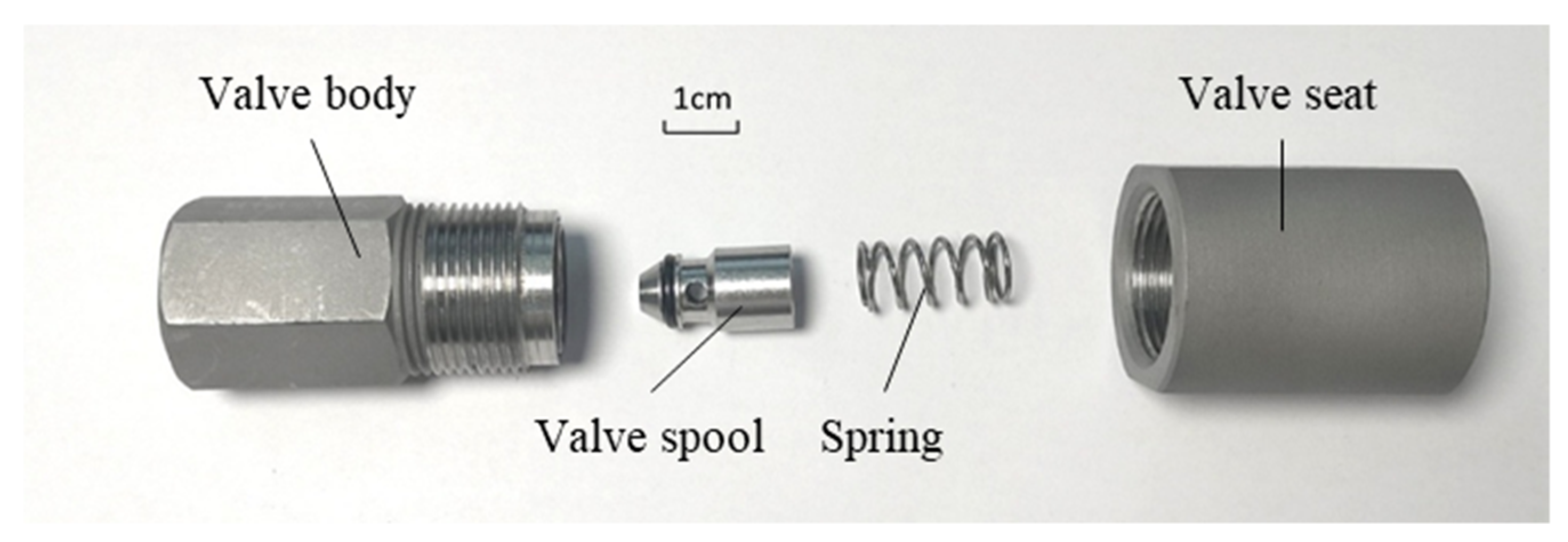
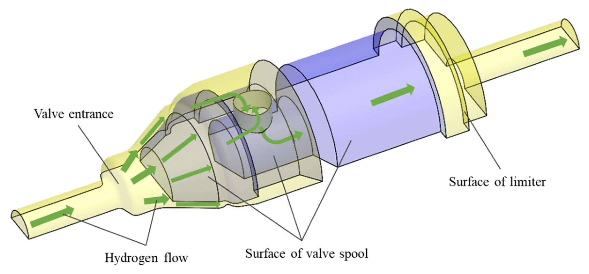
2.1. D Model of the Check Valve

A check valve, which is typically used in hydrogen-refueling stations, was studied in this paper; see Figure 1. It consists of valve body, valve spool, spring, and valve seat. The valve spool is shaped like a truncated cone, and there is an O-ring on the valve spool surface. There is a through-hole in the radial direction of the valve spool, which can change the flow direction, and drive hydrogen flow into the valve spool. The valve spool is hollow inside and is used to set the spring and control the flow channel of the hydrogen gas. A limiter inside the valve seat is designed to limit the displacement of the valve spool.
The mass of the valve spool is 7.2 g and maximum displacement of the valve spool is 2 mm. Both inlet- and outlet- diameters are 3 mm. A 3D model of the check valve is shown in Figure 2. If a high-pressure difference occurs between the front and back of the valve spool, fluid force is generated at the valve spool surface. When the fluid force exceeds the spring force and friction, the valve spool moves. Then, the O-ring seal fails due to clearance, hydrogen passes through the O-ring channel and enters the interior of the valve spool through the hole, reaching the downstream end of the pipeline.

2.2. Governing Equations for Transient Hydrogen Gas Flow

The mass-conservation equation is:
ρ t + x i ( ρ u i ) = 0
where t is time, ρ is gas density, u i is the velocity tensor, and x i denotes the coordinate direction. The subscript i = 1, 2, 3 denotes the x, y, and z directions, respectively.
The law of conservation of the momentum is:
ρ t ( ρ u i ) + x j ( ρ u i u j ) = p x i + x j ( τ i j ρ u i u j ) + ρ F i
where p is the static pressure, ρ is the fluid density, τ i j is the stress tensor, F i is the volume force in the i direction, and ρ u i u j is the Reynold stress.
The conservation of energy equation is:
t ( ρ E ) + x i [ u i ( ρ E + p ) ] = x i ( k e f f T x i j h j j j + u j τ i j ) + S h
where keff is the effective thermal conductivity, jj is the diffusion flux of the component, Sh is the other defined volumetric heat source term.
The energy E of per unit mass fluid is denoted as:
E = h p ρ + u i 2 2
where h is enthalpy of hydrogen gas.
To predict hydrogen flow behavior, the National Institute of Standards and Technology (NIST) real gas model was applied to illustrate the compressibility effect of real high-pressure hydrogen [21]. Based on this method, Zheng proposed a standardized equation for hydrogen gas compressibility factor, which can accurately predict the properties of high-pressure hydrogen gas flow [22]. The NIST real gas model contains many types of pure fluids from the reference fluid properties (REFPROP) database [23]. Real hydrogen can be presented as follows:
ρ = M p Z R T
where ρ is the density, M is the molar mass, 2.016 g/mol, p is the pressure, MPa, T is the absolute temperature, R is the molar gas constant, 8.3145 J/(mol∙K), and the compressibility factor Z can be described as follows:
Z = i = 1 6 j = 1 4 v i j p i 1 ( 100 T ) j 1
where v i j is the coefficients, which can be found in Zheng’s paper [22].

2.3. Movement Equations for the Valve Spool

The movement characteristic of the valve spool is very important for the safety of the check valve. If the spool speed is too high during the opening process, valve body and spool collide with a strong force, which can cause damage to the valve and leakage of hydrogen. According to previous research, the spool movement is due to the combined forces of fluid and spring. Because the gap between the spool wall and the valve body wall is very small, the valve spool only moves in the x direction, and the movement of the valve spool is determined using the six degree of freedom (DOF) model [24], which can be established using a user-defined function (UDF) method. Hence, the valve spool movement equation can be formulated using Newton’s second law as:
m · x + c · x + k · x = F f l o w
where the constant m is the valve spool mass, the constant c is the spring damping coefficient, the constant k is the spring stiffness coefficient, and Fflow is the force applied by flowing fluid. x is the acceleration of the valve spool in the x direction, x is the velocity of the valve spool in the x direction, c · x is the damping force acting on the valve spool in the x direction, and k · x is the spring force acting on the valve spool in the x direction.
For transient flow, the flow is relative to transient time. Therefore, x , x and x in Equation (7) can be written as:
x t + Δ t = F f l o w c · x t k · x t m = x t + Δ t x t Δ t
x t + Δ t = x t + x t + Δ t · Δ t = x t + Δ t x t Δ t
x t + Δ t = x t + x t + Δ t · Δ t
where Δt is the defined time step. By calculating the forces for the previous step, the new position, velocity, and acceleration of the valve spool at the new time-step can be determined.

3. CFD Model and Transient-Flow Model of the Check Valve

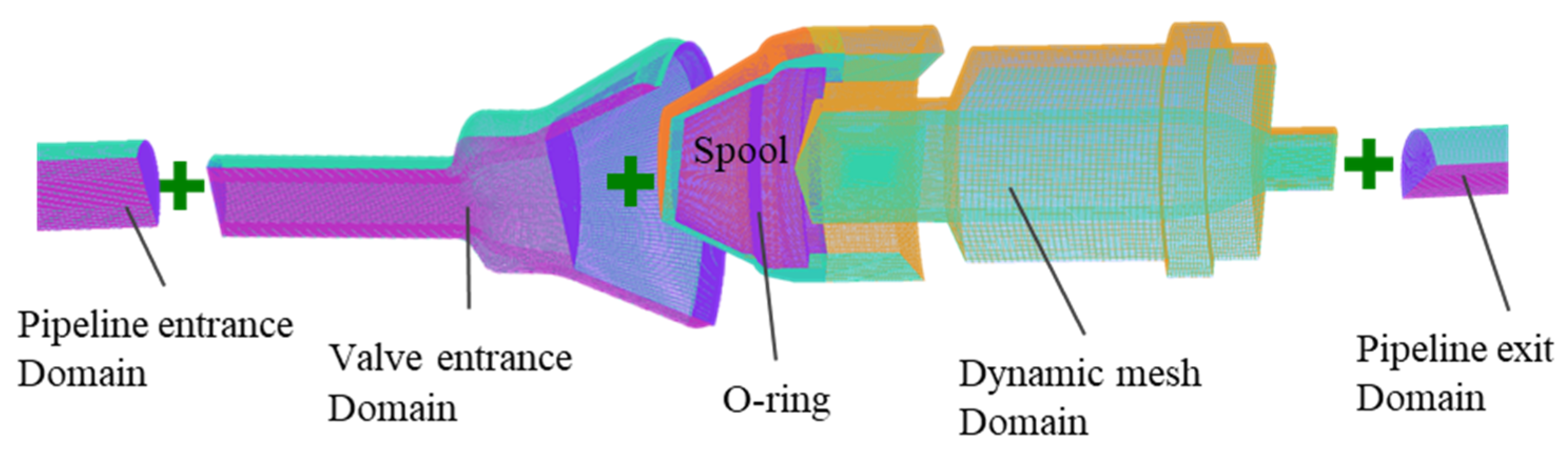
3.1. Domain Decomposition and Dynamic Mesh Generation

A flow channel model for the check valve is shown in Figure 3. To better understand the high-pressure hydrogen-flow performance, both valve inlet and outlet were extended. Because the check valve is axisymmetric, only one half is presented in this study.
To represent the flow characteristic more accurately, the hydrogen gas flow region of the check valve was divided into four domains: pipeline entrance, valve entrance, dynamic mesh, and pipeline exit.
As shown in Figure 4, the structured meshes were constructed using ANSYS-ICEM for the four flow domains. The mesh density of the pipeline entrance domain and pipeline exit domain were relatively coarse, while the mesh density of the valve entrance domain and the dynamic mesh domain were relatively dense. The interface boundaries conditions were applied between the adjacent domains. Moreover, the intermediate section surface was set as the symmetry-plane boundary condition.

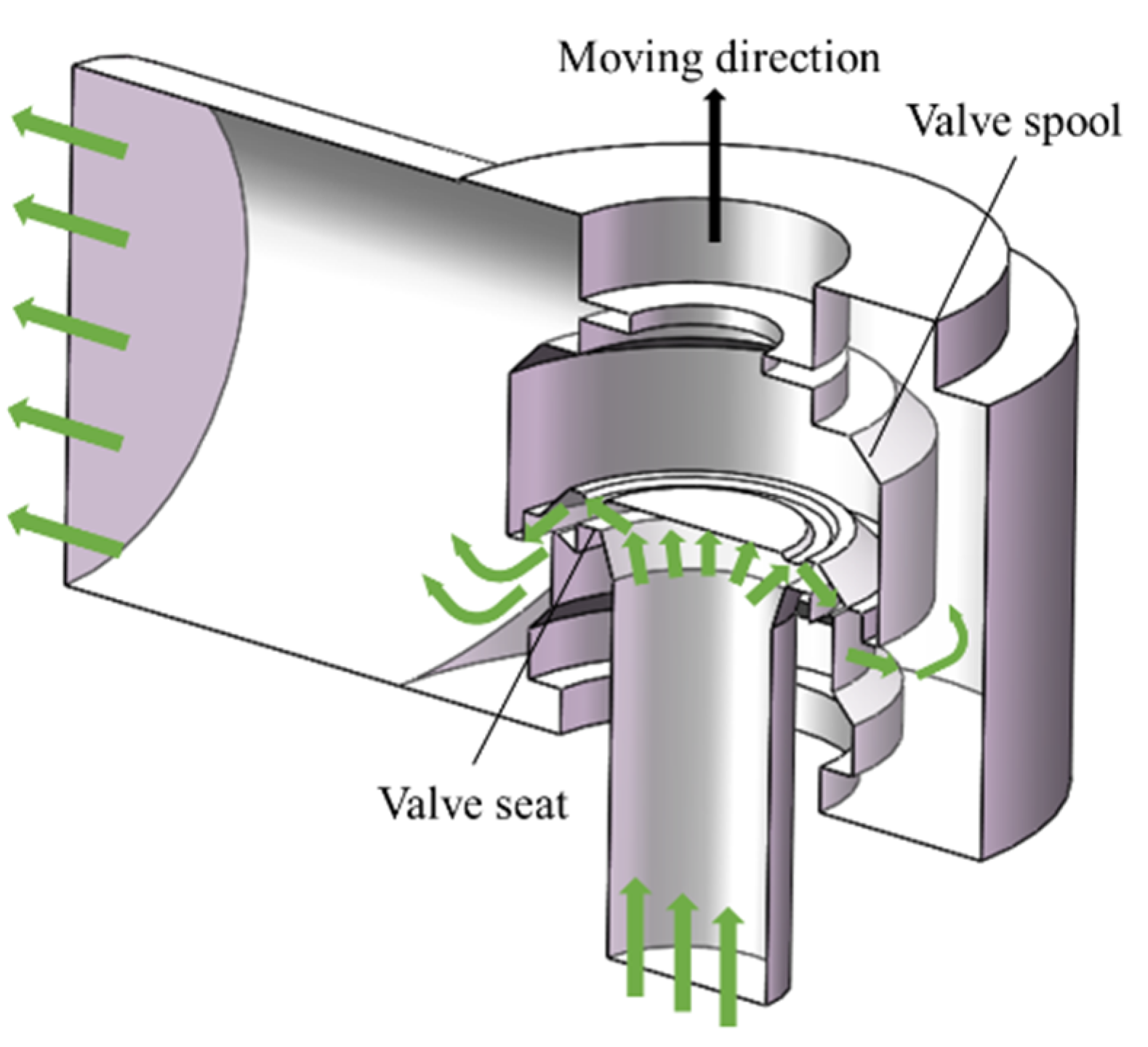
3.2. Moving Mesh Boundary Method of the CFD Model

In this paper, the moving mesh method is applied to predict the flow behaviors of the check valve, which is obtained based on the mesh generation and disappearance technology. Figure 5 shows the moving mesh boundary conditions for the CFD model. The valve spool was regarded as a rigid body that can move freely in the x direction. The interface boundary of the moving grid flow region was set as the static boundary.
In this paper, the ANSYS Fluent software was applied for the simulations. For modeling transient flow, pressure-based solver was adopted, and the energy equation was activated. Viscous effects were considered with the k-ε turbulent model [18]. The pressure-velocity coupling method used the semi-implicit method for pressure linked equations (SIMPLE); the convergence criteria were that all the residuals were approximate 10−5. The six DOF method was used to compute the fluid force on valve spool surface [24]. The layering mesh method was selected to modify the mesh, which can generate a structured mesh and maintain mesh quality during the transient. The valve spool, valve body, and valve seat were considered rigid bodies; only minor deformations were assumed. To maintain continuous flow at the beginning of the spool movement, 0.02 mm initial displacement was provided to establish a continuous flow field for the first calculation step. This method was also used in previous studies [19,20].

3.3. Verification of the Transient CFD Model

This work uses the paper by Song [19] to verify the validity of the transient CFD model. The valve was a safety relief valve, and the principle and structure were similar to that of the check valve. It also consists of valve body, valve spool, and spring. A geometric model of the safety relief valve is shown in Figure 6 [19]. The inlet diameter was 30 mm, and the outlet diameter was 80 mm. The valve spool mass was 0.96 kg, and its diameter was 70 mm. The spring stiffness coefficient was 22.3 kN/m, and the maximum displacement of the valve spool was 8 mm.
Figure 7 shows a comparison of the valve spool displacement for the two methods [20]. It reveals that the displacement curve of the valve spool shows the same characteristic in both methods. The time when the valve spool reached maximum displacement is defined as the maximum opening time of the check valve. The difference between the maximum opening time of the present study (6ms) and Song’s work (5.9 ms) was less than 2%. In addition, during the opening process of the valve, the displacement difference for the two methods was very low, and the trends were almost identical. The above results confirm that the numerical method used in our study is valuable for finding the transient flow characteristic of high-pressure hydrogen check valves.

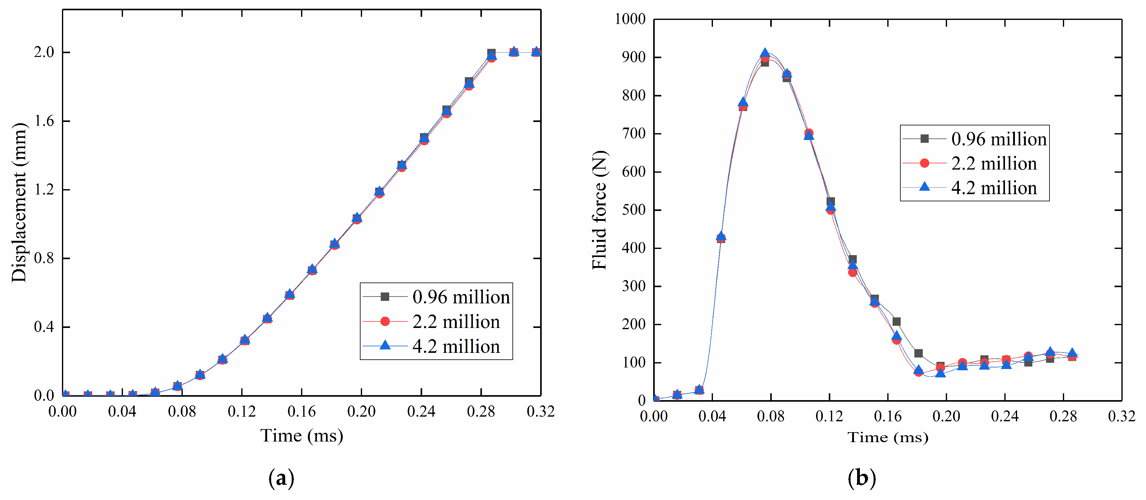
3.4. Effect of the Mesh Density on the Validity of the CFD Results

To investigate the mesh density effect on the flow characteristic, three models with different mesh densities were applied and analyzed this paper. This was implemented by comparing the displacement and force regulation of the valve spool during the opening process. In the three models, the hydrogen pressure at the inlet and outlet were set to 10 MPa and 2 MPa, respectively. The mesh densities were 0.96 million, 2.2 million, and 4.2 million, respectively.
Figure 8a shows the displacement of the valve spool for the three models during the opening process. At the beginning of the process, because the hydrogen flow occurred far away from the valve spool, there was no displacement. After 0.05 ms, the impact of the hydrogen flow started. The high-pressure hydrogen flow generated a maximum fluid force of 900 N in a very short time; see Figure 8b. The huge fluid force pushed the valve spool to the end of the movement (at about 0.3 ms). The three models show a good consistency for the displacement and fluid force characteristics, with a difference of less than 1% between the models. Considering the accuracy, stability, and economical of the simulation, a model with 2.2 million mesh density was selected.
Figure 9a shows the initial meshes of the valve spool and symmetrical plane for the chosen mesh. The surface mesh of the spool was red, the symmetrical plane mesh was gray, and these meshes were very regular. Figure 9b shows the updated meshes of section A-A marked in Figure 9a during the transient. Because of the layering mesh method, the hexahedral structured meshes were generated, the size and shape of the updated meshes were similar to the initial meshes, which ensure that no element with a negative volume or poor quality occurred at any iteration when the spool was moving.

4. Detailed Parameters for the Investigated Cases

This study mainly focuses on the transient flow characteristic during the opening process of the check valve. Taking into account safety factors, the extreme pressure difference between the front and back of the valve was not permitted generally, because it would lead to greater energy loss, and the resulting high impact force would cause serious damage to the pipeline valves and other accessories. Therefore, most of hydrogen refueling stations use multi-stage filling technology, and the filling pressure difference at each stage is relatively low [25,26]. In this paper, effect of the inlet pressure on the transient flow characteristic is studied, and four different pressures were selected as the inlet pressure. The detailed parameters for the different cases are shown in Table 1. The most dangerous operating conditions were a valve inflow pressure of 20 MPa and a valve back pressure of 2 MPa. In all cases, the inlet and outlet boundary conditions were set for pressure inlet and outlet, respectively. Considering the opening process was very rapid, the wall surfaces were assumed as non-slip boundary conditions and adiabatic. In all cases, the outlet pressure of the hydrogen gas Poutlet was set to 2MPa, the spring stiffness coefficient was 1000 N/m, the spring damping coefficient was 2 N/(m/s), and the spring pre-compressed length was 10 mm.

5. Results and Discussions

5.1. Transient-Flow Characteristics of High-Pressure Hydrogen Gas During the Opening Process

Case 3 in Table 1 was calculated to study the flow performance of the check valve. Figure 10 shows the flow contour for the check valve at 0.02 ms, 0.04 ms, 0.08 ms, 0.12 ms, 0.20 ms, and 0.30 ms. Figure 10a shows the pressure distribution on the valve spool surface. Figure 10b shows the section of the flow channel for the valve spool, which provides a better representation of the pressure distribution inside the valve spool. Figure 10c shows the velocity distribution of hydrogen flow at the check valve.
As shown in Figure 10a–c, at 0.02 ms, the high-pressure hydrogen gas does not arrive at the spool position, and the pressure changes little on the surface of the valve spool. At 0.04 ms, the high-pressure hydrogen gas arrives and hits the valve spool surface. The flow velocity increases sharply and the pressure changes rapidly; see Figure 10b,c. At 0.08 ms, the high-pressure hydrogen gas has completely filled the cavity in front of the sealing section, and the pressure at the valve spool surface has also increased. At 0.12 ms, the valve spool has moved by a certain distance driven by the fluid force, which produced enough clearance near the O-ring for hydrogen to flow through quickly. Therefore, the pressure in the connection-cavity decreased compared to the previous time, and the velocity improved in all areas with fluids.
At 0.20 ms, the valve spool has moved a longer distance; therefore, the gap near the O-ring was large enough for the resistance of the flow to be very low. In addition, there was no significant pressure drop in the fluid area. The pressure at the valve spool surface was largely uniform. The velocity at the inlet and outlet pipes was higher than the velocity inside the valve spool. This suggests that the flow area near the valve spool was larger than the flow area at the inlet and outlet pipes. At 0.30 ms, the valve spool reached the maximum displacement.
The movement characteristic of the valve spool was investigated. Figure 11 shows the location of two monitoring points: One is in the cavity region in front of the valve spool and the other at the outlet pipe. Figure 12 shows the pressure variation for the two monitoring points. Before t = 0.03 ms, the pressure remained almost unchanged. After 0.03 ms, because of the arriving high-pressure hydrogen gas, the pressure in this area increased sharply and reached the maximum value at 0.08 ms, which was 12 MPa. Subsequently, the pressure of the point-ahead decreased sharply to 5.6 MPa at 0.18 ms. After that moment, the point-ahead pressure gently increased. The point-behind pressure distribution shows that the pressure in this region resembles more a hysteresis than the point-ahead region. The pressure increase was also consistent with the point-ahead pressure increase. At the end of the opening process, the pressure in this area was about 4 MPa.
Figure 13 shows the relationship between the fluid force and resulting spring force during the opening process. In this paper, the resulting spring force includes the spring force and the damping force. Figure 14 is the acceleration variation for the valve spool during the opening process. As shown in Figure 13; Figure 14, from 0 ms to 0.04 ms, because the valve spool was not affected by the high-pressure hydrogen flow, the pressure, displacement, velocity, and acceleration were almost 0. From 0.04 ms to 0.08 ms, due to the impact of the high-pressure hydrogen flow and the small opening gap of the valve spool, the pressure in the connection-cavity increased rapidly, the fluid force at the valve spool surface increased rapidly to 900 N, and the valve spool acceleration also sharply increased to a very high value (1.2 × 10⁵ m/s2).
From 0.08 ms to 0.18 ms, as the valve spool gradually opened, the flow area near the O-ring became larger, and the hydrogen in front of the sealing section could bypass the O-ring and enter the valve spool. Therefore, the pressure in the cavity was reduced, the fluid force on valve spool surface was reduced to 74 N, and the valve spool acceleration decreased to 6000 m/s2.
Between 0.18 ms and 0.3 ms, when the valve spool had just contacted the limiter, as the pressure in the cavity increased, the fluid force on the spool surface and the acceleration of the valve spool showed a slow increase. This is consistent with the results shown in Figure 10 and Figure 12.
The trends of the fluid force curve and the acceleration curve were almost the same. This is because the acceleration was determined by the three forces: the fluid force, the spring force, and the damping force. The maximum fluid force due to high-pressure hydrogen flow exceeded 900 N, which was much higher than for the resulting spring force. This means the fluid force of hydrogen gas dominates, and the fluid force curve and acceleration curve show a similar characteristic.
Figure 15 shows the relationship between displacement and velocity of the valve spool and the opening time. At the beginning, when the high-pressure flow has little effect on the valve spool, the valve spool remained still. After 0.04 ms, the high-pressure flow started, the flow force and the acceleration of the valve spool increased sharply, the velocity of the valve spool increased very quickly, and the displacement increased too. At 0.18 ms, the velocity of the valve spool turn increased quickly into increased gently; this is because the acceleration is reduced to a minimum. Subsequently, a variation of the velocity and the displacement of the valve spool was consistent with the acceleration characteristic. When the valve spool arrived at the limiter, the velocity of the spool was about 10.9 m/s. The displacement vs. time curve in Figure 15 is similar to the work by Song [19] in Figure 7; the difference is the maximum opening time. This is because the pressure is higher, and the spool is lighter in the present work.
At the end of the opening process, the flow force on the spool was about 116 N, and the velocity of the spool was 10.9 m/s. This indicates that the spool hit the limiter with a 116 N force at 10.9 m/s. Given that the check valve is very small, it can generate a serious impact on the valve structure, and may damage the seal surface of the check valve. This study also discusses a potential application for estimation of the strength and safety of check valves.

5.2. Effect of Inlet Pressure on the Movement Characteristic of the Valve Spool

The high-pressure hydrogen gas generated the fluid force on the valve spool, which produced a very strong impact on both valve spool and valve structure. Therefore, to investigate the pressure effect on the characteristic of the opening process, four different inlet pressures at hydrogen stations were used: 5 MPa, 7 MPa, 10 MPa, and 20 MPa. The parameter details are shown in Table 1 for cases 1–4.
Figure 16 shows the relationship between the lift of the valve spool and the opening time of the check valve at different inlet pressures. Before t = 0.05 ms, due to the impact shock (because high-pressure hydrogen flow did not occur at the valve spool), the displacement of the valve spool was 0. As the impact from high-pressure hydrogen flow began to happen, the displacement of the valve spool increased quickly. In case 1 Pinlet = 5MPa, the maximum opening time was 0.5 ms. When the driving pressures were 7 MPa, 10 MPa, and 20 MPa, the maximum opening times were 0.37 ms, 0.28 ms, and 0.25 ms, respectively. As the inlet pressure of the hydrogen gas increased, the maximum opening time of the check valve was shorter. This happened because the higher pressure generated a higher fluid force and acceleration, which caused the valve spool to move faster.
Based on the analysis above, the force from the high-pressure hydrogen gas was much higher than that for the spring, and the acceleration of the valve spool was also mainly due to the fluid force. Therefore, the fluid force of the valve spool at different inlet pressure conditions was investigated. Figure 17 shows the variation of the fluid force and the acceleration of the valve spool at different inlet pressures vs. time. As shown in Figure 17a, all curves show that the force increased sharply until it reached a maximum value. Then it decreased quickly. It also shows that the maximum fluid force of the four cases occurred at the same times t = 0.8 ms. The result indicates that the time of the maximum fluid force is independent of the inlet pressure.
Before the valve spool reached the maximum displacement, the fluid force of the valve spool reached equilibrium. Moreover, the high fluid force generated a high acceleration of the valve spool; see Figure 17b. For Pinlet = 5 MPa, the maximum fluid force on the valve spool was about 380 N, and the maximum acceleration was about 5 × 10⁴ m/s2. When Pinlet = 20 MPa, the maximum fluid force at the valve spool exceeded 1060 N, and the maximum acceleration was about 1.4 × 10⁵ m/s2. This shows that, as the inlet pressure of the hydrogen gas flow increased, the maximum fluid force and the acceleration of the valve spool increased too. The main reason for this is that as the inlet pressure of the gas flow increased, the pressure difference between the spool front and spool back increased. Therefore, the higher pressure difference generated a stronger fluid force at the valve spool, the acceleration was higher, and the time to reach the valve limiter was shorter.
In addition, the average fluid force was different for different inlet pressure conditions. When the valve spool reached the limiter, the fluid force of the four cases was 49.2 N, 82.4 N, 116 N, and 155.4 N, respectively.
Figure 18 shows the change of valve spool velocity with the displacement during the opening process. When the impact of the high-pressure hydrogen flow occurred, the velocity of the valve spool increased rapidly. During the opening process, when the valve spool reached the limiter, the velocity of the valve spool reached its maximum. As shown in Figure 18, for Pinlet = 5 MPa, 7 Mpa, 10 Mpa, and 20 MPa, the maximum valued of the valve spool velocity were 5.9 m/s, 8.2 m/s, 10.9 m/s, and 13.6 m/s, respectively. This shows that inlet pressure of the hydrogen gas clearly affected the velocity of the valve spool. As the inlet pressure of the hydrogen flow increased, the maximum velocity of the valve spool increased too. Considering the fluid force was also very high, the crash between the valve spool and the limiter was substantial. The results of our studies can help develop safer designs and more reliable application of check valves in the future.

6. Conclusions

A transient CFD model was constructed using the moving mesh method and the NIST real gas model. The model was verified to be valuable in comparison with the previous result. With the new model, the flow characteristic of the check valve during the opening process in high-pressure hydrogen system was studied, and the effect of the parameters on the performance of the check valve was investigated. The main conclusions of this study are:
(1)
The time for the valve spool to reach maximum displacement was very short during the opening process, at about minor second (ms) level. The high-pressure hydrogen gas quickly generates a maximum pressure at the valve spool, as well as a maximum acceleration of 105 m/s2 level. The maximum hydrogen fluid force was about 103 N level, and the resistance force from the spring was negligible compared to the fluid force.
(2)
The inlet hydrogen pressure had a very significant effect on the opening behavior of the valve spool. When the inlet pressure increased, the fluid force increased, the acceleration of the valve spool also increased; the time needed for the valve spool to reach the limiter decreased; and the velocity of the valve spool increased; whereas the time of the maximum fluid force was constant. Obviously, the higher inlet pressure generated a higher impact between the valve spool and the valve limiter.
The quantitative results of this study can provide an improved design and possibly new applications for check valves. For example, according to specific working conditions, the designer can optimize the structure and suitable material of the check valve, improving the ability of the impact resistance between valve spool and valve limiter. As high-pressure hydrogen refueling stations and systems become increasingly popular, our group will continue to study the performance of check valves.

Author Contributions

Conceptualization, J.Z.; methodology, S.S. and X.J.; software, J.Y. (Jiangcun Yu) and J.C.; validation, J.C.; formal analysis, S.S.; investigation, Z.Z. and J.Y. (Jiangcun Yu); data curation, J.Y. (Jianjun Ye); writing—original draft, J.Y. (Jianjun Ye) and Z.Z.; writing—review & editing, J.Z.; visualization, X.J.; supervision, J.Z.; project administration, J.Y. (Jianjun Ye); funding acquisition, J.Z. All authors have read and agreed to the published version of the manuscript.

Funding

This project was supported by the National Key R&D Program of China (Grant No. 2019YFB1505300), National Natural Science Foundation of China (Grant No. 51976067), and the Open Project of Foshan Xianhu Laboratory of the Advanced Energy Science and Technology Guangdong Laboratory (Grant No. XHD2020-004).

Conflicts of Interest

The authors declare no conflict of interest.

References

  1. Liu, Z.; Kendall, K.; Yan, X. China progress on renewable energy vehicles: Fuel cells, Hydrogen and Battery hybrid vehicles. Energies 2019, 12, 54. [Google Scholar] [CrossRef] [Green Version]
  2. Kharel, S.; Shabani, B. Hydrogen as a Long-term Large-scale energy storage solution to support renewables. Energies 2018, 11, 2825. [Google Scholar] [CrossRef] [Green Version]
  3. Abdalla, A.M.; Hossain, S.; Nisfindy, O.B.; Azad, A.T.; Dawood, M.; Azad, A.K. Hydrogen production, storage, transportation and key challenges with applications: A review. Energy Convers. Manag. 2018, 165, 602–627. [Google Scholar] [CrossRef]
  4. Moradi, R.; Groth, K.M. Hydrogen storage and delivery: Review of the state of the art technologies and risk and reliability analysis. Int. J. Hydrogen Energy 2019, 44, 12254–12269. [Google Scholar] [CrossRef]
  5. Cerniauskas, S.; Grube, T.; Praktiknjo, A.; Stolten, D.; Robinius, M. Future Hydrogen Markets for Transportation and Industry: The Impact of CO2 Taxes. Energies 2019, 12, 4707. [Google Scholar] [CrossRef] [Green Version]
  6. Zheng, J.; Liu, X.; Xu, P.; Liu, P.; Zhao, Y.; Yang, J. Development of high pressure gaseous hydrogen storage technologies. Int. J. Hydrogen Energy 2012, 37, 1048–1057. [Google Scholar] [CrossRef]
  7. Kim, Y.; Shin, D.; Kim, C. On-Board Cold Thermal Energy Storage System for Hydrogen Fueling Process. Energies 2019, 12, 561. [Google Scholar] [CrossRef] [Green Version]
  8. Apostolou, D.; Xydis, G. A literature review on hydrogen refuelling stations and infrastructure. Current status and future prospects. Renew. Sustain. Energy Rev. 2019, 113, 109292. [Google Scholar] [CrossRef]
  9. Muratori, M.; Bush, B.; Hunter, C.; Melaina, M. Modeling Hydrogen Refueling Infrastructure to Support Passenger Vehicles. Energies 2018, 11, 1171. [Google Scholar] [CrossRef] [Green Version]
  10. Lowesmith, B.J.; Hankinson, G.; Chynoweth, S. Safety issues of the liquefaction, storage and transportation of liquid hydrogen: An analysis of incidents and HAZIDS. Int. J. Hydrogen Energy 2014, 39, 20516–20521. [Google Scholar] [CrossRef]
  11. Pagliaro, M.; Iulianelli, A. Hydrogen Refueling Stations: Safety and Sustainability. Gen. Chem. 2019, 6, 190029. [Google Scholar] [CrossRef]
  12. Sakamoto, J.; Sato, R.; Nakayama, J.; Kasai, N.; Shibutani, T.; Miyake, A. Leakage-type-based analysis of accidents involving hydrogen fueling stations in Japan and USA. Int. J. Hydrogen Energy 2016, 41, 21564–21570. [Google Scholar] [CrossRef] [Green Version]
  13. Yu, J.; Yu, S. Numerical and experimental research of flow and sound fields in an axial-flow check valve and its optimization. Adv. Mech. Eng. 2015, 7, 2071731070. [Google Scholar] [CrossRef] [Green Version]
  14. Darby, R.; Aldeeb, A.A. The dynamic response of pressure relief valves in vapor or gas service. Part III: Model validation. J. Loss Prev. Process Ind. 2014, 31, 133–141. [Google Scholar] [CrossRef]
  15. Filo, G.; Lisowski, E.; Rajda, J. Flow analysis of a switching valve with innovative poppet head geometry by means of CFD method. Flow Meas. Instrum. 2019, 70, 101643. [Google Scholar] [CrossRef]
  16. Zhang, Z.; Jia, L.; Yang, L. Numerical simulation study on the opening process of the atmospheric relief valve. Nucl. Eng. Des. 2019, 351, 106–115. [Google Scholar] [CrossRef]
  17. Sibilla, S.; Gallati, M. Hydrodynamic Characterization of a Nozzle Check Valve by Numerical Simulation. J. Fluids Eng. 2008, 130, 121101. [Google Scholar] [CrossRef]
  18. Saha, B.K.; Chattopadhyay, H.; Mandal, P.B.; Gangopadhyay, T. Dynamic simulation of a pressure regulating and shut-off valve. Comput. Fluids 2014, 101, 233–240. [Google Scholar] [CrossRef]
  19. Song, X.; Cui, L.; Cao, M.; Cao, W.; Park, Y.; Dempster, W.M. A CFD analysis of the dynamics of a direct-operated safety relief valve mounted on a pressure vessel. Energy Convers. Manag. 2014, 81, 407–419. [Google Scholar] [CrossRef] [Green Version]
  20. Song, X.G.; Wang, L.T.; Park, Y.C.; Sun, W. A Fluid-structure Interaction Analysis of the Spring-Loaded Pressure Safety Valve during Popping Off. Proced. Eng. 2015, 130, 87–94. [Google Scholar] [CrossRef] [Green Version]
  21. Mamedov, B.A.; Somuncu, E.; Askerov, I.M. Evaluation of Speed of Sound and Specific Heat Capacities of Real Gases. J. Thermophys. Heat Transf. 2018, 32, 984–998. [Google Scholar] [CrossRef]
  22. Zheng, J.; Zhang, X.; Xu, P.; Gu, C.; Wu, B.; Hou, Y. Standardized equation for hydrogen gas compressibility factor for fuel consumption applications. Int. J. Hydrogen Energy 2016, 41, 6610–6617. [Google Scholar] [CrossRef]
  23. Johnson, T.; Bozinoski, R.; Ye, J.; Sartor, G.; Zheng, J.; Yang, J. Thermal model development and validation for rapid filling of high pressure hydrogen tanks. Int. J. Hydrogen Energy 2015, 40, 9803–9814. [Google Scholar] [CrossRef] [Green Version]
  24. Nguyen, V.; Vu, D.; Park, W.; Jung, C. Navier-Stokes solver for water entry bodies with moving Chimera grid method in 6DOF motions. Comput. Fluids 2016, 140, 19–38. [Google Scholar] [CrossRef]
  25. Zheng, J.; Ye, J.; Yang, J.; Tang, P.; Zhao, L.; Kern, M. An optimized control method for a high utilization ratio and fast filling speed in hydrogen refueling stations. Int. J. Hydrogen Energy 2010, 35, 3011–3017. [Google Scholar] [CrossRef]
  26. Guo, J.; Xing, L.; Hua, Z.; Gu, C.; Zheng, J. Optimization of compressed hydrogen gas cycling test system based on multi-stage storage and self-pressurized method. Int. J. Hydrogen Energy 2016, 41, 16306–16315. [Google Scholar] [CrossRef]
Figure 1. The components of the check valve.
Energies 13 04222 g001
Figure 2. 3D model of a check valve.
Energies 13 04222 g002
Figure 3. Flow-channel model of the check valve.
Energies 13 04222 g003
Figure 4. Structural grids of the four flow domains.
Energies 13 04222 g004
Figure 5. Moving mesh boundary.
Energies 13 04222 g005
Figure 6. Structure of the safety relief valve.
Energies 13 04222 g006
Figure 7. Displacement during the opening process with the two methods.
Energies 13 04222 g007
Figure 8. Mesh independence test: (a) Displacement of the valve spool in the three models; (b) Fluid force characteristic of the three models.
Energies 13 04222 g008
Figure 9. Initial and updated meshes for the chosen mesh: (a) Initial meshes of the valve spool and symmetrical plane; (b) Updated meshes of section A-A during the transient.
Energies 13 04222 g009
Figure 10. Static pressure and velocity distributions at different moments: (a) Static pressure contours for the symmetrical plane and valve spool surfaces; (b) Static pressure contours for the symmetrical plane; (c) Velocity contours for the symmetrical plane.
Energies 13 04222 g010
Figure 11. Location of two monitoring points and the connection cavity.
Energies 13 04222 g011
Figure 12. The pressure at two monitoring points during the opening process.
Energies 13 04222 g012
Figure 13. Fluid force and resulting spring force during the opening process.
Energies 13 04222 g013
Figure 14. Valve spool acceleration during the opening process.
Energies 13 04222 g014
Figure 15. Displacement and velocity of the valve spool.
Energies 13 04222 g015
Figure 16. Displacement of valve spool for different driving pressures.
Energies 13 04222 g016
Figure 17. Fluid force and acceleration of the valve spool for different inlet pressures: (a) Fluid force for the valve spool vs. time; (b) Acceleration of the valve spool vs. time.
Energies 13 04222 g017
Figure 18. Velocity of the valve spool for different inlet pressures.
Energies 13 04222 g018
Table 1. Parameter details of the cases.
CaseInlet Pressure Pinlet (MPa)Outlet Pressure Poutlet (MPa)Spring Stiffness Coefficient (N/m)
1521000
2721000
31021000
42021000

