Article

Investigating the Width of Isolated Coal Pillars in Deep Hard-Strata Mines for Prevention of Mine Seismicity and Rockburst

1
School of Civil and Resources Engineering, University of Science and Technology Beijing, Beijing 100083, China
2
Shandong Energy Group Company Limited, Jinan 250014, China
3
Hebei State Key Laboratory of Mine Disaster Prevention, North China Institute of Science and Technology, Beijing 101601, China
*
Author to whom correspondence should be addressed.
Energies 2020, 13(17), 4293; https://doi.org/10.3390/en13174293
Submission received: 21 July 2020 / Revised: 2 August 2020 / Accepted: 14 August 2020 / Published: 19 August 2020

Abstract

:
In deep mines, a reasonable design of the widths of isolated coal pillars (ICPs) is critically important, particularly for hard-strata mines. This is because the frequent occurrence of mine seismicity (MS) and rockburst in deep mines often arises from the inappropriate widths of the remnant ICPs. To address this problem, this paper takes the ICP of Yingpanhao Coal Mine in Inner Mongolia in China as the engineering case study and then presents a mechanical model to illuminate the occurrence mechanism of MS induced by the mining on both sides of ICPs. The results indicate that, after the mining on both sides of ICPs, the ICPs will produce a vertical compressive deformation, and the overlying high main key stratum (MKS) will experience a flexure deformation. When the limited deflection of MKS is less than the compression of ICPs, the MKS will be fractured, and the released energy may lead to MS. Based on the mechanism model, a design criterion is proposed for ICP widths; this criterion can effectively reduce the risk of the induced rockburst and MS. Then the occurrence mechanism of MS and the design basis for ICP width are verified by numerical simulation and field microseismic monitoring. The results in this paper may be used as a theoretical guidance for rational ICP design in deep mines and may help mitigate the risk of rockburst and MS from early mining stages.

1. Introduction

With the continuous reduction of shallow coal resources, a large number of mines have gradually commenced deep mining. He et al. [1] simulated the stress change and obtained insight into the pillar burst phenomenon under laboratory conditions, and they pointed out that the pillar burst was one type of rockburst that occurs in underground mines. Lu et al. [2] investigated the microseismic multiparameter characteristics of rockburst hazard induced by hard roof fall and high stress concentration, and they believed that abnormal clusters of sources and high-energy events congregate before rockburst. Konicek et al. [3] measured the stress at different mining stages by compact conical-ended borehole monitoring (CCBM), indicating the energy-storing characteristic (prone to burst/bump) of the coal seam. He et al. [4] investigated the mechanisms and prevention of rockburst and proposed that the steeply inclined and extremely thick coal seams under the condition of gob filling frequently suffer from the occurrence of rockbursts. Wang et al. [5] discovered that a special thick coal seam with complex construction easily led to rockburst during mining. Li et al. [6] found that rockburst was one of the dynamic disasters that can occur during coal mining, noting that it generally resulted in disastrous consequences and posed serious threats to mine health and safety. Bräuner [7] studied the rockbursts in coal mines and their prevention and proposed the conditions of occurrence. He et al. [8] discovered that when gob-side entry retaining was used in thick coal seams, the conventional entry retaining method requires a huge amount of filling materials and may cause entry accidents. The studies mentioned above prove that the mine dynamic disasters caused by the movement and breaks of overlying strata, such as mine seismicity and rockburst, have occurred more frequently and intensively, which has become a problem in China that desperately needs to be solved. At present, isolated coal pillars (ICPs) with different widths are preferred in the mining design with the purpose of avoiding mutual mining disturbances between neighboring mines [9,10], as shown in Figure 1. However, widths that are too small easily induce dynamic disasters, such as rockburst, while widths that are too large are likely to result in a waste of coal resources.
Cao et al. [11] investigated the use of microseismic multidimensional information for the identification of rockbursts in a high-rockburst-risk mining area near a large residual coal pillar. Liu et al. [12] established that skip-mining and the corner coal pillar will lead to the formation of an island longwall coal face, which will induce rockbursts. Li et al. [13] took Longyun Coal Mine’s rockburst accident as an engineering case study to reveal the impact mechanism of the drainage lane of large coal pillars near deep wells. By citing the case of rockburst accidents, Zhu et al. [14] studied the abutment pressure distribution in coal mines with extremely thick alluvium stratum. Therefore, a number of rockbursts have taken place resulting from the unreasonable width design of isolated coal pillar in deep mines. For instance, a 80 m coal pillar in the 1300 and 1301 longwall working faces (LW1300 and LW1301) was left in Yuncheng Coal Mine in Shandong, but rockbursts frequently appeared during the mining of LW1300, which finally greatly damaged the roadway, seen in Figure 2 [13,14]. For those deep mines under the condition of thick hard strata, large-area suspended roofs easily come into being on the overlying hard rock stratum under the support of ICPs. Once the fracture occurs, it is prone to induce underground rockbursts, mine seismicity (MS), and other dynamic disasters, and it also affects the safety and stability of ground pipelines and buildings [7,11,15,16,17,18]. Therefore, it is of great importance to investigate the reasonable width of ICPs based on the collaborative control of MS and rockbursts.
Scholars have carried out many studies on rockbursts and MS caused by the movement of the overlying rock strata and made great achievements. Qian et al. [19] first put forward the key strata theory, providing a theoretical basis for studying the movement of the overlying hard rock stratum above a coal pillar. Pan [20] and Zhang et al. [21] presented the concept of disturbance quantity in the deformation system of coal and rock mass, analyzing the instability mechanism and conditions disturbed by the rockbursts. Jiang et al. [22,23] proposed the theory of the spatial structure of overlying strata and the loaded three-zone structure model, and they then revealed the relationship between the movement of overlying hard rock strata and the rockbursts on an underground stope. Hosseini [24] studied the potential of rockburst in a longwall coal mine by the use of passive seismic velocity tomography and the image subtraction technique, which could effectively identify rockburst-prone areas during mining operation. Cao et al. [11,25,26] investigated the spatial structure of overlying thick hard strata on the isolated working face and the impact of breaking movement on mine seismicity, and they adopted the passive computed tomography detection technology to dynamically evaluate the distribution and evolution process of anomaly region division with strong mine seismicity during a mining process involving isolated coal pillars. Li et al. [6,27] centered on the breaking movement of overlying strata and the characteristics of MS disturbances in top-caving mining and developed targeted prevention solutions. Zhang et al. [28] investigated the compatible deformation model of the superthick rock–coal pillar system and its stability, and they discussed its influence on the occurrence of underground dynamic disasters. Zhu et al. [29] explored the mechanism of overall-instability-induced (OII) rockbursts of ICPs and finally came up with the rockburst risk assessment method.
Nevertheless, the above research results place emphasis on the influence of the movement of overlying strata on MS and rockbursts, the instability-induced rockbursts under the disturbing influence of coal pillars, and the mechanism of overall-instability-induced (OII) rockbursts of ICPs, but few studies have tried to acquire insights into the mechanism of MS under the condition that ICPs are left between the mines or mining areas. In this context, theoretical analysis, microseismic monitoring, and numerical simulation are employed in this paper in an attempt to explore the occurrence mechanism of MS on both sides of an ICP. Based on the overlying strata movement and the mechanism of OII rockbursts, the effect of ICP width on OII rockbursts and MS is discussed, aiming to provide a theoretical basis for the design of ICPs with similar conditions in different mines.

2. Case Study of Mining-Induced Seismicity on Both Sides of an ICP

2.1. Field Conditions of Yingpanhao Coal Mine in Inner Mongolia

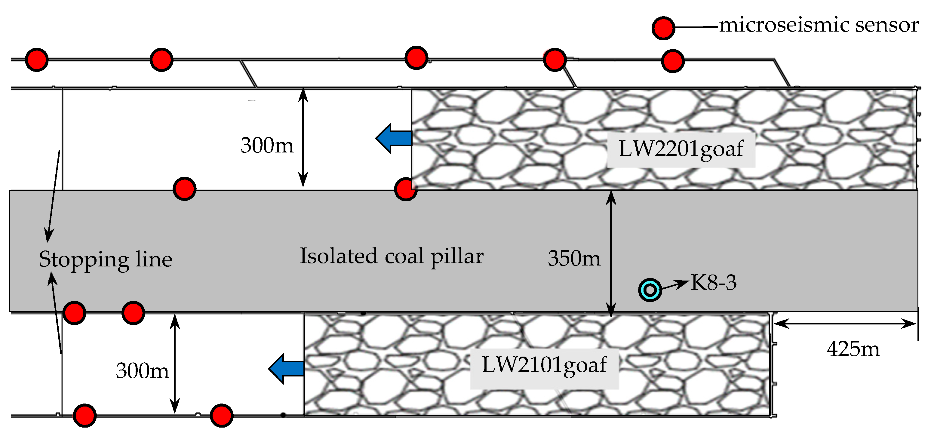
Yingpanhao Coal Mine in Inner Mongolia is a newly built mine. The mine initially plans to mine the #2 coal seam with an average depth of 720 m, near the horizontal coal seam. The coal thickness varies from 5.64 to 7.03 m, with an average thickness of 6.40 m. The uniaxial compressive strength (UCS) is 21 MPa. At the initial stage of mine construction, the 21 and 22 mining areas are planned to be mined. In order to avoid mutual mining disturbance between the two mining areas and reduce the rockburst risk on the working face, a 350 m wide ICP is left between the 21 and 22 mining areas. The north side of the ICP is the 2201 longwall working face (LW2201), the first mining face of the 22 mining area; the south side is the 2101 longwall working face (LW2101), the first mining face of the 21 mining area. LW2201, with a length of 2502 m and a width of 300 m, began to be mined on 3 March 2017; LW2101, with a length of 2077 m and a width of 300 m, began to be mined on 1 December 2017. A 425 m offset was initially kept for the two faces; for both faces, the fully mechanized coal mining method was adopted and full-seam mining was achieved. To reduce the rockburst risk on the working face, large-diameter pressure-relief boreholes with a 150 mm diameter, a 1 m spacing, and a 20 m hole depth were applied to the sides of roadway. By 7 October 2018, the average footage of LW2201 was 1518 m, and that of LW2101 was 1449 m. The layout of the two working faces is shown in Figure 3. This mine adopted an SOS microseismic monitoring system, which was developed in Poland and has been widely applied in coal mines in China [30].
Table 1 shows the structural characteristics of rock strata above the 2-2 coal seam obtained from the K8-3 comprehensive histogram near the coal pillar on the LW2201. It can be seen that the 19.47 m medium-grained sandstone and the 14.79 m siltstone above the coal seam constitute the basic roof; the low inferior key stratum consists of the sandstone group with a 42 m distance from coal seam and a 38.55 m thickness; and a 324.45 m superthick red sandstone group, nearly 300 m distant from the coal seam, is the main key stratum (MKS) for controlling the roof movement.

2.2. Description of Mine Seismicity on the Working Face

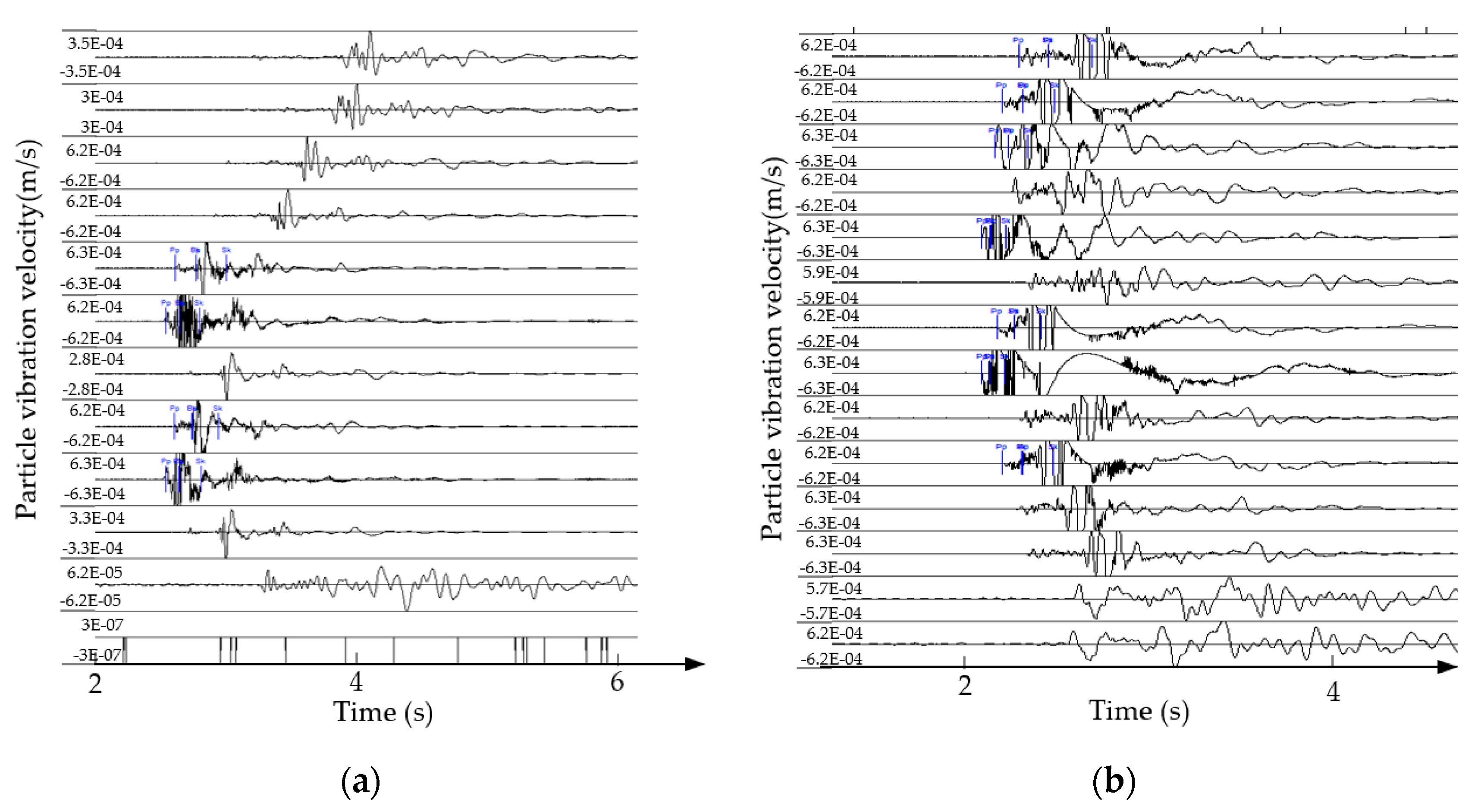
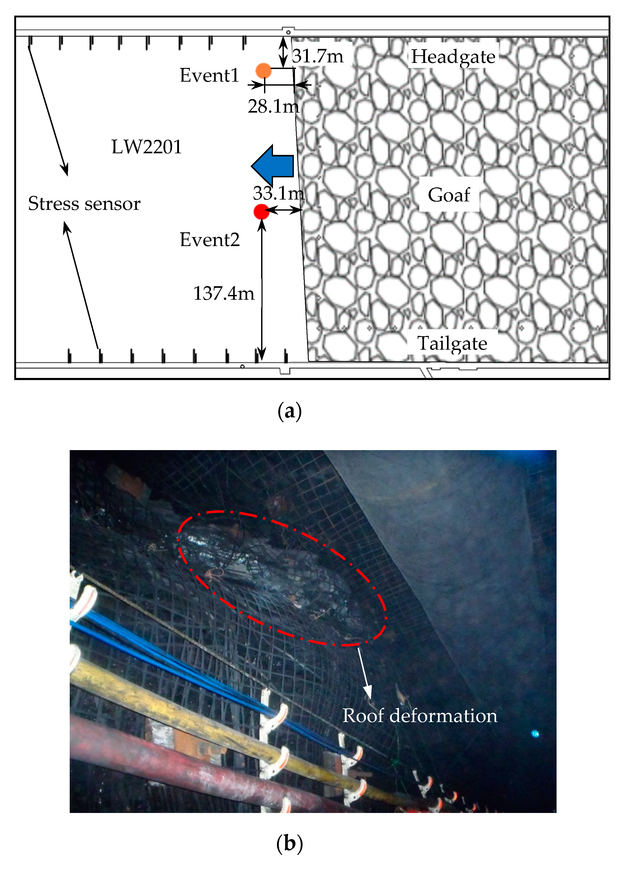
On 7 October 2018, two MS events occurred on the LW2201 during the mining process, and the observed waveforms are displayed in Figure 4. In the figure, Pp and Pk are the arrival time and end time of the P-wave, respectively, while Sp and Sk are the arrival time and end time of the S-wave, respectively. According to the arrival time and particle vibration velocity in the waveforms, the SOS microseismic monitoring system analysis showed that the 17:49 MS event, 28.1 m from the working face, 31.7 m from the headgate, and 296.06 m above the coal floor, produced 5.08 × 10⁵ J of energy with a magnitude of 2.06. The 18:11 MS event was 33.1 m from the working face, 137.4 m from the tailgate, and 298.87 m above the coal floor, releasing 1.16 × 10⁶ J of energy and reaching a magnitude of 2.25. The plane projection drawing of the events is displayed in Figure 5a. The time interval between the two events was 21 min. After the incident, a strong seismic sensation was experienced on the ground; a large coal cannon sound was heard on the working surface; obvious and slight shakes could be noticed at the end and the head of the coal cutting machine, respectively; a large amount of slag dropped from the roof within 200 m in front of the working face’ and roof deformation could be found in some zones of the 200-m roadways, as shown in Figure 5b. The online stress monitoring indicated that there was no significant change in the stress of the two gate roads before and after the incident.
The breaking of different rock strata induces MS events with different energy levels [25,31]. The analysis of the rock strata structure above the 2-2 coal seam and the microseismic source fracture height demonstrated that the 106 J event could take place only when the overlying high-positioned thick hard rock stratum was broken. Preliminary analysis suggested that MS was induced by the breaking of the MKS (red layer) above the coal seam, while the breaking resulted from the mutual influence after the mining on both sides of the ICP.

3. Occurrence Mechanism of MS on Both Sides of an ICP

To avoid the mutual mining disturbance, mitigate the surface deformation, and control mine disasters, mines are usually provided with ICPs [9,10,32]. With the continuous mining on both sides of an ICP, the overlying strata of the goafs will collapse, crack, bend, and sink from bottom to top, layer by layer. The overlying high MKS above ICP will be subjected to the gravity-induced deflection, which will be transmitted to the ICP via the lower rock strata, while the ICP can give a reactive force to keep the strata stable. Meanwhile, the ICP generates a compressive deformation in the vertical direction due to the support pressure transferred from the goafs on both sides and the stress above the coal pillar. Therefore, the relationship between the limited deflection of the overlying high MKS and the vertical compression amount of the coal pillar needs to be analyzed in detail.

3.1. Flexural Deformation of the MKS

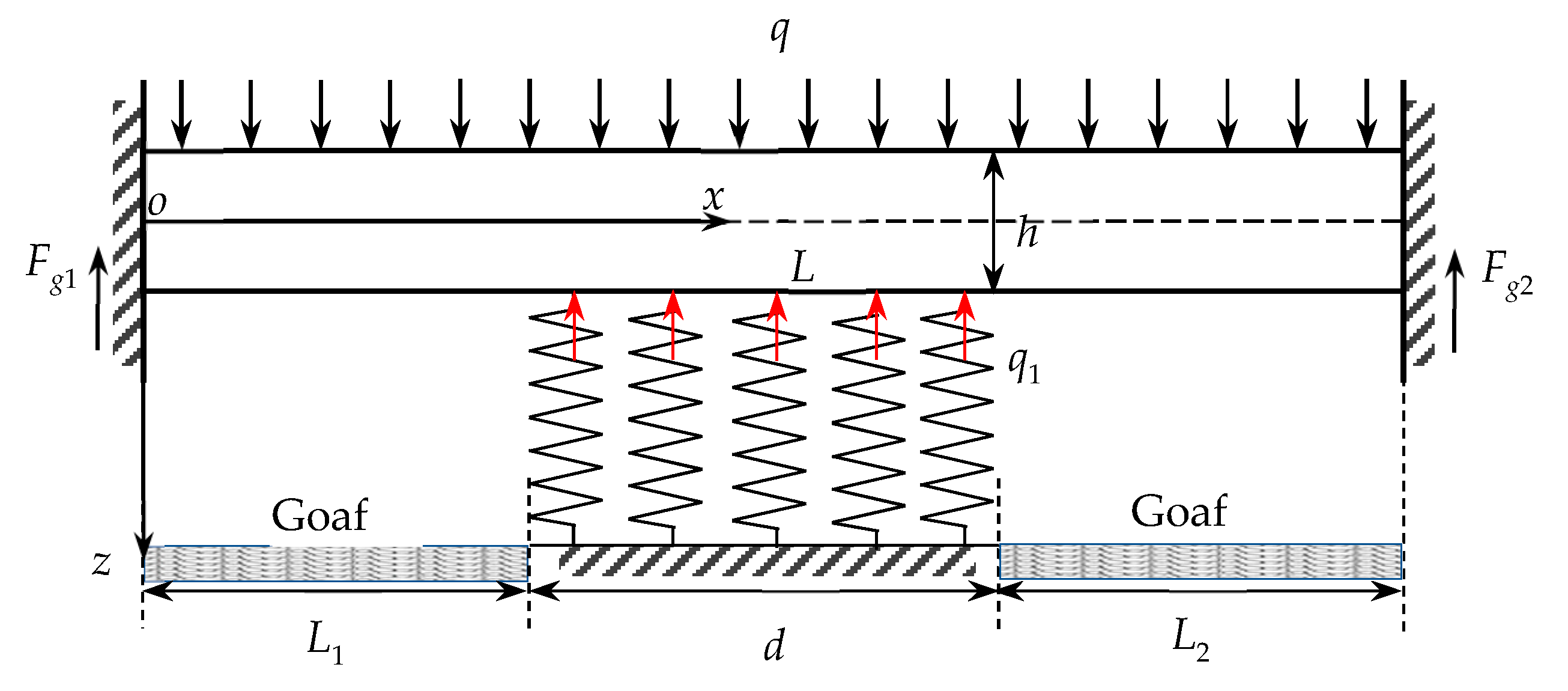
During the coal seam mining process, the span of MKS will not expand indefinitely. If the span of the MKS is smaller than the width of the ICP, it cannot remain self-stabilized after mining and is likely to break. Thus, the following just takes the case where the span is larger than the width into consideration. With mining on both sides of the ICP, the coal pillar, the rock pillar between the coal pillar and MKS, the MKS, and the above strata gradually constitute a unified spatial structure, staying in a state of coordinated deformation. Under normal circumstances, the surrounding rock mass that is unaffected by mining can be approximated as a fixed rigid body, and both ends of MKS are in a fixed state. Thus, it can be assumed that MKS is a double-clamped beam, where the top side of the MKS is subject to the uniformly distributed load from the overlying strata, and its two ends bear the concentrated reaction of the fixed support. At the same time, the part from the ICP to the rock pillar of the MKS (including the ICP) can be equivalently regarded as an elastic support, playing an elastic supporting role in the overlying strata, and can also be regarded as a uniform force. The elastomer of the ICP deforms vertically and deforms together with the MKS, so it remains relatively stable before the system becomes unstable. Since all cases do not change in the y direction, it can be assumed that the deformation and internal force of the rock beam are only the functions of x. For the convenience of calculation, only the rock beam of per unit width is considered. On this basis, the mechanical model of the flexural deformation of MKS is established along the inclined direction of the goaf, as shown in Figure 6. The main task is to obtain a numerical model.
In Figure 6, q is the uniformly distributed load of the overlying strata above MKS (for the convenience of calculation, this includes the dead-weight of the MKS); h refers to the thickness of the rock beam; L represents the limited span of the rock beam; L1 and L2 are the distances between the fixed support at both ends and the two ends of the ICP, respectively; d stands for the width of the ICP; q1 is the reverse support load of the ICP on the overlying rock strata; and Fg1 and Fg2 are the concentrated reaction forces of the fixed support at both ends.
Jiang et al. [33] points out that the limited span of the rock beam L can be expressed as
L = h δ q + 1 + 5 4 μ
where δ is the tensile strength of the rock beam and μ is the Poisson’s ratio of the rock beam.
According to the equilibrium condition of the beam with fixed support at both ends, Fg1 and Fg2 can be described as follows:
F g 1 = q 1 d ( d + 2 L 2 ) 2 L q L 2
F g 2 = q 1 d ( d + 2 L 1 ) 2 L q L 2
Based on the theory of elastic mechanics, when the beam is purely bent, the bending moment of beam section per unit width M(x) can be described as follows:
M ( x ) = { F g 1 x + q 2 x 2 ( 0 x L 1 ) F g 1 x + q 2 x 2 q 1 2 ( x L 1 ) 2 ( L 1 x L 1 + d ) F g 1 x + q 2 x 2 q 1 d 2 ( 2 x 2 L 1 d ) ( L 1 + d x L )
The deformation of a rock beam is a small deformation of linear elasticity. The approximate differential equation of the flexural crack line of the rock beam per unit width is
z = M ( x ) E I
where E is the elasticity modulus of rock beam, and I is the moment of inertia of the rock beam section; I = h3/12.
By integrating Equation (5), we obtain
z = M ( x ) d x + a E I
z = M ( x ) d x d x + a x + b E I
where z is the rotation angle of the cross-section of rock beam about the neutral axis, and z is the deflection of the axis of the rock beam. a and b are unknown constants. Theoretically, if the center point of the section does not move and its horizontal line does not rotate, it is believed that the rotation angle and deflection of the rock beam under clamped boundary condition are 0, that is,
z ( x = 0 ) = 0 , z ( x = 0 ) = 0
Synthesizing the above Equations (1)–(8), the deflection equation of the rock beam axis can be obtained as follows:
z = { q x 3 2 E h 3 ( 2 L + x ) q 1 d x 3 E l h 3 ( d + 2 L 2 ) ( 0 x L 1 ) q x 3 2 E h 3 ( 2 L + x ) q 1 d x 3 E l h 3 ( d + 2 L 2 ) + q 1 2 E h 3 ( x L 1 ) 4 ( L 1 x L 1 + d ) q x 3 2 E h 3 ( 2 L + x ) q 1 d x 3 E l h 3 ( d + 2 L 2 2 L ) 3 q 1 d x 2 E h 3 ( 2 L 1 + d ) ( L 1 + d x L )
Equation (9) demonstrates that the flexural deformation of the MKS relates to the width of the ICP and the supporting reaction force. In the mining process, the span of the MKS cannot expand unlimitedly, and a large range of separation probably occurs. At this time, the MKS is not supported by the lower ICP (that is, q1 = 0), and a limited deflection exists. According to the theory of elastic mechanics, the maximum deflection of pure bending of the fixed beam at both ends is below the center of the beam, that is to say, the maximum deflection arises when x = L/2. Putting x = L/2 into Equation (9),
w max = z ( x = L / 2 ) ( q 1 = 0 ) = 5 q L 4 32 E h 3
The obtained wmax is the limited deflection in the flexural deformation of the overlying high hard MKS with a certain span. When reaching the limited deflection, a large amount of energy is accumulated. Since the rock beam is easily broken by other disturbances, that energy will be released to induce MS.

3.2. Mining-Induced Compression Amount of the ICP

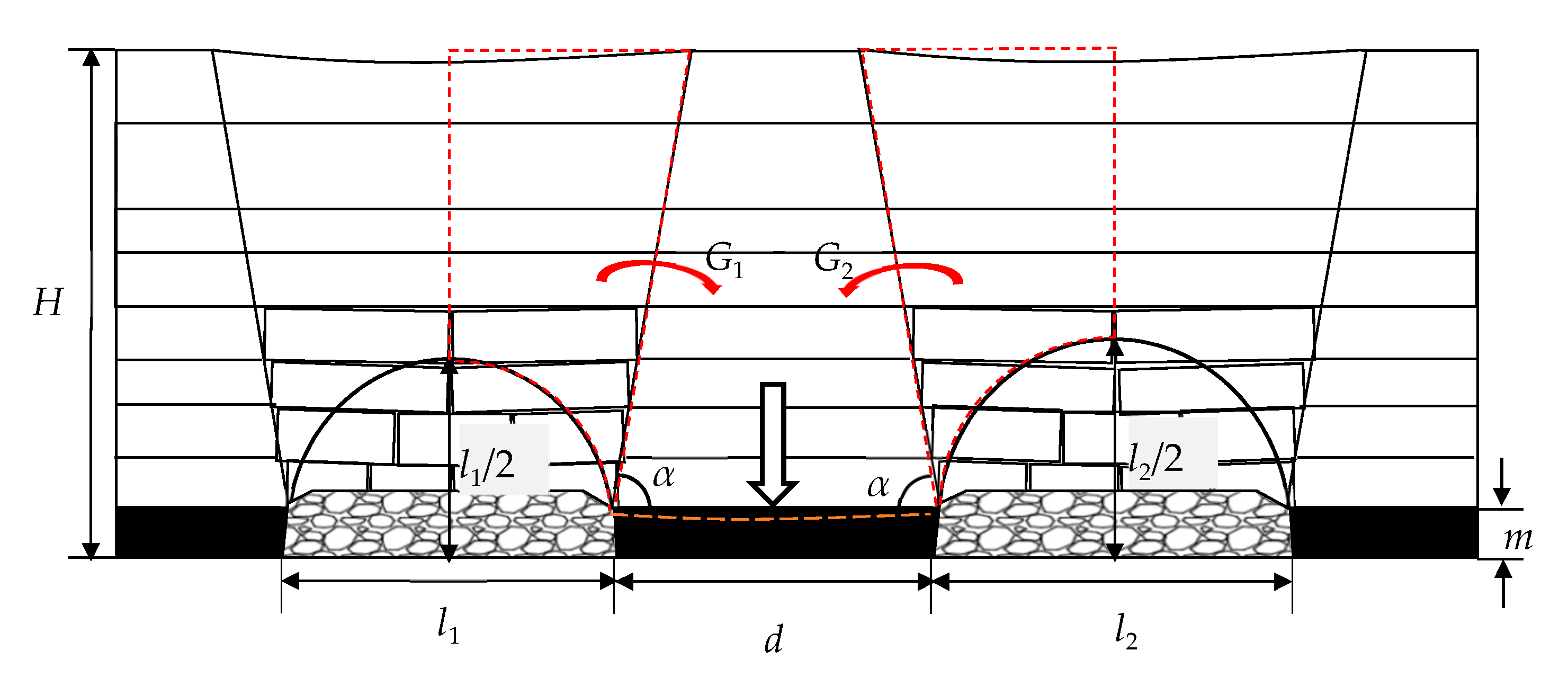
Before the mining on both sides of the ICP, the gravity stress of the overlying strata is the only stress source in the vertical direction, and the ICP, in a self-balanced state, will not undergo a deformation. With the mining on both sides completed, the ICP becomes an “island-like coal pillar”. The stress source above ICP changes from the gravity stress into the sum of the gravity stress and the transferred stress of the overlying strata in the goafs on both sides, which breaks ICP’s original self-balance. Under the influence of the new stress source, ICP will vertically generate a compressive deformation. According to previous studies [32,34,35], considering the relatively small subsidence coefficient in the mining area, the overlying strata are in the stage of insufficient mining after the first working faces of the two mining areas are extracted. Based on this, the mechanical calculation model of the stress transfer and the compression amount of the ICP under the condition of thick bedrock formation is established, as shown in Figure 7. Before the rock strata are fully exploited, the fracture height of the rock strata after mining is nearly one-half of the width of the goaf [19,23]. The overlying strata structures in the goafs are fully hanging, and the load transferred to the coal pillar is taken as one-half of the weight of the hanging strata [14,29,36]. Thus, the stress above ICP constitutes the transferred stress from the hanging strata and the gravity stress of the overlying strata. The angle α between the connecting line of the bottom of the goaf and the boundary of the moving zone of the strata and the horizontal plane is called the displacement angle of the strata.
In this model, the stress above the ICP is composed of G1 and G2 transmitted from the left and right goafs and the gravity G of the overlying strata after extraction:
Gt = G + G1 + G2
Here,
G = γ ( H d H 2 tan α )
G 1 = γ ( H l 1 2 + H 2 2 tan α π l 1 2 16 )
G 2 = γ ( H l 2 2 + H 2 2 tan α π l 2 2 16 )
In the above equations, γ is the specific weight of the overlying strata, H is the buried depth of coal seam, d is the width of isolated coal pillar, and l1 and l2 are the widths of goafs on two sides.
Before the two sides of the ICP are mined, the ICP is only subjected to the original rock stress and can remain self-balanced, and G0 = γHd. After the mining on both sides, the ICP is compressed and deformed. The mining-induced deformation amount of the ICP, s, can be represented as:
s = ε m = G t G 0 E 0 d 0 m
where m is the thickness of coal seam; ε is the compressive strain of the ICP in the vertical direction; E0 is the elasticity modulus of coal seam; and d0 is the width of the effective supporting zone of the ICP, which is obtained by the width of the ICP, d, minus the width of pressure-relief zones on both sides, d1.
The simultaneous equation including Equations (11)–(15) is given as follows:
s = γ m [ 8 H ( l 1 + l 2 ) π ( l 1 2 + l 2 2 ) ] 16 E E 0 d 0
It can be seen from Equation (16) that d0 is negatively correlated with s under the premise that the thickness of coal seam, the width of working faces on both sides, and the depth of pressure-relief borehole are fixed. In other words, the larger d0 is, the smaller s is.

3.3. Analysis of the Relationship Between the Compression of the ICP and the Flexural Deformation of the MKS

After the mining on both sides of the ICP, a compressive deformation appears in the coal pillar in the vertical direction due to the joint effect of the overlying rock strata’s gravity and the transferred stress from the overlying strata in the goafs on both sides. The soft rock strata above the ICP begin to fracture and subside along with the compressive deformation of the ICP until it reaches the high MKS. Since MKS itself does not easily break down, it suffers from a flexural deformation only driven by gravity. Whether it can reach the limited deflection is an important criterion for judging the fracture of the rock stratum. The following two situations are possible:
(1)
When wmaxs, the overlying high hard MKS undergoes a flexural deformation, but it still keeps full contact with the lower rock strata, supported by the ICP. This means that its flexural deformation does not reach the limited deflection and breaks will not arise.
(2)
When wmax < s, after ICP experiences a compressive deformation, the soft rock stratum breaks and dips down, MKS reaches its limited deflection, and a separated stratum with a large amount of elastic energy appears. Influenced by other disturbances, it easily breaks down, releases a great amount of energy, and leads to MS, which greatly affects the safety of underground production and the stability of ground buildings.
The above analysis indicates the mechanism of mining-induced seismicity on both sides of an ICP: After the mining on two sides of a ICP, it undergoes a vertical compressive deformation, and a flexural deformation occurs in the MKS. When the limited deflection of the stratum is smaller than the compression amount of coal pillar, the strata break down, and the energy released triggers the MS.

4. ICP Width Design Based on the Collaborative Control of MS and Rockburst

4.1. Width of the ICP Calculated Based on the Nonoccurrence of OII Rockbursts

The research results of Feng et al. [36] and Zhu et al. [29] illustrate that for the coal seam with a strong rockburst tendency, the bearing capacity of the coal pillar is easily less than the sum of the dead-weight of the overlying strata and the transmission load of the strata in the goafs when too small of a width is designed for the ICP between the mining areas or the mines. In this case, it is believed that OII rockbursts will probably take place. Due to the construction of large-diameter pressure-relief boreholes on the working faces on both sides of the coal pillar, the coal body in the destressed protective zone experiences a plastic failure, which weakens its bearing capacity. Therefore, the coal pillar is forced to be in a unidirectional stress state, and the strength is the UCS of the coal body, σc. The elastic bearing zone, restrained by the roof, the floor, and the coal bodies in the plastic zones on two sides, is in a three-dimensional stress state, presenting a strong bearing capacity, and its strength is the triaxial compressive strength, σ3c. For the convenience of calculation, the stresses above the plastic zone and the elastic bearing zone of the coal pillar are averaged, and then a calculation model of the average stress of the ICP is established, as demonstrated in Figure 8.
Under the principle of constant stress,
G t = 2 d 1 σ 1 + d 0 σ 2
Here, d1 is the width of the plastic zone, i.e., the depth of large-diameter pressure-relief boreholes; σ1 is the average bearing stress of the plastic zone; and σ2 is the average bearing stress of the elastic zone.
The large-diameter pressure-relief boreholes make the coal body in the plastic zone remain at a low stress level during the mining of the working face on both sides of the coal pillar, and the maximum stress it can receive is σ1 = σc. In order to prevent the coal pillar from experiencing OII rockbursts, it is necessary to ensure the average stress above the elastic bearing area is less than or equal to the strength of the elastic bearing area, that is to say, σ2σ3c, and the critical stress level is σ2 = σ3c. According to the Equations (11)–(14) and (17), the minimum width of the ICP on the basis of no OII rockbursts, dmin, can be calculated as follows:
d min = 32 d 1 ( σ 3 c σ c ) + 8 γ H ( l 1 + l 2 ) γ π ( l 1 2 + l 2 2 ) 16 ( σ 3 c γ H )

4.2. ICP Width Calculated Based on MS Prevention

The relatively thin and soft rock strata have a small self-stability span, while the overlying high MKS is characterized by a large self-stability span. Provided that the overlying high MKS can be self-stabilized after the mining on both sides of an ICP, according to the above-mentioned occurrence mechanism of MS, it is required to ensure that the MKS has full contact with the lower rock strata after the flexural deformation is generated, while ensuring that the limited deflection is not reached, so as to avoid such MS; the critical condition is wmax = s. Based on the Equations (10) and (16), the minimum width of an ICP for MS prevention, Dmin, is given as follows:
D min = 2 d 1 + 2 γ m E h 3 [ 8 H ( l 1 + l 2 ) π ( l 1 2 + l 2 2 ) ] 5 E q 0 L 4

4.3. ICP Width Design Basis

Different ICP widths may bring about different dynamic disasters. In view of the minimum widths of the coal pillar dmin and Dmin under the conditions of no OII rockbursts and no MS, respectively, the basis for judging whether different ICP widths may give rise to MS, OII rockbursts, or both is as follows:
(1)
If d < min { d min , D min } , both OII rockbursts and MS may be induced;
(2)
If min { d min , D min } d < max { d min , D min } , either OII rockbursts or MS may be induced;
(3)
If d max { d min , D min } , neither OII rockbursts nor MS will take place.
A reasonable design of ICPs aims to avoid the mining-induced mutual disturbance, reduce surface deformation, and control underground disasters, with the principle of ensuring the safety of underground production and the safety and stability of ground pipelines and buildings. The design basis is to realize the nonoccurrence of OII rockbursts and MS, and the ICP width should satisfy the condition d max { d min , D min } .

5. Verification by Theoretical Solution, Numerical Simulation Analysis, and Microseismic Monitoring

5.1. Verification by Theoretical Solution

According to the actual situation of LW2201 and LW2101 of Yingpanhao Coal Mine, we take H = 720 m, h = 324 m, δ = 6.88 MPa, μ = 0.25, l1 = 300 m, l2 = 300 m, d = 350 m, d1 = 20 m, d0 = 310 m, E = 28 GPa, E0 = 0.86 GPa, m = 6.4 m, α = 83°, γ =25 kN/m3, σc = 21 MPa, σ3c = 63 MPa (research findings [14,36] indicate that the triaxial compressive strength of coal body is roughly 3–5 times the UCS, and in this model, the triaxial strength is taken to be 3 times the UCS, i.e., σ3c = 3σc), H1 (the buried depth of MKS) = 420 m, and q (the overlying load) = γH1 = 10.5 MPa. The limited span of MKS is obtained based on Equation (1), that is, L (454 m) is greater than d (350 m). Equation (10) is used to determine the limited deflection of the rock beam with a limited span; here, wmax = 0.073 m. According to Equation (16), the mining-induced compression amount of ICP is determined and expressed as s = 0.11 m. Here, wmax < s. Therefore, when the two sides of ICP are mined to a certain extent, MKS reaches its limited deflection, and disturbances can easily trigger breaks and MS. Two MS events occurred on the LW2201 on 7 October 2018 and were strongly felt underground and on the surface, which verified the correctness of the calculation results.
The minimum width of ICP to prevent rockbursts from occurring, dmin, was determined to be 138 m according to Equation (18). According to Equation (19), the minimum width of the coal pillar under the principle of mine seismicity prevention, Dmin, was determined to be 498 m, approximately equal to 500 m. Because min { d min , D min } d < max { d min , D min } two MS events occurred in this mine on 7 October. Therefore, d ≥ 500 m can meet the requirements in reference to the previously mentioned width design method based on the absence of rockbursts and MS.

5.2. Verification by Numerical Simulation Analysis

Based upon the geological conditions of the 2-2 coal seam in Yingpanhao Coal Mine, the characteristics of stress distribution and the compressive deformation after the mining on both sides of the coal pillar were simulated by means of FLAC3D. The size of the established model was 1700 m × 2500 m × 120 m, and the four sides were fixed by displacement constraints, At the top of the model, a uniform load was applied to simulate the 610 m thick overburden weight, conforming to the Mohr–Coulomb failure criterion [37,38,39,40]. In the model, the black group is the coal seam, as shown in Figure 9.
LW2201 and LW2101, with a 300 m width, a 1500 m length, a 6 m thickness, and the same cutting point were chosen for the simulation. Different ICP widths, namely 150 m, 350 m and 500 m, were selected for analysis. The mechanical properties of the coal seam and each rock stratum were obtained from the borehole data and geological report of the mine.
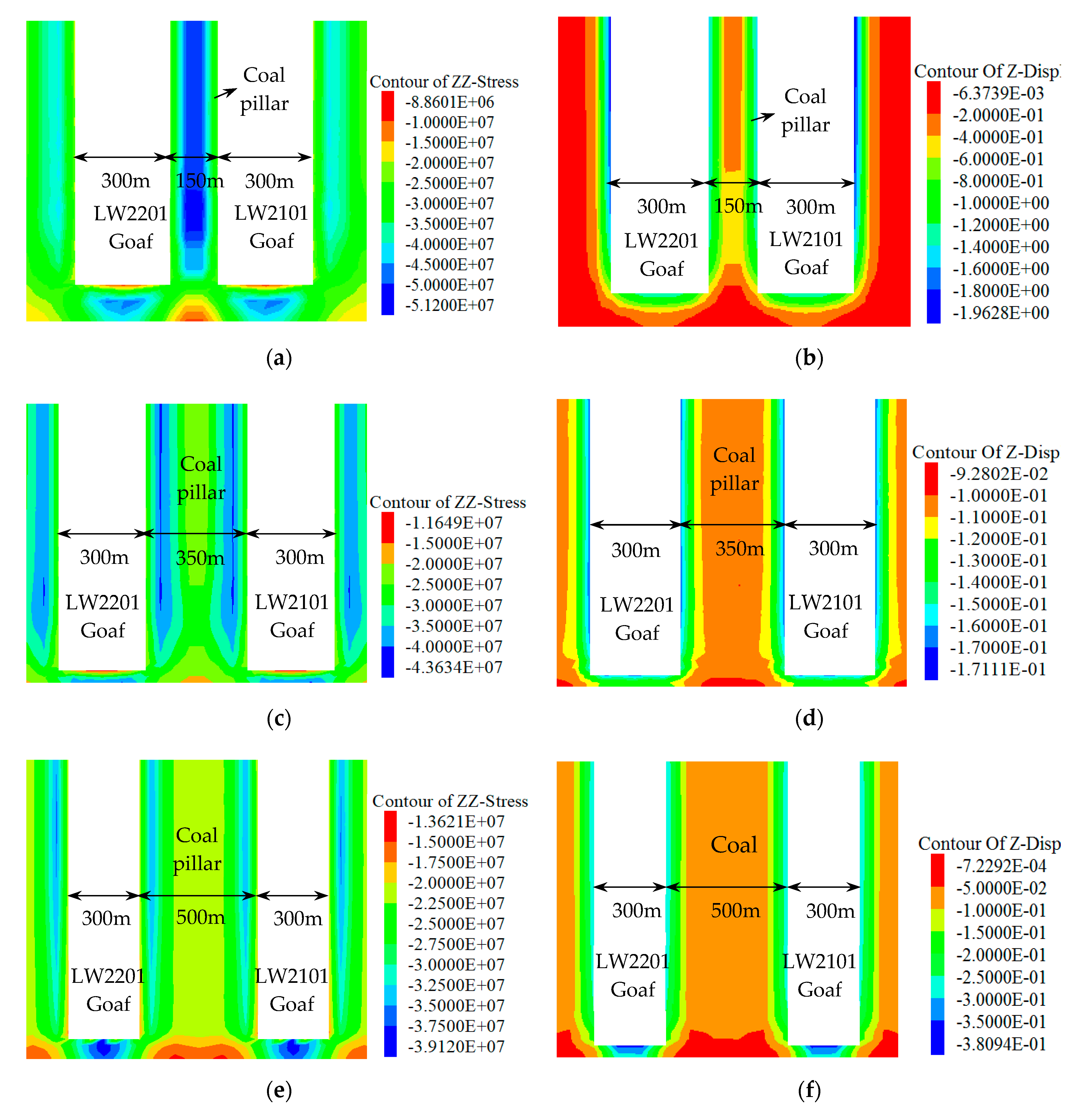
Figure 10 demonstrates the characteristics of vertical stress distribution and vertical compressive deformation of ICPs with different widths after mining on both sides. Figure 11 demonstrates the variation law of vertical stress distribution and compressive deformation amount of ICPs with different widths. It can be seen from Figure 10a,b that when the mining is started on both sides of the 150 m wide coal pillar, the maximum vertical stress above the coal pillar is 51.2 MPa, about 2.44 times the UCS of the coal body, and the minimum vertical compressive deformation is 0.364 m. According to Figure 11, it can be seen that the coal pillar has a high rockburst risk and probably induces MS. In the actual mining process, large-diameter pressure-relief boreholes were drilled along roadways on LW2201 and LW2101, which leads to a further increase in the concentrated stress above the coal pillar. This indicates that both OII rockbursts and MS will occur when the ICP width is less than 138 m. Figure 10c,d shows that after the mining on both sides of the 350 m wide coal pillar, the maximum vertical stress above the coal pillar is 39.8 MPa, equivalent to around 1.86 times the UCS of the coal body, and the large-scale vertical compressive deformation is 0.106 m, greater than the theoretical calculated value wmax. Here, the stress above the coal pillar cannot reach the condition of OII rockbursts; however, the deformation has exceeded the limited deflection of the MKS, and MS is easily induced. The results shown in Figure 10e,f suggest that after the mining on both sides of the 500 m wide coal pillar, the maximum vertical stress above the coal pillar is 34.2 MPa, nearly 1.63 times the UCS of the coal body, and the vertical compressive deformation is 0.062 m (wmax = 0.073 m > 0.062 m). Figure 11 shows that the condition of OII rockbursts is not satisfied, and MS does not exist either because the deformation amount is less than the limited deflection of the MKS. This verifies the correctness of the theoretical design basis.

5.3. Verification by Microseismic Monitoring Analysis

Research [41,42] has demonstrated that during the mining process, as the mining distance approximately equals the width of working face, “a working-face square” will appear. At this time, the fracture height of rock stratum and the lead abutment pressure in the stope reach their respective maximums, which is called the “working-face square effect”.
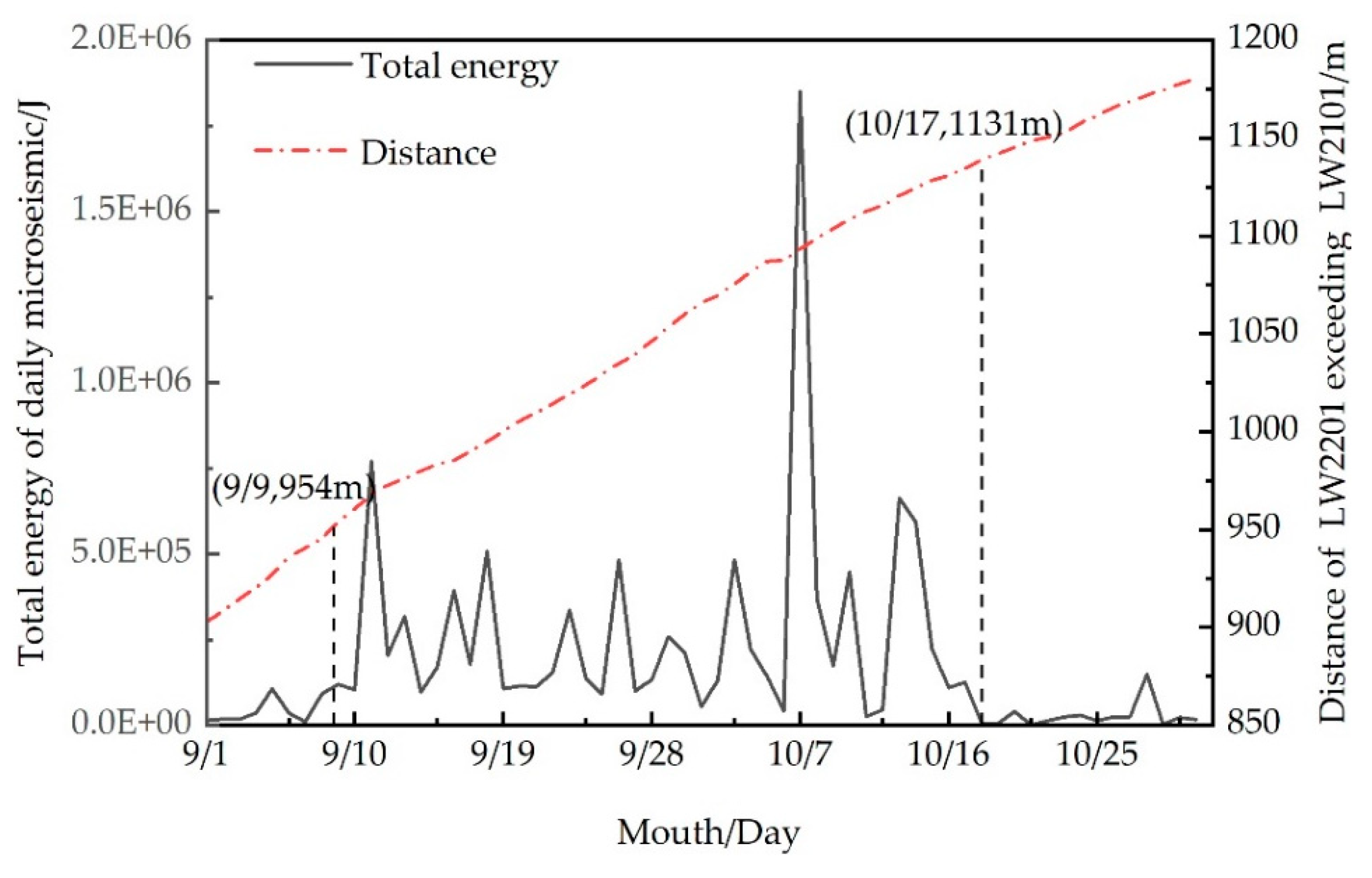
Figure 12 displays the relationship between the distance of LW2201 exceeding LW2101 and the daily change of microseismic energy from 1 September to 31 October 2018. It can be seen that the total microseismic energy before and after the mine seismicity on 7 October changed drastically; it kept a smooth rate of change from 1 to 9 September, but this rate began to increase significantly on 9 September until 17 October. It then started to decrease and tended to be stable. The total microseismic energy dramatically increased when the cutting point of LW2201 was 954–1131 m distant from that of LW2101. Analysis showed that this 954–1131 m range was just within the influencing scope of “a three-working-face square” composed of LW2201, LW2101, and ICP.
Figure 13 is the plane projection of microseismic events during the mining process from 1 September to 31 October 2018. The purple frame is the “three-working-face square” zone, and the red frame is the scope influenced by the “three-working-face square”. The comparison between the projections of the microseismic events on the LW2201 and LW2101 explains that more microseismic events were concentrated in the range of influence, and the large-energy events in this region were significantly more frequent than in other regions. It was proved that there was a “three-working-face square” effect after the mining on both sides of an ICP, which led to a higher concentration of stress above the coal pillar.
According to the strata structure above the 2-2 coal seam in Table 1, there is a superthick red sandstone group approximately 300 m above the working face (this sandstone group is an overlying high MKS) with a thickness of about 320 m. A 106 J energy event can only take place when the MKS fractures. Studies [19,23] have proven that before the rock stratum is fully mined, the fracture height of the rock stratum after mining is about one-half of the width of the goaf. The widths of LW2201 and LW2101 are both 300 m, and the theoretical value of the fracture height is 150 m, not reaching the MKS. However, the real situation of the on-site seismicity indicated that when the LW2201 advanced to the “three-working-face square” zone, the coal pillar produced a compressive deformation under the influence of the goafs on both sides, causing the thick red sandstone group above the coal pillar to break and lose stability because its limited deflection had been reached, and the energy released induced MS.

6. Conclusions

Taking the ICP of Yingpanhao Coal Mine in Inner Mongolia as the background engineering case study, this paper investigates the occurrence mechanism of MS resulting from the mining on both sides of ICPs by means of theoretical analysis, numerical simulation, and microseismic monitoring. It puts forward the design consideration of the ICP width based on the planned nonoccurrence of OII rockbursts and MS, and several main conclusions can be obtained, as detailed below.
We revealed the occurrence mechanism of MS induced by the mining on both sides of ICPs. After the mining on both sides of the coal pillar, a compressive deformation in the vertical direction appears in the coal pillar, and the overlying high MKS suffers from a flexural deformation. When the limited deflection of the rock stratum is less than the compression amount of the coal pillar, the MKS is easily broken by mining disturbance, and then the released energy induces MS.
We comprehensively considered the minimum width of the coal pillar necessary to prevent OII rockbursts, dmin, and calculated the minimum width of the coal pillar necessary to prevent mine seismicity after stoping on both sides, Dmin; we then provided the ICP width design based on the planned nonoccurrence of OII rockbursts and MS, that is, d max { d m i n , D m i n } .
We adopted the theoretical solution, microseismic monitoring, and numerical simulation to verify the occurrence mechanism of MS and the correctness of the ICP width design basis, and we further illustrated that d ≥ 500 m of the ICP in this mine can ensure that neither MS nor OII rockbursts occur. The research results may be used as a theoretical guidance for rational ICP design in deep mines with similar conditions, and they may help mitigate the risk of rockburst and MS from early mining stages.
This paper attempts to provide mine researchers and designers with a new design basis for ICPs, in an effort to reduce dynamic disasters in mining caused by unreasonable designs. However, the study only centers on the occurrence mechanism of MS under the condition of nonsufficient mining, so it is necessary to conduct further studies considering the case of sufficient mining. It is certain that continuous microseismic monitoring should be required during the mining process so as to predict the occurrence of MS and allow corresponding control measures to be taken, ensuring safe mining.

Author Contributions

B.W. and F.J. conceived and designed the research and provided theoretical guidance in the research process; S.Z. and J.L. performed the numerical simulation and field tests; B.W. and X.S. analyzed the data; B.W. and S.Z. wrote the paper; X.Z. provided some useful field data. All authors have read and agreed to the published version of the manuscript.

Funding

This work was supported, and financed, by the National Natural Science Foundation of China (Grant No. 51674014, 51904017, 51634001), the Major Scientific and Technological Innovation Projects in Shandong Province (No. 2019SDZY02), and the Fundamental Research Funds for the Central Universities (No. FRF-TP-20-002A2).

Acknowledgments

Special thanks should be extended to the Yingpanhao Coal Mine for the provided raw data. The authors thank the anonymous reviewers for constructive comments that helped to improve the quality of the paper.

Conflicts of Interest

The authors declare no conflict of interest.

References

  1. He, M.C.; Zhao, F.; Cai, M.; Du, S. A novel experimental technique to simulate pillar burst in laboratory. Rock Mech. Rock Eng. 2015, 48, 1833–1848. [Google Scholar] [CrossRef]
  2. Lu, C.P.; Liu, G.J.; Liu, Y.; Zhang, N.; Xue, J.H.; Zhang, L. Microseismic multi-parameter characteristics of rockburst hazard induced by hard roof fall and high stress concentration. Int. J. Rock Mech. Min. Sci. 2015, 76, 18–32. [Google Scholar] [CrossRef]
  3. Konicek, P.; Soucek, K.; Stas, L.; Singh, R. Long-hole destress blasting for rockburst control during deep underground coal mining. Int. J. Rock Mech. Min. Sci. 2013, 61, 141–153. [Google Scholar] [CrossRef]
  4. He, S.Q.; Song, D.Z.; Li, Z.L.; He, X.Q.; Chen, J.Q.; Zhong, T.P.; Lou, Q. Mechanism and Prevention of Rockburst in Steeply Inclined and Extremely Thick Coal Seams for Fully Mechanized Top-Coal Caving Mining and Under Gob Filling Conditions. Energies 2020, 13, 1362. [Google Scholar] [CrossRef] [Green Version]
  5. Wang, J.C.; Jiang, F.X.; Meng, X.J.; Wang, X.Y.; Zhu, S.T.; Feng, Y. Mechanism of Rock Burst Occurrence in Specially Thick Coal Seam with Rock Parting. Rock Mech. Rock Eng. 2016, 49, 1953–1965. [Google Scholar] [CrossRef]
  6. Li, Z.L.; He, X.Q.; Dou, L.M.; Song, D.Z.; Wang, G.F.; Xu, X.L. Investigating the mechanism and prevention of coal mine dynamic disasters by using dynamic cyclic loading tests. Saf. Sci. 2019, 115, 215–228. [Google Scholar] [CrossRef]
  7. Bräuner, G. Rockbursts in Coal Mines and Their Prevention; Routledge: London, UK, 2017. [Google Scholar]
  8. He, M.C.; Gao, Y.B.; Yang, J.; Gong, W.L. An innovative approach for gob-side entry retaining in thick coal seam longwall mining. Energies 2017, 10, 1785. [Google Scholar] [CrossRef] [Green Version]
  9. Wang, S.L.; Hao, S.P.; Chen, Y.; Bai, J.B.; Wang, X.Y.; Xu, Y. Numerical investigation of coal pillar failure under simultaneous static and dynamic loading. Int. J. Rock Mech. Min. Sci. 2016, 84, 59–68. [Google Scholar] [CrossRef]
  10. Liu, J.H.; Jiang, F.X.; Wang, N.G.; Li, Z.S.; Zhang, Z.G. Research on reasonable width of segment pillar of fully mechanized caving face in extra-thick coal seam of deep shaft. Chin. J. Rock. Mech. Eng. 2012, 31, 921–927. [Google Scholar]
  11. Cao, A.Y.; Dou, L.M.; Wang, C.B.; Yao, X.X.; Dong, J.Y.; Gu, Y. Microseismic precursory characteristics of rock burst hazard in mining areas near a large residual coal pillar: A case study from xu zhuang coal mine, Xuzhou, China. Rock Mech. Rock Eng. 2016, 49, 1943–1952. [Google Scholar] [CrossRef]
  12. Liu, G.J.; Mu, Z.L.; Chen, J.J.; Yang, J.; Cao, J.L. Rock burst risk in an island longwall coal face by stress field. Geosci. J. 2018, 22, 609–622. [Google Scholar] [CrossRef]
  13. Li, D.; Jiang, F.X.; Chen, Y.; Gai, D.C.; Wang, Y.; Wang, W.B. Study on impact mechanism and prevention technology of drainage lane of large coal pillars near deep wells. J. Min. Saf. Eng. 2019, 36, 265–271. [Google Scholar]
  14. Zhu, S.T.; Feng, Y.; Jiang, F.X. Determination of abutment pressure in coal mines with extremely thick alluvium stratum: A typical kind of rock burst mines in china. Rock Mech. Rock Eng. 2016, 49, 1943–1952. [Google Scholar] [CrossRef]
  15. Vizintin, G.; Kocjancic, M.; Vulic, M. Study of coal burst source locations in the velenje colliery. Energies 2016, 9, 507. [Google Scholar] [CrossRef] [Green Version]
  16. Cai, M.F.; He, M.C.; Liu, D.Y. Rock Mechanics and Engineering; Science Press: Beijing, China, 2002. [Google Scholar]
  17. Ju, Y.; Wang, Y.L.; Su, C.S.; Zhang, D.S.; Ren, Z.Y. Numerical analysis of the dynamic evolution of mining-induced stresses and fractures in multilayered rock strata using continuum-based discrete element methods. Int. J. Rock Mech. Min. Sci. 2019, 113, 191–210. [Google Scholar] [CrossRef] [Green Version]
  18. Zhang, C.; Canbulat, I.; Bruce, H.; Ward, C.R. Assessing coal burst phenomena in mining and insights into directions for future research. Int. J. Coal Geol. 2017, 179, 28–44. [Google Scholar] [CrossRef]
  19. Qian, M.G.; Miao, X.X. Theory research of critical layer in strata control. J. China Coal Soc. 1996, 21, 225–230. [Google Scholar]
  20. Pan, Y.S. Disturbance response instability theory of rockburst in coal mine. J. China Coal Soc. 2018, 43, 2091–2098. [Google Scholar]
  21. Zhang, T.K.; Pan, Y.S.; Xiao, Y.H.; Wang, A.W. Analytic solutions of a reducible strain gradient elasticity model for solid cylinder with a cavity and its application in zonal failure. Appl. Math. Model. 2019, 72, 663–681. [Google Scholar] [CrossRef]
  22. Jiang, F.X.; Zhang, X.M.; YANG, S.H.; Xun, L.; Ma, Q.H.; Wang, H.J. Discussion on overlying strata spatial structures of longwall in coal mine. Chin. J. Rock Mech. Eng. 2006, 25, 979–984. [Google Scholar]
  23. Jiang, F.X.; Liu, Y.; Zhang, Y.C.; Wen, J.L.; Yang, W.L.; An, J. A three-zone structure loading model of overlying strata and its application on rockburst prevention. Chin. J. Rock Mech. Eng. 2016, 35, 2398–2408. [Google Scholar]
  24. Hosseini, N. Evaluation of the rockburst potential in longwall coal mining using passive seismic velocity tomography and image subtraction technique. J. Seismol. 2017, 21, 1101–1110. [Google Scholar] [CrossRef]
  25. Cao, A.Y.; Zhu, L.L.; Li, F.C.; Dou, L.M.; Zhao, Y.L.; Zhang, Z.L. Characteristics of T-type overburden structure and tremor activity in isolated face mining under thick-hard strata. J. China Coal Soc. 2014, 39, 328–335. [Google Scholar]
  26. Cao, A.Y.; Jing, G.C.; Dou, L.M.; Gong, S.Y.; Zhao, Y.L.; Zhang, Z.L. Seismic hazard assessment in complex island coalface by computed tomography. J. Min. Saf. Eng. 2015, 32, 20–27. [Google Scholar]
  27. Li, Z.L.; He, X.Q.; Dou, L.M. Control measures and practice for rock burst induced by overburden fracture in top coal caving mining. J. China Univ. Min. Technol. 2018, 47, 162–171. [Google Scholar]
  28. Zhang, M.; Jiang, F.X.; Li, K.Q.; Wang, C.W.; Wu, X.G.; Gao, H.J.; Ji, S.H. Study of the compatible deformation and stability of the system of super thick strata and coal pillars. Chin. J. Rock Mech. Eng. 2017, 36, 326–334. [Google Scholar]
  29. Zhu, S.T.; Feng, Y.; Jiang, F.X.; Liu, J.H. Mechanism and risk assessment of overall-instability-induced rockbursts in deep island longwall panels. Int. J. Rock Mech. Min. Sci. 2018, 106, 342–349. [Google Scholar] [CrossRef]
  30. Mu, Z.L.; Dou, L.M.; Gong, S.Y.; Cao, A.Y. Networking design of sos micro-seismic monitoring for mine and error analysis of seismic resource orientation. Coal Min. Technol. 2009, 14, 8–14. [Google Scholar]
  31. Orlecka-Sikora, B.; Lasocki, S.; Lizurek, G.; Rudzinski, L. Response of seismic activity in mines to the stress changes due to mining induced strong seismic events. Int. J. Rock Mech. Min. Sci. 2012, 53, 151–158. [Google Scholar] [CrossRef]
  32. Reddish, D.J.; Whittaker, B.N. Subsidence: Occurrence, Prediction and Control; Elsevier: Amsterdam, The Netherlands, 2012. [Google Scholar]
  33. Jiang, F.X.; Wen, J.L.; Bai, W.S.; Wang, G.L.; Li, M. Rock burst risk in surrounding abscission layer of overlying high key strata in deep strip mining mines. J. China Univ. Min. Technol. 2018, 47, 40–47. [Google Scholar]
  34. Zhang, J.X.; Zhang, Q.; Sun, Q.; Gao, R.; Germain, D. Surface subsidence control theory and application to backfill coal mining technology. Environ. Earth Sci. 2015, 74, 1439–1448. [Google Scholar] [CrossRef]
  35. Shen, B.T.; Poulsen, B. Investigation of overburden behaviour for grout injection to control mine subsidence. Int. J. Min. Sci. Technol. 2014, 24, 317–323. [Google Scholar] [CrossRef]
  36. Feng, Y.; Jiang, F.X.; Li, J.D. Evaluation method of rock burst hazard induced by overall instability of island coal face. J. China Coal Soc. 2015, 40, 1001–1007. [Google Scholar]
  37. Labuz, J.F.; Zang, A. Mohr-Coulomb Failure Criterion. In the ISRM Suggested Methods for Rock Characterization, Testing and Monitoring: 2007–2014; Springer: Berlin, Germany, 2014; pp. 227–231. [Google Scholar]
  38. Zhao, H.C.; Kaunda, R.B. Numerical Assessment of the Influences of Gas Pressure on Coal Burst Liability. Energies 2018, 11, 260. [Google Scholar] [CrossRef] [Green Version]
  39. Feng, G.R.; Wang, P.F.; Chugh, Y.P. A New Gob-Side Entry Layout for Longwall Top Coal Caving. Energies 2018, 11, 1292. [Google Scholar] [CrossRef] [Green Version]
  40. Das, A.J.; Mandal, P.K.; Paul, P.S.; Sinha, R.K. Generalised Analytical Models for the Strength of the Inclined as well as the Flat Coal Pillars using Rock Mass Failure Criterion. Rock Mech. Rock Eng. 2019, 52, 3921–3946. [Google Scholar] [CrossRef]
  41. Henryk, G. The Theory of Strata Mechanics; Polish Scientific Publishers: Warszawa, Poland, 1991. [Google Scholar]
  42. Jiang, F.X.; Yang, S.H.; Xun, L. Spatial fracturing progresses of surrounding rock masses in longwall face monitored by microseismic monitoring techniques. J. China Coal Soc. 2003, 28, 357–360. [Google Scholar]
Figure 1. Layout diagram of isolated coal pillars (ICPs). A mining design using ICPs with different widths between neighboring working faces is preferred.
Energies 13 04293 g001
Figure 2. Rockburst regions of Yuncheng Coal Mine.
Energies 13 04293 g002
Figure 3. ICP and layout of working faces on both sides.
Energies 13 04293 g003
Figure 4. Waveforms of the two mine seismicities on 7 October: (a) 17:49 event; (b) 18:11 event.
Energies 13 04293 g004
Figure 5. (a) Plane projection drawing of the two MS events. (b) Roof deformation of the roadway.
Energies 13 04293 g005
Figure 6. Mechanical model of the flexural deformation of the main key stratum (MKS).
Energies 13 04293 g006
Figure 7. Estimation model of mining-induced compression amount of the isolated coal pillar.
Energies 13 04293 g007
Figure 8. Calculation model of average stress of the ICP.
Energies 13 04293 g008
Figure 9. Numerical model for simulation. The black group is the coal seam.
Energies 13 04293 g009
Figure 10. Characteristics of vertical stress distribution and compressive deformation amount of ICPs with different widths after mining on their two sides: (a) characteristics of vertical stress distribution above the 150 m wide coal pillar, (b) compressive deformation amount of the 150 m wide coal pillar, (c) characteristics of vertical stress distribution above the 350 m wide coal pillar, (d) compressive deformation amount of the 350 m wide coal pillar, (e) characteristics of vertical stress distribution above the 500 m wide coal pillar, and (f) compressive deformation amount of the 500 m wide coal pillar.
Energies 13 04293 g010
Figure 11. Variation law of vertical stress distribution and compressive deformation amount of ICPs with different widths.
Energies 13 04293 g011
Figure 12. Changing curve of microseismic total energy of the LW2201.
Energies 13 04293 g012
Figure 13. Plane projection of 9.1–10.31 microseismic events.
Energies 13 04293 g013
Table 1. Structural characteristics of rock strata above 2-2 coal seam.
Names of the RocksThickness/mAccumulated Depth/mColumnar FormsNote
Wind-blown sand95.7595.75 Sand on the surface
Sandstone group324.45420.2 Energies 13 04293 i001(Red layer) MKS
Interbedding of sandy mudstone and sandstone213.81634.01 Energies 13 04293 i002Soft rock strata
Sandstone group38.55672.56 Energies 13 04293 i003Inferior key stratum
Sandy mudstone7.52680.08 Energies 13 04293 i004Soft rock stratum
Medium sandstone19.47699.55 Energies 13 04293 i005Basic roof
Siltstone14.79714.34 Energies 13 04293 i006
2-2 coal6.13720.47 Energies 13 04293 i007Coal seam
Siltstone9.21729.68 Energies 13 04293 i008Basic bottom