Article

Syngas Composition: Gasification of Wood Pellet with Water Steam through a Reactor with Continuous Biomass Feed System

1
Faculty of Mechanical Engineering, Koszalin University of Technology, Raclawicka Str.15-17, 75-620 Koszalin, Poland
2
ENET Centre, VSB—Technical University of Ostrava, 17. Listopadu 2172/15, 708 00 Ostrava, Czech Republic
*
Author to whom correspondence should be addressed.
Energies 2020, 13(17), 4376; https://doi.org/10.3390/en13174376
Submission received: 15 July 2020 / Revised: 22 August 2020 / Accepted: 22 August 2020 / Published: 25 August 2020
(This article belongs to the Section L: Energy Sources)

Abstract

:
Investigations were performed in relation to the thermal gasification of wood granulate using steam in an allothermal reactor with electric heaters. They studied the impact of the temperature inside the reactor and the steam flow rate on the percentage shares of H2, CH4, CO, and CO2 in synthesis gas and on the calorific value of syngas. The tests were conducted at temperatures inside the reactor equal to 750, 800, and 850 °C and with a steam flow rate equal to 10.0, 15.0, and 20.0 kg∙h−1. The intensity of gasified biomass was 20 kg∙h−1. A significant impact of the temperature on the percentages of all the components of synthesis gas and a significant impact of the steam flow rate on the content of hydrogen and carbon dioxide in syngas were found. The highest percentage of hydrogen obtained was 43.3%. The calorific value of the gas depended significantly on the temperature inside the reactor and the correlation between the temperature and the steam flow rate. Its maximum value was 13.3 MJ∙m−3 at 800 °C. This paper also includes an assessment of the mutual correlations of the percentage shares of the individual synthesis gas components.

1. Introduction

Biomass can be used as a biorenewable resource of many advanced materials [1], but it is also a very important fuel recognized as a renewable energy source [2]. The direct combustion of some plant products in boilers may release many substances that are harmful to the environment [3]. The gasification of biomass at high temperatures enables the purification of the resulting gases before combustion and makes it possible to control the emission of pollutants. Thermal gasification can help destroy waste (e.g., municipal waste) and convert the energy contained in it into heat or electricity [4]. The simple biomass gasification in reactors through partial combustion in a limited air stream results in the production of a gas with a lower heat value (LHV), usually below 6 MJ∙Nm−3 [5,6]. Thermal gasification can be modified by introducing steam or oxygen instead of air into the gasifier, thus changing the composition of syngas produced [6,7,8,9,10,11,12,13]. In order to obtain the highest syngas energy value, attempts have been made to obtain the highest possible hydrogen and methane content and to minimize the share of carbon dioxide [12,14]. The high hydrogen content is achieved in the process of biomass gasification with the steam or thermal gasification of moist biomass [15,16,17,18].
The most popular raw materials used for the thermal gasification of biomass with the participation of water vapor is wood in various forms as sawdust, dust, chips, and granulates [9,19,20]. Apart from wood, typical cultivated energy crops [21] and waste biomass such as straw and hay [22,23], sewage sludge and manure [24,25,26] as well as biocarbon from previous biomass gasification may undergo steam gasification [12,27]. The raw materials for gasification may also include waste from the agri-food industry (e.g., oil production pomace [28], grape pomace [7], grain that was used in distilleries and in breweries [10,20,29], coffee hulls [30] and hazelnut shells [6]). Water steam gasification can be used not only in relation to biomass, but also in the process of the thermal gasification of hard coal, peat, and municipal waste as well as plastics [31,32,33,34,35]. Research is being carried out on the use of CO2 obtained from the combustion of syngas to increase the volume of syngas generated during the thermal gasification of municipal waste, particularly where increasing the CO2/steam ratio can facilitate the production of both CO and H2 in the resulting gas [33]. Research is also being conducted on the co-gasification of hard coal with biomass where a synergy effect was observed. The volume of hydrogen produced is increasing in relation to the gasification tests of the biomass and coal itself [31].
As a result of high-temperature biomass gasification including water steam gasification, the resulting gas is contaminated, mainly with dust and tar. In order to be introduced into turbines and combustion engines, especially into fuel cells, it must be purified [23,26]. The filter sets composed from the cyclones and porous materials are used to treat the mechanical impurities from fine particles in syngas. Very high gasification temperatures [36] and catalysts introduced into the system can also be used to remove chemical impurities [37,38]. Calcium compounds such as dolomite are most commonly used as CO2 and tar sorbents in the gasification process [26].
The share of water vapor in the thermal gasification of biomass can take place in various types of gasifiers. These can be autothermal gasifiers, where biomass is heated by means of heat obtained from partial combustion, and allothermal gasifiers, where heat is supplied from external sources [10,34,35]. Biomass was gasified with water steam in fixed-bed gasifiers and in reactors with a continuous flow of biomass and produced gas [21,23,31,38]. Biomass steam gasification was tested in a reactor with free biomass fall and lower syngas take-off [27] and in mono or dual fluidized bed reactors [8,9,24,29,33,39,40,41]. In autothermal fluidized bed gasifiers, a gasifying medium is used to maintain the particles in the suspension of the gas to be gasified. This is usually air or oxygen. In the case of the allothermal gasifier where steam is the only gasifying medium, steam is also used to support the fluidization process and to lift the particles [11,35].
Since the purpose of thermal gasification with water steam is to obtain synthesis gas with the highest possible calorific value, the aim is to convert carbon dioxide produced during gasification into carbon monoxide and methane and to use it to enrich syngas with hydrogen. Exothermic and endothermic reactions occurring during this process are described by chemical equations cited by the authors in [11,21,25,35,42]. The most important chemical reaction equations are the following:
Char oxidation:
C + O 2 CO 2
Boudouard reaction:
CO 2 + C 2 CO
Water–gas shift reaction:
CO + H 2 O CO 2 + H 2
Water–gas reaction:
C + H 2 O CO + H 2
Thermal cracking:
C n H m C + C x H y + H 2
Based on the thermodynamic equilibrium equations, mass and energy balances, and dedicated computer software, attempts have been made to model the gasification processes, while taking into account the individual stages of the process [40,42,43,44]. The results of the experimental and model investigations that have been conducted to date indicate that there are optimal ranges for the steam content in the gasifying medium. This was found, among others, during gasification with an air–steam mixture [7]. The results demonstrated that the composition of synthesis gas produced during water steam gasification and its calorific value as well as the relations between the shares of H2 and CO contained therein, may depend on the gasification temperature and the steam to biomass ratio [11,13,18,40].
Many experiments concerning biomass gasification with steam were carried out in autothermal reactors with the use of air or oxygen mostly in small laboratory gasifiers. The novelty of this work is that the research was carried out in an installation with a large reactor with a continuous biomass feed system to obtain pure syngas with a high concentration of methane and hydrogen.
The aim of the research was to determine the influence of temperature in the allothermal flow reactor and the influence of the steam flow rate to the reactor, to the synthesis gas composition and its lower heat value. Steam together with the heat generated in the reactor heating sets were the gasifying factors. An analysis of the percentage shares of the following gases was planned: H2, CH4, CO, CmHn as well as CO2 and O2 in the expected synthesis gas composition.

2. Materials and Methods

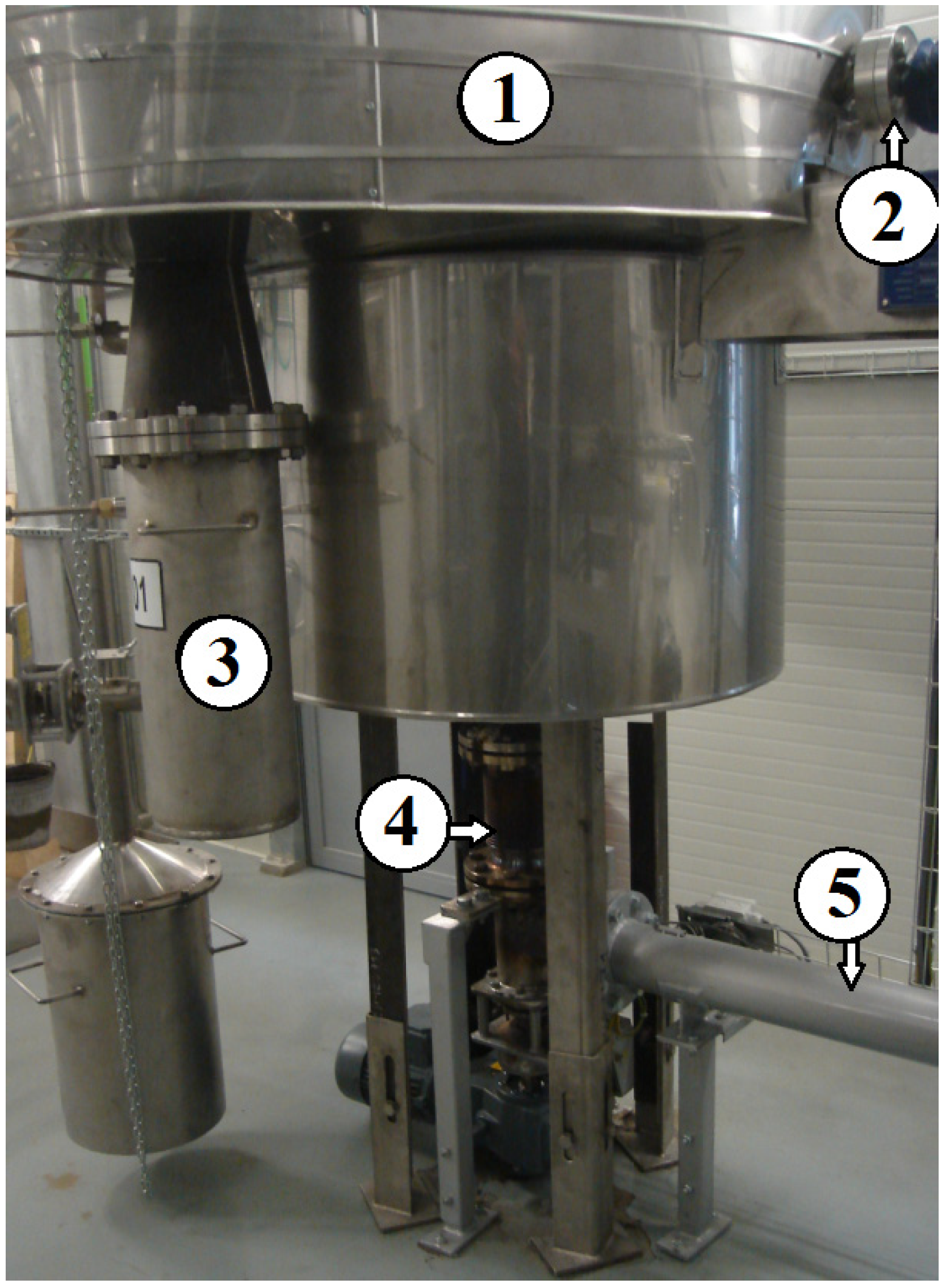
2.1. Gasification Installation

The research was carried out on an installation for thermal biomass gasification located in the Energy Research Center of the VŠB-Technical University of Ostrava, which produces syngas used to drive power generators. The installation consisted of an electrically heated reactor with a continuous supply of biomass and steam, a set of devices for cleaning and cooling synthesis gas, and a gas composition analyzer. A view of the gasification reactor is shown in Figure 1.
The reactor was heated from below by means of a 20 kW oval electric heater and from above by means of five bar heaters with a total power of 35 kW. Thermocouples for temperature measurements were installed in the lower and upper parts of the reactor to allow temperature adjustments inside the reactor. During the tests, the temperature was recorded in the upper part of the reactor, directly over the bed. The material subjected to gasification as the biomass was wood pellets, fed by means of a biomass feeder, with flow scales installed to control the rate of the biomass feed. From the feeder, the pellets were fed into the reactor from below, onto a moving grate, using horizontal and vertical screw conveyors. After the biomass was incinerated, the ash fell from the grate to the bottom of the reactor, from which it was removed by means of a screw conveyor to a closed metal container. The tank was emptied at the end of the experiment. The design of the reactor prevented any uncontrolled air from entering it from the outside.
The steam was produced by means of an electric generator. The rate of steam flow into the generator was adjusted by valves and by means of a flow meter mounted on a pipe with water flowing into the steam generator. The temperature of the water vapor supplied from the generator to the reactor was 650 °C. A diagram of the complete biomass thermal gasification plant including the equipment for gas treatment and analysis is shown in Figure 2.
The syngas produced in the installation was designed to drive a power generator driven by a combustion engine. In order to meet the requirements concerning the purity of the gas used to power the engine, the syngas was cleaned by means of a set of multiple devices [45]. Dust was removed by means of a cyclone separator (marked with the number 3) and with a dust filter (No. 6). A reactor with a dolomite catalyst was used to eliminate tar from the gas. The gas temperature was reduced by passing it through a water cooler fed with running water from a water system and ice water coolers. The installation was designed and constructed in cooperation with the Czech company ATEKO a.s.

2.2. Materials

A constant flow rate of the wood pellet into the generator was accepted for the purpose of this study, which was 20 kg∙h−1. The laboratory-determined physical parameters of the pellets are shown in Table 1. The elemental composition of the granulate is shown in Table 2.
The flow rate of steam into the generator was adjusted to 10.0, 15.0, and 20.0 kg∙h−1. The ratio of the steam rate to the rate of the biomass of pellets introduced into the S/B reactor was 0.5, 0.75, and 1.0, respectively.

2.3. Methods

A Portable Syngas Analyzer Gas 3100 was used to measure the percentage composition of the generator gas. The analyzer was connected to a pipe with cooled and purified gas coming out of the installation. The gas samples were collected by means of a ball valve probe equipped with a heated fiberglass filter trap, where solids and some tar particles were captured. Then, the gas flowed through vessels filled with isopropanol, where tar residues were removed from the gas. The gas then passed through three covered dishes placed in a freezer, where all the remaining organic substances and moisture were precipitated. With the help of the analyzer, the contents of CO, CO2, CH4, H2, O2, and CnHm in the synthesis gas were recorded continuously. The tests of the gas composition were performed with three temperatures set inside the reactor at 750, 800, and 850 °C.
All parameters were measured continuously during the experiment and recorded by a computer. The test measurements were made after the set temperature inside the reactor had been reached and stabilized and after the steam flow rate and gas discharge pressure had been reached. The data were recorded once every minute for the measurement period of 10 min.
The research was carried out on at installation for thermal biomass gasification located in the Energy Research Center of the VŠB—Technical University of Ostrava, which produces syngas used to drive power generators.

3. Results and Discussion

The results of all the measurements of the concentrations of the gases tested, with each temperature and with each rate of steam flow, showed hydrogen, methane, hydrocarbon, carbon dioxide, and carbon monoxide contents and no free oxygen O2 content was found. The presence of CnHm hydrocarbons in syngas was negligible, never exceeding 0.8%. At a temperature of 850 °C, the content of this gas was equal to “0” for all the vapor flow rates and did not exceed 0.2% at 750 °C; hence, a decision was made to omit its content as a separate gas for further analyses and to add the CnHm concentrations determined in the syngas to the CH4 concentration.
The averaged measurement results for the determined values of the temperature in the reactor and the steam flow rates are presented in Table 3. The results of the measurements of the percentage share of hydrogen, methane, carbon dioxide, and carbon monoxide in synthesis gas underwent a two-factor analysis of variance in order to determine the significance of the impact of the following: the steam outflow rate in the reactor and the temperature inside the reactor on the changes in the concentration of these components in the gas obtained.

3.1. Impact of the Steam Flow Rate on the Concentration of Synthesis Gas Components

The impact of the steam flow rate on the concentrations of synthesis gas components is shown in Figure 3, which presents the average percentage shares of synthesis gas components calculated on the basis of the values obtained for all tested temperatures.
The Figure 3 shows the calculated values of the least significant differences (LSD) for each of these gases. These values make it possible to find the value of the steam flow rate at which a significant difference in the gas composition occurred.
No significance of the impact of the steam flow rate on the percentage of CO and CH4 in the synthesis gas was found. However, the impact of the steam flow rate on the CO2 and H2 concentrations was found to be significant. An increase in the steam flow rate in the reactor caused an increase in carbon dioxide and a decrease in hydrogen content. The optimum hydrogen content, an average of 39.5%, was observed with the steam flow rate of 10 kg∙h−1, which corresponded to the S/B ratio of 0.5. Similar results were presented in [25,31]. In other studies on the thermal gasification of biomass with steam, with or without air, the maximum share of hydrogen content in syngas was obtained at higher S/B values [7,10,11,40].

3.2. Impact of the Temperature on the Concentration of Synthesis Gas Components

Based on the values obtained for all tested steam flow ratios, the average percentage shares of the gases included in the synthesis gas were determined for particular temperatures in order to assess the significance of the impact of the temperature in the generator on the composition of the gas. The least significant differences were determined for each of these syngas ingredients at the significance level of p < 0.05.
Using the calculated values of the least significant differences to compare the changes in the contents of the individual gases depending on the temperature inside the reactor, it can be noted that a significant decrease in hydrogen content in the synthesis gas occurred between 750 and 800 °C. The highest percentage share of H2 in the synthesis gas was 43.3% and it occurred at the lowest reactor temperature of 700 °C. The methane content of synthesis gas increased significantly between 750 and 800 °C and then decreased between 800 and 850 °C. The carbon dioxide content increased significantly between 800 and 850 °C. The carbon monoxide content increased significantly at 800 °C, and then returned to the previous level at 850 °C (Figure 4).

3.3. Impact of Reactor Temperature and the Steam Flow Rate on the Syngas Heat Value

The results of the syngas calorific value determined with the GAS 3100 Syngas gas analyzer were also covered by a two-factor variance analysis to calculate the significance of the impact of the steam flow rate and the temperature inside the reactor on the syngas energy value. The analysis demonstrated the significance of the impact of the temperature and the significance of the impact of the temperature and steam flow rate correlation on the syngas calorific value. A diagram that shows the impact of the temperature in the reactor on the lower heat value of synthesis gas is shown in Figure 5.
No significance was found in the impact of the steam flow rate alone on the changes in the syngas heat value. The maximum lower heat value of the synthesis gas was obtained at 800 °C. A further increase in temperature up to 850 °C in the generator resulted in a decrease in the heat value of the gas generated. By analyzing the composition of syngas at this temperature, it can be concluded that the decrease in the energy value was influenced by the increase in the percentage of CO2 and the decrease in the CO and CH4 contents.
The impact of the correlation between the reactor temperature and the steam outflow rate on the syngas heat value is shown in Figure 6. The calorific value of synthesis gas obtained at the level of 13.3 MJ∙m−3 at the temperature of 800 °C, and the steam inflow rate of 15.0 and 20.0 kg∙h−1 was typical for the thermal gasification of biomass with these conditions [6,13].

3.4. Correlations between the Content of the Individual Syngas Components

The basic components of gasified wood biomass and introduced water vapor such as O2, H2, and C were in the reactor. The amount and the percentage content of the produced gases that constitute the components of the syngas obtained in the reactor result directly from the mass flow rate of steam and biomass, the temperature in the reactor, and the chemical processes described by Equations (1)–(5), which took place during the gasification in the reactor. An analysis of the mutual correlations between the percentage contents of individual gases was carried out, taking into account the results of all measurements. Figure 7 and Figure 8 show the percentage changes of carbon monoxide and carbon dioxide contents in the syngas with an increasing methane percentage content.
The CO content increased with the growing CH4 content. This relationship is described in the following regression equation:
CO = 10.552 + 0.81718 · CH 4
with the calculated correlation coefficient r = 0.56371 at the significance level of p = 0.95.
In the case of CO2, the content of this gas decreased significantly as the CH4 content increased. The regression equation is determined as follows:
CO 2 = 46.859 1.518 · CH 4
with the correlation coefficient r = −0.7606, at the significance level p = 0.95.
The relation between the CO2 and CO content is shown in Figure 9. The following regression equation was determined:
CO 2 = 37.385 0.5313 · CO
with the correlation coefficient r = −0.3859 at the significance level of p = 0.95.
An attempt to find the relation between CH4 and H2 is shown in Figure 10.
The following regression equation was determined:
CH 4 = 18.278 0.1145 · H 2
with the correlation coefficient r = −0.2155 at the significance level of p = 0.95.
Correlations between the carbon monoxide and carbon dioxide contents, depending on the proportion of the hydrogen share, are shown in Figure 11 and Figure 12. The relations can be described by the following regression equations:
CO = 42.023 0.5270 · H 2
with the correlation coefficient r = −0.6842 at the significance level of p = 0.95,
CO 2 = 38.841 0.3435 · H 2
with the correlation coefficient r = −0.3239 at the significance level of p = 0.95.
The determined equations demonstrate a decrease in the carbon monoxide and carbon dioxide contents as the hydrogen content of the syngas increases.
Strong relations, with a correlation coefficient higher than 0.5, occurred between the CO and CO2 contents in relation to the CH4 content, and between the CO content in relation to the H2 content.

4. Conclusions

The main components of the synthesis gas obtained as the result of the thermal gasification of wood granulate with steam are represented by the following gases: CO, CO2, CH4, and H2. The value of the content of these gases in the gas generated was significantly influenced by the temperature in the gas generator. An increase in the temperature between 750 and 850 °C had a significant impact on the decrease of the H2, CH4, and CO content and on the increase of the CO2 content.
A significant impact of the steam flow rate on the concentration of H2 and CO2 in the synthesis gas was found. An increase in the steam flow rate in the generator caused a decrease in the share of hydrogen and an increase in the share of carbon dioxide in the syngas.
There was a significant impact of the temperature of the gas generator on the calorific value of the syngas. The highest calorific value of the synthesis gas was obtained at 800 °C.
This study has documented the existence of strong correlations between the carbon monoxide and carbon dioxide contents and methane content as well as between the carbon monoxide content and hydrogen content.
The research on the thermal gasification of wood granulate using steam, carried out in an electrically heated flow reactor, has confirmed the significance of the impact of the following factors: the flow rate of steam supplied to the reactor and the temperature inside the reactor on the percentage share of the components of the syngas produced such as H2, CH4, CO, and CO2. The research has demonstrated a possibility of adjusting the values of these factors while obtaining the required syngas composition and considering its maximum calorific value.

Author Contributions

Conceptualization, J.C. and J.N.; methodology, J.C., J.N., K.R. and V.P.; software, B.B.; validation, J.C., K.R. and J.K.; formal analysis, J.K. and K.R.; data curation, J.C. and V.P.; writing—original draft preparation, J.C., V.P. and J.N.; writing—review and editing, J.C., K.R., B.B. and J.K.; visualization, B.B.; supervision, J.N.; project administration, J.C.; funding acquisition, J.C. and J.K. All authors have read and agreed to the published version of the manuscript.

Funding

The research was performed within the framework of a project of bilateral exchange of researchers between the Republic of Poland and the Czech Republic titled “Use of catalysts to reduce emissions from the combustion of waste biomass” (reference no: PPN/BIL/2018/1/00074) co-financed in Poland by the NAWA, National Agency of Academic Exchange and supported by the Ministry of Education, Youth, and Sports of the Czech Republic under OP RDE grant number CZ.02.1.01/0.0/0.0/16_019/0000753 “Research center for low-carbon energy technologies”.

Acknowledgments

The authors would like to thank Associate Professor Tadeas Ochodek, Director of the Energy Research Center of VŠB-Technical University of Ostrava, for making the laboratory available for carrying out tests and providing assistance during their performance.

Conflicts of Interest

The authors declare no conflict of interest.

References

  1. Ates, B.; Koytepe, S.; Ulu, A.; Gurses, C.; Thakur, V.K. Chemistry, Structures, and Advanced Applications of Nanocomposites from Biorenewable Resources. Chem. Rev. 2020. [Google Scholar] [CrossRef] [PubMed]
  2. Lisy, M.; Lisa, H.; Jecha, D.; Balas, M.; Krizan, P. Characteristic properties of alternative biomass fuels. Energies 2020, 13, 1448. [Google Scholar] [CrossRef] [Green Version]
  3. Chojnacki, J.; Ondruska, J.; Kuczynski, W.; Soos, L.; Balasz, B. Emissions from the combustion of solid biofuels. In Proceedings of the 9th International Scientific Symposium on Farm Machinery and Process Management in Sustainable Agriculture, Lublin, Poland, 22–24 November 2017; pp. 70–75. [Google Scholar]
  4. Balas, M.; Lisy, M.; Kracik, P.; Pospisil, J. Municipal solid waste gasification within waste-to-energy processing. MM Sci. J. 2017, 1783–1788. [Google Scholar] [CrossRef]
  5. Najser, J.; Ochodek, T.; Chlond, R. Functioning of installation for a biomass gasification and economic aspects of electricity generation. Rynek Energii 2009, 6, 68–74. [Google Scholar]
  6. Gallucci, F.; Liberatore, R.; Sapegno, L.; Volponi, E.; Venturini, P.; Rispoli, F.; Paris, E.; Carnevale, M.; Colantoni, A. Influence of oxidant agent on syngas composition: Gasification of hazelnut shells through an updraft reactor. Energies 2020, 13, 102. [Google Scholar] [CrossRef] [Green Version]
  7. Hernández, J.J.; Aranda, G.; Barba, J.; Mendoza, J.M. Effect of steam content in the air-steam flow on biomass entrained flow gasification. Fuel Process. Technol. 2012, 99, 43–55. [Google Scholar] [CrossRef]
  8. Campoy, M.; Gómez-Barea, A.; Vidal, F.B.; Ollero, P. Air-steam gasification of biomass in a fluidised bed: Process optimisation by enriched air. Fuel Process. Technol. 2009, 90, 677–685. [Google Scholar] [CrossRef]
  9. Lv, P.M.; Xiong, Z.H.; Chang, J.; Wu, C.Z.; Chen, Y.; Zhu, J.X. An experimental study on biomass air-steam gasification in a fluidized bed. Bioresour. Technol. 2004, 95, 95–101. [Google Scholar] [CrossRef]
  10. Ferreira, S.; Monteiro, E.; Brito, B.; Castro, C.; Calado, L.; Vilarinho, C. Experimental analysis of brewers’ spent grains steam gasification in an allothermal batch reactor. Energies 2019, 12, 912. [Google Scholar] [CrossRef] [Green Version]
  11. Niu, Y.; Han, F.; Chen, Y.; Lyu, Y.; Wang, L. Experimental study on steam gasification of pine particles for hydrogen-rich gas. J. Energy Inst. 2017, 90, 715–724. [Google Scholar] [CrossRef]
  12. Sattar, A.; Leeke, G.A.; Hornung, A.; Wood, J. Steam gasification of rapeseed, wood, sewage sludge and miscanthus biochars for the production of a hydrogen-rich syngas. Biomass Bioenergy 2014, 69, 276–286. [Google Scholar] [CrossRef]
  13. Jangsawang, W.; Klimanek, A.; Gupta, A.K. Enhanced yield of hydrogen from wastes using high temperature steam gasification. J. Energy Resour. Technol. 2006, 128, 179–185. [Google Scholar] [CrossRef] [Green Version]
  14. Acharya, B.; Dutta, A.; Basu, P. An investigation into steam gasification of biomass for hydrogen enriched gas production in presence of CaO. Int. J. Hydrogen Energy 2010, 35, 1582–1589. [Google Scholar] [CrossRef]
  15. Gao, N.; Li, A.; Quan, C. A novel reforming method for hydrogen production from biomass steam gasification. Bioresour. Technol. 2009, 100, 4271–4277. [Google Scholar] [CrossRef] [PubMed]
  16. Valente, A.; Iribarren, D.; Gálvez-Martos, J.L.; Dufour, J. Robust eco-efficiency assessment of hydrogen from biomass gasification as an alternative to conventional hydrogen: A life-cycle study with and without external costs. Sci. Total Environ. 2019, 650, 1465–1475. [Google Scholar] [CrossRef] [PubMed]
  17. Schmieder, H.; Abeln, J.; Boukis, N.; Dinjus, E.; Kruse, A.; Kluth, M.; Petrich, G.; Sadri, E.; Schacht, M. Hydrothermal gasification of biomass and organic wastes. J. Supercrit. Fluids 2000, 17, 145–153. [Google Scholar] [CrossRef]
  18. Siwal, S.S.; Zhang, O.; Sun, C.; Thakur, S.; Gupta, V.K.; Thakur, V.K. Energy production from steam gasification processes and parameters that contemplate in biomass gasifier—A review. Bioresour. Technol. 2020, 297, 1–11. [Google Scholar]
  19. Umeki, K.; Yamamoto, K.; Namioka, T.; Yoshikawa, K. High temperature steam-only gasification of woody biomass. Appl. Energy 2010, 87, 791–798. [Google Scholar] [CrossRef]
  20. Meng, X.; de Jong, W.; Fu, N.; Verkooijen, A.H.M. Biomass gasification in a 100 kWth steam-oxygen blown circulating fluidized bed gasifier: Effects of operational conditions on product gas distribution and tar formation. Biomass Bioenergy 2011, 35, 2910–2924. [Google Scholar] [CrossRef]
  21. Howaniec, N.; Smoliński, A. Steam gasification of energy crops of high cultivation potential in Poland to hydrogen-rich gas. Int. J. Hydrogen Energy 2011, 36, 2038–2043. [Google Scholar] [CrossRef]
  22. Murakami, K.; Kasai, K.; Kato, T.; Sugawarab, K. Conversion of rice straw into valuable products by hydrothermal treatment and steam gasification. Fuel 2012, 93, 37–43. [Google Scholar] [CrossRef]
  23. Mikeska, M.; Najser, J.; Peer, V.; Frantik, J.; Kielar, J. Quality assessment of gas produced from different types of biomass pellets in gasification process. Energy Explor. Exploit. 2020, 38, 406–416. [Google Scholar] [CrossRef] [Green Version]
  24. Schweitzer, D.; Gredinger, A.; Schmid, M.; Waizmann, G.; Beirow, M.; Spörl, R.; Scheffknecht, G. Steam gasification of wood pellets, sewage sludge and manure: Gasification performance and concentration of impurities. Bioresour. Technol. 2018, 111, 308–319. [Google Scholar] [CrossRef]
  25. Hussein, M.S.; Burra, K.G.; Amano, R.S.; Gupta, A.K. Effect of oxygen addition in steam gasification of chicken manure. Fuel 2017, 189, 428–435. [Google Scholar] [CrossRef] [Green Version]
  26. Roche, E.; de Andrés, J.M.; Narros, A.; Rodríguez, M.E. Air and air-steam gasification of sewage sludge. The influence of dolomite and throughput in tar production and composition. Fuel 2014, 115, 54–61. [Google Scholar] [CrossRef]
  27. Wei, L.; Xu, S.; Zhang, L.; Liu, C.; Zhu, H.; Liu, S. Steam gasification of biomass for hydrogen-rich gas in a free-fall reactor. Int. J. Hydrogen Energy 2007, 32, 24–31. [Google Scholar] [CrossRef]
  28. Nipattummakul, N.; Ahmed, I.I.; Gupta, A.K.; Kerdsuwan, S. Hydrogen and syngas yield from residual branches of oil palm tree using steam gasification. Int. J. Hydrogen Energy 2011, 36, 3835–3843. [Google Scholar] [CrossRef]
  29. Kumar, A.; Eskridge, K.; Jones, D.B.; Hanna, M.A. Steam-air fluidized bed gasification of distillers grains: Effects of steam to biomass ratio, equivalence ratio and gasification temperature. Bioresour. Technol. 2009, 100, 2062–2068. [Google Scholar] [CrossRef]
  30. Wilson, L.; John, G.R.; Mhilu, C.F.; Yang, W.; Blasiak, W. Coffee husks gasification using high temperature air/steam agent. Fuel Process. Technol. 2010, 91, 1330–1337. [Google Scholar] [CrossRef]
  31. Howaniec, N.; Smoliński, A.; Stańczyk, K.; Pichlak., M. Steam co-gasification of coal and biomass derived chars with synergy effect as an innovative way of hydrogen-rich gas production. Int. J. Hydrogen Energy 2011, 36, 14455–14463. [Google Scholar] [CrossRef]
  32. Yu, J.; Tian, F.-J.; Chow, M.C.; McKenzie, L.J.; Li, C.-Z. Effect of iron on the gasification of Victorian brown coal with steam: Enhancement of hydrogen production. Fuel 2006, 85, 127–133. [Google Scholar] [CrossRef]
  33. Zheng, X.; Ying, Z.; Wang, B.; Chen, C. Hydrogen and syngas production from municipal solid waste (MSW) gasification via reusing CO2. Appl. Therm. Eng. 2018, 144, 242–247. [Google Scholar] [CrossRef]
  34. Pfeifer, C.; Koppatz, S.; Hofbauer, H. Steam gasification of various feedstocks at a dual fluidised bed gasifier: Impacts of operation conditions and bed materials. Biomass Conv. Bioref. 2011, 1, 39–53. [Google Scholar] [CrossRef]
  35. Pinto, F.; Franco, C.; André, R.N.; Tavares, C.; Dias, M.; Gulyurtlu, I.; Cabrita, I. Effect of experimental conditions on co-gasification of coal, biomass and plastics wastes with air/steam mixtures in a fluidized bed system. Fuel 2003, 82, 1967–1976. [Google Scholar] [CrossRef]
  36. Stąsiek, J.; Szkodo, M. Thermochemical conversion of biomass and municipal waste into useful energy using advanced hitag/hitsg technology. Energies 2020, 13, 4218. [Google Scholar] [CrossRef]
  37. Udomsirichakorn, J.; Basu, P.; Salam, P.A.; Acharya, B. Effect of CaO on tar reforming to hydrogen-enriched gas with in-process CO2 capture in a bubbling fluidized bed biomass steam gasifier. Int. J. Hydrogen Energy 2013, 38, 14495–14504. [Google Scholar] [CrossRef]
  38. Erkiaga, A.; Lopez, G.; Amutio, M.; Bilbao, J.; Olazar, M. Steam gasification of biomass in a conical spouted bed reactor with olivine and γ-alumina as primary catalysts. Fuel Process. Technol. 2013, 116, 292–299. [Google Scholar] [CrossRef]
  39. Chang, A.C.C.; Chang, H.F.; Lin, F.J.; Lin, K.H.; Chen, C.H. Biomass gasification for hydrogen production. Int. J. Hydrogen Energy 2011, 36, 14252–14260. [Google Scholar] [CrossRef]
  40. Karmakar, M.K.; Datta, A.B. Generation of hydrogen rich gas through fluidized bed gasification of biomass. Bioresour. Technol. 2011, 102, 1907–1913. [Google Scholar] [CrossRef]
  41. Salman, C.A.; Omer, C.B. Process modelling and simulation of waste gasification-based flexible polygeneration facilities for power, heat and biofuels production. Energies 2020, 13, 4264. [Google Scholar] [CrossRef]
  42. Schuster, G.; Löffler, G.; Weigl, K.; Hofbauer, H. Biomass steam gasification—An extensive parametric modeling study. Bioresour. Technol. 2001, 77, 71–79. [Google Scholar] [CrossRef] [Green Version]
  43. Sharma, S.; Sheth, P.N. Air-steam biomass gasification: Experiments, modeling and simulation. Energy Convers. Manag. 2016, 110, 307–318. [Google Scholar] [CrossRef]
  44. Kuo, P.C.; Wu, W. Design, optimization and energetic efficiency of producing hydrogen-rich gas from biomass steam gasification. Energies 2015, 8, 94–110. [Google Scholar] [CrossRef]
  45. Najser, J.; Buryan, P.; Skoblia, S.; Frantik, J.; Kielar, J.; Peer, V. Problems related to gasification of biomass—Properties of solid pollutants in raw gas. Energies 2019, 12, 963. [Google Scholar] [CrossRef] [Green Version]
Figure 1. Reactor view: 1—bottom of the reactor, 2—steam pipe, 3—ash collection, 4—vertical screw conveyor, 5—horizontal screw conveyor.
Energies 13 04376 g001
Figure 2. Diagram of the biomass gasification plant: 1—pellet dispenser, 2—reactor, 3—cyclone separator, 4—dolomite reactor, 5—water cooler, 6—high temperature filter, 7—cooler, 8—syngas analyzer, A—steam, B—gas, C—ash, D—dust, E—used dolomite, F—water, G—dust, H—ice water.
Energies 13 04376 g002
Figure 3. Impact of the rate of steam outflow on the composition of synthesis gas (the least significant difference at the significance level p < 0.05, for: H2 = 1.0%, CH4 = 0.4%, CO2 = 0.8%, CO = 1.5%).
Energies 13 04376 g003
Figure 4. Impact of the temperature in the reactor on the composition of the generated gas (the least significant difference at a significance level p < 0.05 for H2 = 1.0%, CH4 = 0.4%, CO2 = 0.8%, CO = 1.5%).
Energies 13 04376 g004
Figure 5. Impact of the temperature in the reactor on the syngas lower heat value.
Energies 13 04376 g005
Figure 6. Impact of temperature in the generator and the steam outflow rate (10; 15; 20 kg∙h−1) on the syngas lower heat value.
Energies 13 04376 g006
Figure 7. Correlation between percentage content of CO and percentage content of CH4.
Energies 13 04376 g007
Figure 8. Correlation between percentage content of CO2 and percentage content of CH4.
Energies 13 04376 g008
Figure 9. Correlation between the percentage of CO2 and CO.
Energies 13 04376 g009
Figure 10. Correlation between the percentage content of CH4 and H2.
Energies 13 04376 g010
Figure 11. Correlation between percentage of CO and H2 contents.
Energies 13 04376 g011
Figure 12. Correlation between percentage of CO2 and H2 contents.
Energies 13 04376 g012
Table 1. Physical parameters of the pellet.
ParameterSizeSymbol
Diameter6mm
Length10–30mm
Bulk density650kg∙m−3
Humidity8.67% hm.
Calorific value17.5MJ∙kg−1
Ash content<0.6%
Attrition2%
Table 2. Elemental composition of the granulate.
IngredientsContents %
C47.43
H6.10
N0.04
O40.00
S0.05
Cl0.013
Ash0.39
Table 3. Averaged measurement results with standard deviations.
Temp °CSteam Flow Ratio kg∙h−1H2%CH4%CO2%CO%
Cont.Stand. Dev.Cont.Stand. Dev.Cont.Stand. Dev.Cont.Stand. Dev.
7501044.560.2413.440.1322.340.2119.660.33
7501543.340.4913.720.2921.640.7521.300.88
7502042.600.4214.150.2822.880.7420.370.51
8001038.305.1015.561.5423.873.7422.277.55
8001535.921.7916.900.5822.780.2124.401.29
8002033.870.7817.080.3923.690.7325.371.19
8501036.362.1712.341.5229.062.5022.243.17
8501535.340.4511.020.4731.400.8622.240.85
8502035.580.2710.990.1634.000.4219.430.44

